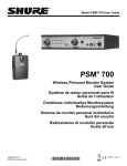
1
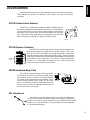
PSM 600
Personal Stereo Monitor System
PSM 600
Wireless Personal Stereo Monitor System
User Guide
Système de retour stéréo personnel sans fil
Guide de l’utilisateur
Drahtloses individuelles Stereomonitorsystem
Bedienungsanleitung
Sistema inalámbrico de monitor estereofónico personal
Guía del usuario
Sistema di controllo stereo personale senza fili
Guida d’uso
© 2008 Shure Incorporated
27C8557 (Rev. 6)
Printed in U.S.A.
! IMPORTANT SAFETY INSTRUCTIONS !
1.
2.
3.
4.
5.
6.
7.
8.
9.
10.
11.
READ these instructions.
KEEP these instructions.
HEED all warnings.
FOLLOW all instructions.
DO NOT use this apparatus near water.
CLEAN ONLY with dry cloth.
DO NOT block any ventilation openings. Install in accordance with the manufacturer's instructions.
DO NOT install near any heat sources such as radiators, heat registers, stoves,
or other apparatus (including amplifiers) that produce heat.
DO NOT defeat the safety purpose of the polarized or grounding-type plug. A
polarized plug has two blades with one wider than the other. A grounding type
plug has two blades and a third grounding prong. The wider blade or the third
prong are provided for your safety. If the provided plug does not fit into your outlet, consult an electrician for replacement of the obsolete outlet.
PROTECT the power cord from being walked on or pinched, particularly at plugs,
convenience receptacles, and the point where they exit from the apparatus.
ONLY USE attachments/accessories specified by the manufacturer.
12.
USE only with a cart, stand, tripod, bracket, or table
specified by the manufacturer, or sold with the
apparatus. When a cart is used, use caution when
moving the cart/apparatus combination to avoid
injury from tip-over.
13.
UNPLUG this apparatus during lightning storms or when unused for long periods of
time.
REFER all servicing to qualified service personnel. Servicing is required when the
apparatus has been damaged in any way, such as power-supply cord or plug is damaged, liquid has been spilled or objects have fallen into the apparatus, the apparatus
has been exposed to rain or moisture, does not operate normally, or has been
dropped.
DO NOT expose the apparatus to dripping and splashing. DO NOT put objects filled
with liquids, such as vases, on the apparatus.
The MAINS plug or an appliance coupler shall remain readily operable.
The airborne noise of the apparatus does not exceed 70dB (A).
Apparatus with CLASS I construction shall be connected to a MAINS socket outlet
with a protective earthing connection.
To reduce the risk of fire or electric shock, do not expose this apparatus to rain or
moisture.
Do not attempt to modify this product. Doing so could result in personal injury
and/or product failure.
14.
15.
16.
17.
18.
19.
20.
This symbol indicates that dangerous voltage constituting a
risk of electric shock is present within this unit.
This symbol indicates that there are important operating and
maintenance instructions in the literature accompanying this unit.
WARNING: Voltages in this equipment are hazardous to life. No user-serviceable parts inside. Refer all servicing to qualified service personnel. The
safety certifications do not apply when the operating voltage is changed from the factory setting.
! CONSIGNES DE SÉCURITÉ IMPORTANTES !
1.
2.
3.
4.
5.
6.
7.
8.
9.
10.
11.
LIRE ces consignes.
CONSERVER ces consignes.
OBSERVER tous les avertissements.
SUIVRE toutes les consignes.
NE PAS utiliser cet appareil à proximité de l'eau.
NETTOYER UNIQUEMENT avec un chiffon sec.
NE PAS obstruer les ouvertures de ventilation. Installer en respectant les consignes du fabricant.
Ne pas installer à proximité d'une source de chaleur telle qu'un radiateur, une
bouche de chaleur, un poêle ou d'autres appareils (dont les amplificateurs) produisant de la chaleur.
NE PAS détériorer la sécurité de la fiche polarisée ou de la fiche de terre. Une
fiche polarisée comporte deux lames dont l'une est plus large que l'autre. Une
fiche de terre comporte deux lames et une troisième broche de mise à la terre.
La lame la plus large ou la troisième broche assure la sécurité de l'utilisateur. Si
la fiche fournie ne s'adapte pas à la prise électrique, demander à un électricien
de remplacer la prise hors normes.
PROTÉGER le cordon d'alimentation afin que personne ne marche dessus et
que rien ne le pince, en particulier au niveau des fiches, des prises de courant
et du point de sortie de l'appareil.
UTILISER UNIQUEMENT les accessoires spécifiés par le fabricant.
12.
13.
14.
15.
16.
17.
18.
19.
20.
Ce symbole indique la présence d'une tension dangereuse dans
l'appareil constituant un risque de choc électrique.
UTILISER uniquement avec un chariot, un pied, un trépied,
un support ou une table spécifié par le fabricant ou vendu
avec l'appareil. Si un chariot est utilisé, déplacer l'ensemble
chariot-appareil avec précaution afin de ne pas le renverser,
ce qui pourrait entraîner des blessures.
DÉBRANCHER l'appareil pendant les orages ou quand il ne sera pas utilisé pendant
longtemps.
CONFIER toute réparation à du personnel qualifié. Des réparations sont nécessaires
si l'appareil est endommagé de quelque façon que ce soit, comme par exemple : cordon ou prise d'alimentation endommagé, liquide renversé ou objet tombé à l'intérieur
de l'appareil, exposition de l'appareil à la pluie ou à l'humidité, appareil qui ne marche
pas normalement ou que l'on a fait tomber.
NE PAS exposer cet appareil aux égouttures et aux éclaboussements. NE PAS poser
des objets contenant de l'eau, comme des vases, sur l'appareil.
La prise SECTEUR ou un adaptateur d'alimentation doit toujours rester prêt(e) à être
utilisé(e).
Le bruit aérien de l'appareil ne dépasse pas 70 dB (A).
L'appareil de construction de CLASSE I doit être raccordé à une prise SECTEUR
dotée d'une protection par mise à la terre.
Pour réduire les risques d'incendie ou de choc électrique, ne pas exposer cet
appareil à la pluie ou à l'humidité.
Ne pas essayer de modifier ce produit. Une telle opération est susceptible
d'entraîner des blessures ou la défaillance du produit.
Ce symbole indique que la documentation fournie avec l'appareil contient
des instructions d'utilisation et d'entretien importantes.
AVERTISSEMENT : Les tensions à l'intérieur de cet équipement peuvent être mortelles. Aucune pièce interne réparable par l'utilisateur. Confier toute réparation à du personnel qualifié. Les certifications de sécurité sont invalidées lorsque le réglage de tension d'usine est changé.
! WICHTIGE SICHERHEITSHINWEISE !
1.
2.
3.
4.
5.
6.
7.
8.
9.
10.
11.
Diese Hinweise LESEN.
Diese Hinweise AUFHEBEN.
Alle Warnhinweise BEACHTEN.
Alle Anweisungen BEFOLGEN.
Dieses Gerät NICHT in der Nähe von Wasser verwenden.
NUR mit einem sauberen Tuch REINIGEN.
KEINE Lüftungsöffnungen verdecken. Gemäß den Anweisungen des Herstellers einbauen.
Nicht in der Nähe von Wärmequellen, wie Heizkörpern, Raumheizungen,
Herden oder anderen Geräten (einschließlich Verstärkern) installieren, die
Wärme erzeugen.
Die Schutzfunktion des Schukosteckers NICHT umgehen. Bei Steckern für die
USA gibt es polarisierte Stecker, bei denen ein Leiter breiter als der andere ist;
US-Stecker mit Erdung verfügen über einen dritten Schutzleiter. Bei diesen
Steckerausführungen dient der breitere Leiter bzw. der Schutzleiter Ihrer
Sicherheit. Wenn der mitgelieferte Stecker nicht in die Steckdose passt, einen
Elektriker mit dem Austauschen der veralteten Steckdose beauftragen.
VERHINDERN, dass das Netzkabel gequetscht oder darauf getreten wird, insbesondere im Bereich der Stecker, Netzsteckdosen und an der Austrittsstelle
vom Gerät.
NUR das vom Hersteller angegebene Zubehör und entsprechende
Zusatzgeräte verwenden.
12.
NUR in Verbindung mit einem vom Hersteller angegebenen oder mit
dem Gerät verkauften Transportwagen, Stand, Stativ, Träger oder
Tisch verwenden. Wenn ein Transportwagen verwendet wird, beim
Verschieben der Transportwagen-Geräte Einheit vorsichtig vorgehen,
um Verletzungen durch Umkippen zu verhüten.
13.
Das Netzkabel dieses Geräts während Gewittern oder bei längeren Stillstandszeiten
aus der Steckdose ABZIEHEN.
Alle Reparatur- und Wartungsarbeiten von qualifiziertem Kundendienstpersonal
DURCHFÜHREN LASSEN. Kundendienst ist erforderlich, wenn das Gerät auf
irgendwelche Weise beschädigt wurde, z.B. wenn das Netzkabel oder der
Netzstecker beschädigt wurden, wenn Flüssigkeiten in das Gerät verschüttet wurden
oder Fremdkörper hineinfielen, wenn das Gerät Regen oder Feuchtigkeit ausgesetzt
war, nicht normal funktioniert oder fallen gelassen wurde.
Dieses Gerät vor Tropf- und Spritzwasser SCHÜTZEN. KEINE mit Wasser gefüllten
Gegenstände wie zum Beispiel Vasen auf das Gerät STELLEN.
Der Netzstecker oder ein Gerätekuppler müssen leicht betriebsbereit bleiben.
Der Luftschall des Geräts überschreitet 70 dB (A) nicht.
Das Gerät mit Bauweise der KLASSE I muss mit einem Schukostecker mit Schutzleiter in eine Netzsteckdose mit Schutzleiter eingesteckt werden.
Dieses Gerät darf nicht Regen oder Feuchtigkeit ausgesetzt werden, um das
Risiko von Bränden oder Stromschlägen zu verringern.
Nicht versuchen, dieses Produkt zu modifizieren. Ansonsten könnte es zu Verletzungen und/oder zum Produktausfall kommen.
14.
15.
16.
17.
18.
19.
20.
Dieses Symbol zeigt an, dass gefährliche Spannungswerte,
die ein Stromschlagrisiko darstellen, innerhalb dieses
Geräts auftreten
Dieses Symbol zeigt an, dass das diesem Gerät beiliegende
Handbuch wichtige Betriebs- und Wartungsanweisungen enthält.
ACHTUNG: Die in diesem Gerät auftretenden Spannungen sind lebensgefährlich. Das Gerät enthält keine Teile, die vom Benutzer gewartet
werden können. Alle Reparatur- und Wartungsarbeiten von qualifiziertem Kundendienstpersonal durchführen lassen. Die Sicherheitszulassungen gelten nicht mehr, wenn die Werkseinstellung der Betriebsspannung geändert wird.
! INSTRUCCIONES IMPORTANTES DE SEGURIDAD !
1.
2.
3.
4.
5.
6.
7.
8.
9.
10.
11.
LEA estas instrucciones.
CONSERVE estas instrucciones.
PRESTE ATENCION a todas las advertencias.
SIGA todas las instrucciones.
NO utilice este aparato cerca del agua.
LIMPIESE UNICAMENTE con un trapo seco.
NO obstruya ninguna de las aberturas de ventilación. Instálese según lo
indicado en las instrucciones del fabricante.
No instale el aparato cerca de fuentes de calor tales como radiadores, registros
de calefacción, estufas u otros aparatos (incluyendo amplificadores) que
produzcan calor.
NO anule la función de seguridad del enchufe polarizado o con clavija de
puesta a tierra. Un enchufe polarizado tiene dos patas, una más ancha que la
otra. Un enchufe con puesta a tierra tiene dos patas y una tercera clavija con
puesta a tierra. La pata más ancha o la tercera clavija se proporciona para su
seguridad. Si el tomacorriente no es del tipo apropiado para el enchufe, consulte a un electricista para que sustituya el tomacorriente de estilo anticuado.
PROTEJA el cable eléctrico para evitar que personas lo pisen o estrujen, particularmente en sus enchufes, en los tomacorrientes y en el punto en el cual
sale del aparato.
UTILICE únicamente los accesorios especificados por el fabricante.
12.
13.
14.
15.
16.
17.
18.
19.
20.
UTILICESE únicamente con un carro, pedestal, trípode,
escuadra o mesa del tipo especificado por el fabricante o vendido con el aparato. Si se usa un carro, el mismo debe moverse con sumo cuidado para evitar que se vuelque con el
aparato.
DESENCHUFE el aparato durante las tormentas eléctricas, o si no va a ser utilizado
por un lapso prolongado.
TODA reparación debe ser llevada a cabo por técnicos calificados. El aparato
requiere reparación si ha sufrido cualquier tipo de daño, incluyendo los daños al
cordón o enchufe eléctrico, si se derrama líquido sobre el aparato o si caen objetos
en su interior, si ha sido expuesto a la lluvia o la humedad, si no funciona de modo
normal, o si se ha caído.
NO exponga este aparato a chorros o salpicaduras de líquidos. NO coloque objetos
llenos con líquido, tales como floreros, sobre el aparato.
El enchufe de alimentación principal o acoplador de aparato electrodoméstico deberá
permanecer en condiciones de funcionamiento.
El nivel de ruido transmitido por el aire del aparato no excede de 70 dB (A).
Los aparatos de fabricación CLASE I deberán conectarse a un tomacorriente DE
ALIMENTACIÓN con clavija de puesta a tierra protectora.
Para reducir el riesgo de causar un incendio o sacudidas eléctricas, no exponga
este aparato a la lluvia ni a humedad.
No intente modificar este producto. Hacerlo podría causar lesiones personales y/
o la falla del producto.
Este símbolo indica que la literatura que acompaña a esta
unidad contiene instrucciones importantes de funcionamiento
y mantenimiento.
Este símbolo indica que la unidad contiene niveles de voltaje
peligrosos que representan un riesgo de choques eléctricos.
ADVERTENCIA: Los voltajes presentes en este equipo representan un riesgo para la vida. No contiene componentes reparables por el
usuario. Toda reparación debe ser llevada a cabo por técnicos calificados. Las certificaciones de seguridad no tienen vigencia cuando el
voltaje de funcionamiento de la unidad es cambiado a un valor distinto al ajustado en fábrica.
! ISTRUZIONI IMPORTANTI PER LA SICUREZZA !
1.
2.
3.
4.
5.
6.
7.
8.
9.
10.
11.
EGGETE queste istruzioni.
CONSERVATE queste istruzioni.
OSSERVATE tutte le avvertenze.
SEGUITE tutte le istruzioni.
NON usate questo apparecchio vicino all'acqua.
PULITE l'apparecchio SOLO con un panno asciutto.
NON ostruite alcuna apertura per l'aria di raffreddamento. Installate l'apparecchio seguendo le istruzioni del costruttore.
NON installate l'apparecchio accanto a fonti di calore quali radiatori, aperture
per l'efflusso di aria calda, forni o altri apparecchi (amplificatori inclusi) che generino calore.
NON modificate la spina polarizzata o con spinotto di protezione. Una spina polarizzata è dotata di due lame, una più ampia dell'altra. Una spina con spinotto è dotata di due lame e di un terzo polo di messa a terra. La lama più ampia ed il terzo
polo hanno lo scopo di tutelare la vostra incolumità. Se la spina in dotazione non si
adatta alla presa di corrente, rivolgetevi ad un elettricista per far eseguire le modifiche necessarie.
EVITATE di calpestare il cavo di alimentazione o di comprimerlo, specie in corrispondenza di spine, prese di corrente e punto di uscita dall'apparecchio.
USATE ESCLUSIVAMENTE i dispositivi di collegamento e gli accessori specificati
dal costruttore.
12.
13.
14.
15.
16.
17.
18.
19.
20.
Questo simbolo indica la presenza di alta tensione all'interno
dell'apparecchio, che comporta il rischio di folgorazione.
USATE l'apparecchio solo con carrelli, sostegni, treppiedi,
staffe o tavoli specificati dal costruttore o venduti insieme
all'apparecchio stesso. Se usate un carrello, fate attenzione
durante gli spostamenti per evitare infortuni causati da un
eventuale ribaltamento del carrello stesso.
SCOLLEGATE l'apparecchio dalla presa di corrente in caso di temporali o di non utilizzo per un lungo periodo.
RIVOLGETEVI a personale di assistenza qualificato per qualsiasi intervento. È necessario intervenire sull'apparecchio ogniqualvolta sia stato danneggiato, in qualsiasi
modo, ad esempio in caso di danneggiamento di spina o cavo di alimentazione, versamento di liquido sull'apparecchio o caduta di oggetti su di esso, esposizione
dell'apparecchio a pioggia o umidità, funzionamento irregolare o caduta.
NON esponetelo a sgocciolamenti o spruzzi. NON appoggiate sull'apparecchio
oggetti pieni di liquidi, ad esempio vasi da fiori.
La spina di alimentazione o un attacco per elettrodomestici devono essere sempre pronti per l'uso.
Il rumore aereo dell'apparecchio non supera i 70dB (A).
L'apparato con costruzione di CLASSE I va collegato ad una presa elettrica dotata di messa a terra di protezione.
Per ridurre il rischio di incendio o folgorazione, non esponete questo apparecchio alla pioggia o all’umidità.
Non tentate di modificare il prodotto. Tale operazione può causare infortuni e/o il
guasto del prodotto stesso.
Questo simbolo indica la presenza di istruzioni importanti per
l'uso e la manutenzione nella documentazione in dotazione
all'apparecchio.
AVVERTENZA: le tensioni all'interno di questo apparecchio possono essere letali. L'apparecchio non contiene parti che possono essere
riparate dall'utente. Per qualsiasi intervento, rivolgetevi a personale di assistenza qualificato. Le certificazioni di sicurezza non sono valide se
si cambia la tensione di funzionamento rispetto al valore prefissato in fabbrica.
WARNING!
USE OF THIS SYSTEM AT AN EXCESSIVE VOLUME MAY RESULT IN PERMANENT HEARING DAMAGE.
OPERATE AT THE LOWEST POSSIBLE VOLUME.
In order to use this system safely, avoid prolonged listening at excessive sound pressure levels. Please refer to the
following guidelines established by the Occupational Safety Health Administration (OSHA) on maximum time
exposure to sound pressure levels before hearing damage occurs.
90 dB SPL at 8 hours
95 dB SPL at 4 hours
100 dB SPL at 2 hours
105 dB SPL at 1 hour
110 dB SPL at 1/2 hour
115 dB SPL at 15 minutes
120 dB SPL — avoid or damage may occur
It is difficult to measure the exact Sound Pressure Levels (SPL) present at the eardrum in live applications. In addition
to the volume setting on the PSM, the SPL in the ear is affected by ambient sound from floor wedges or other devices.
The isolation provided by the fit of quality earpieces is also an important factor in determining the SPL in the ear.
Here are some general tips to follow in the use of this product to protect your ears from damage:
1. Turn up the volume control only far enough to hear properly.
2. Ringing in the ears may indicate excessive gain levels. Try lowering the gain levels.
3. Have your ears checked regularly by an audiologist. If you suffer wax buildup, stop using the system and consult
an audiologist.
4. Wipe the ear molds with an antiseptic before and after use to avoid infections. Stop using the ear molds if they are
causing great discomfort or infection.
FCC Statement. The P6R Receiver complies with part 15 of the FCC Fules. Operation is subject to the following
two conditions: (1) This device may not cause harmful interference and (2) this device must accept any
interference received, including inerference that may cause undesired operation.
Licensing Statement. Changes or modifications not expressly approved by Shure Brothers Inc. could void your
authority to operate the equipment. Licensing of Shure wireless microphone equipment is the user’s responsibility,
and licensability depends on the user’s classification and application. Shure strongly urges the user to contact the
appropriate authority concerning proper licensing.
Note: This equipment has been tested and found to comply with the limits for a Class B digital device, pursuant to part
15 of FCC Rules. These limits are designed to provide reasonable protection against harmful interference in a
residential installation. This equipment generates, uses and can radiate radio frequency energy and, if not installed and
used in accordance with the instructions, may cause harmful interference to radio communications. However, there
is no guarantee that interference will not occur in a particular installation. If this equipment does cause harmful
interference to radio or television reception, which can be determined by turning the equipment off and on, the user
is encouraged to try to correct the interference by one or more of the following measures:
S
Reorient or relocate the receiving antenna.
S
Increase the separation between the equipment and the receiver.
S
Connect the equipment into an outlet on a circuit different from that to which the receiver is connected.
S
Consult the dealer or an experienced radio/TV technician for help.
1
TABLE OF CONTENTS
Getting Started with the PSM600 . . . . . . . . . . . . . . . . . . . . . . . . . . . . . . . . . . . . . . . . . . . . . . . . . . . . . . . . . . . . . . . . . 3
Introduction . . . . . . . . . . . . . . . . . . . . . . . . . . . . . . . . . . . . . . . . . . . . . . . . . . . . . . . . . . . . . . . . . . . . . . . . . . . . . . . . . . . . .
Description . . . . . . . . . . . . . . . . . . . . . . . . . . . . . . . . . . . . . . . . . . . . . . . . . . . . . . . . . . . . . . . . . . . . . . . . . . . . . . . . . .
Components . . . . . . . . . . . . . . . . . . . . . . . . . . . . . . . . . . . . . . . . . . . . . . . . . . . . . . . . . . . . . . . . . . . . . . . . . . . .
Features . . . . . . . . . . . . . . . . . . . . . . . . . . . . . . . . . . . . . . . . . . . . . . . . . . . . . . . . . . . . . . . . . . . . . . . . . . . . . . .
4
4
4
4
Overview . . . . . . . . . . . . . . . . . . . . . . . . . . . . . . . . . . . . . . . . . . . . . . . . . . . . . . . . . . . . . . . . . . . . . . . . . . . . . . . . . . . . . . .
P6T Transmitter . . . . . . . . . . . . . . . . . . . . . . . . . . . . . . . . . . . . . . . . . . . . . . . . . . . . . . . . . . . . . . . . . . . . . . . . . . . . . .
Front Panel . . . . . . . . . . . . . . . . . . . . . . . . . . . . . . . . . . . . . . . . . . . . . . . . . . . . . . . . . . . . . . . . . . . . . . . . . . . . .
Back Panel . . . . . . . . . . . . . . . . . . . . . . . . . . . . . . . . . . . . . . . . . . . . . . . . . . . . . . . . . . . . . . . . . . . . . . . . . . . . .
P6R Receiver . . . . . . . . . . . . . . . . . . . . . . . . . . . . . . . . . . . . . . . . . . . . . . . . . . . . . . . . . . . . . . . . . . . . . . . . . . . . . . . .
Controls and Connectors . . . . . . . . . . . . . . . . . . . . . . . . . . . . . . . . . . . . . . . . . . . . . . . . . . . . . . . . . . . . . . . . .
DIP Switches . . . . . . . . . . . . . . . . . . . . . . . . . . . . . . . . . . . . . . . . . . . . . . . . . . . . . . . . . . . . . . . . . . . . . . . . . . .
5
5
5
5
6
6
6
Installation and Applications . . . . . . . . . . . . . . . . . . . . . . . . . . . . . . . . . . . . . . . . . . . . . . . . . . . . . . . . . . . . . . . . . . . . . 7
Operating Modes . . . . . . . . . . . . . . . . . . . . . . . . . . . . . . . . . . . . . . . . . . . . . . . . . . . . . . . . . . . . . . . . . . . . . . . . . . . . . 7
Stereo Control . . . . . . . . . . . . . . . . . . . . . . . . . . . . . . . . . . . . . . . . . . . . . . . . . . . . . . . . . . . . . . . . . . . . . . . . . . 7
MixMode Control . . . . . . . . . . . . . . . . . . . . . . . . . . . . . . . . . . . . . . . . . . . . . . . . . . . . . . . . . . . . . . . . . . . . . . . 8
Mono Control . . . . . . . . . . . . . . . . . . . . . . . . . . . . . . . . . . . . . . . . . . . . . . . . . . . . . . . . . . . . . . . . . . . . . . . . . . . 8
Loop Applications . . . . . . . . . . . . . . . . . . . . . . . . . . . . . . . . . . . . . . . . . . . . . . . . . . . . . . . . . . . . . . . . . . . . . . . . . . . . 9
Running Multiple PSM600 Wireless Systems under Stereo Control . . . . . . . . . . . . . . . . . . . . . . . . . . . . 9
Running Floor Monitors through a P6T Transmitter . . . . . . . . . . . . . . . . . . . . . . . . . . . . . . . . . . . . . . . . . . 9
Running Multiple PSM600 Systems under MixMode Control . . . . . . . . . . . . . . . . . . . . . . . . . . . . . . . . . 10
Running a Recording Device through a P6T Transmitter . . . . . . . . . . . . . . . . . . . . . . . . . . . . . . . . . . . . . 10
Accessories . . . . . . . . . . . . . . . . . . . . . . . . . . . . . . . . . . . . . . . . . . . . . . . . . . . . . . . . . . . . . . . . . . . . . . . . . . . . . . . . 11
Troubleshooting . . . . . . . . . . . . . . . . . . . . . . . . . . . . . . . . . . . . . . . . . . . . . . . . . . . . . . . . . . . . . . . . . . . . . . . . . . . . . . . . 12
Appendix A. Specifications . . . . . . . . . . . . . . . . . . . . . . . . . . . . . . . . . . . . . . . . . . . . . . . . . . . . . . . . . . . . . . . . . . . . . 12
Custom Earpieces . . . . . . . . . . . . . . . . . . . . . . . . . . . . . . . . . . . . . . . . . . . . . . . . . . . . . . . . . . . . . . . . . . . . . . . . . . . 14
Voltage Selection . . . . . . . . . . . . . . . . . . . . . . . . . . . . . . . . . . . . . . . . . . . . . . . . . . . . . . . . . . . . . . . . . . . . . . . . . . . . 14
Appendix B. Rack Mounting Options . . . . . . . . . . . . . . . . . . . . . . . . . . . . . . . . . . . . . . . . . . . . . . . . . . . . . . . . . . . . 15
Rack Mounting the P6T Transmitter . . . . . . . . . . . . . . . . . . . . . . . . . . . . . . . . . . . . . . . . . . . . . . . . . . . . . . . . . . . . 15
Front Mounting the Antenna . . . . . . . . . . . . . . . . . . . . . . . . . . . . . . . . . . . . . . . . . . . . . . . . . . . . . . . . . . . . . . . . . . 16
2
GETTING STARTED WITH THE PSM600 SYSTEM
Thank you for purchasing the PSM600 Personal Stereo Monitor System. The
PSM600 is a revolutionary new product family designed to meet the diverse audio
monitoring needs of musicians, engineers, and stage performers.
This section outlines step-by-step instructions to quickly show you how to connect
your PSM system to an audio source while introducing you to some of its features.
P6T Transmitter Setup
3. 2.
1.
4.
1. Plug the power cord to the power connector.
Connect the other end to a power supply.
2. Attach the antenna to the
ANTENNA OUT BNC connector.
3. Plug the cable(s) from the audio source (mixer,
audio output, CD player) into the LEFT/RIGHT
audio inputs. For a stereo send, use both inputs.
For mono send, use either the LEFT or RIGHT input.
NOTE: All inputs are phantom power
protected up to 60 VDC.
4. Put the PAD switch in the +4 dB if the input
signal is +4 dB, or the –10 dB position, if the
input signal is –10 dB.
5. Turn on the P6T Transmitter.
6. Set the SOURCE switch to match the
audio send (stereo/mono).
8.
6.
7. 5.
7. Set the FREQuency switch in the UP position
to frequency #1.
IMPORTANT: Never set more than ONE transmitter to the same
operating frequency.
8. Power on the audio source and adjust the level control so the LEDs are in the –3
dB to +3 dB range.
P6R Receiver Setup
9. Attach the bodypack antenna (PA710) to the
15.
ANTENNA connector by aligning the red dot and
threading the shell until it is tight.
10. Open the battery door and insert a 9V alkaline battery.
13.
9.
12.
11. Set the DIP switches according to the illustration.
#1: UP – Frequency #1
#2: DOWN – Stereo control
#3: UP – High frequency boost
#4: UP – Limiter on
12. Set the balance control to the center detent position.
10. & 11.
13. Insert the plug of the earpieces into the headphone
connector on the top panel.
14. Insert the earpieces into your ears.
15. Turn on the receiver by rotating the volume knob clockwise past the click, then
slowly raise the volume to a comfortable listening level.
Now you know the basic setup for your new PSM600 Personal Stereo Monitor
System. If any troubles occur, please refer to the Troubleshooting section of this manual.
The rest of the manual goes into greater detail on features and applications — including
MixModet control, which enables you to customize your own mixes. Please read the rest
of the manual to help you make the most of your PSM600 System.
3
INTRODUCTION
Description
The Shure PSM600 Personal Stereo Monitor System is a UHF wireless, two-channel
stereo, monitor system designed for onstage applications. The PSM has several
advantages over onstage loudspeaker monitors: it is less visible, has better sound, allows
freedom of movement, and reduces the chances of feedback. It is a versatile system,
designed for use in many different sound reinforcement applications: public address, live
music, theater, and electronic news gathering (ENG). The wireless system is frequency
compatible with other Shure UHF and VHF wireless systems.
Components
P6T WIRELESS TRANSMITTER
SCL3 EARPHONES
PA715 ANTENNA
P6R WIRELESS RECEIVER
P6T Wireless Transmitter with rack-mounting hardware and one antenna
P6R Wireless Body-Pack Receiver with antenna
SCL3 Earphones with soft gray flex sleeves
Features
4
S
UHF operation.
S
S
Stereo or MixModet control for custom monitor
mixes.
Volume and Balance dials on the P6R Receiver
for easy user access.
S
Internal linear power supply on P6T, switchable
between 120 VAC and 230 VAC.
S
Peak transmitter modulation limiter with fixed
threshold and modulation limit indicators.
S
Loop out connectors on P6T for multiple mix
setups and easy installation.
S
Tone-Key squelch.
S
Half-rack chassis on P6T complete with
mounting hardware.
S
2 user-selectable frequencies per system.
S
Up to10 compatible frequencies for 10 separate
mixes.
S
Frequency compatible with all Shure Wireless
systems (country dependent).
S
MPX Stereo audio transmission.
S
Switchable high-frequency boost on P6R.
S
+4 dBu/–10 dBV input level select switch on P6T.
S
All metal construction on P6T and P6R
S
Electronically balanced, combined 1/4-in./XLR
connectors on P6T can be used with balanced or
unbalanced connections.
S
Headphone monitor on P6T for local listening.
OVERVIEW
P6T Transmitter
Front Panel
Ê
Ê
Ë
Ì
Í
Ë
Ì
Í
Î
INPUT Dial. This controls the signal level to the
transmitter modulator. For optimum sound, the
input level should be set in the –3 dB to +3 dB
range.
Stereo INPUT Meters. Each channel has an eight
LED meter which indicates the modulation level of
the radio signal. Important: When the LIM (limit)
LEDs illuminate, the system is overdriven. Reduce
the input knob to keep the input level LEDs at
around –3 dB to +3 dB.
Ï
SOURCE Switch. Set to MONO when only one
input is needed. Set to STEREO/MixMode when
both inputs are needed.
Ð
Î
Ï
Ð
Headphone Connectors — 1/4-in. phone and 3.5
mm (1/8-in) mini. Each connector is configured as
left=tip, right=ring, ground=sleeve. Please note
that only one of these outputs can be used at a
time.
Frequency Switch and Indicators. This switch
determines the frequency the P6T transmits. The
frequencies your particular unit operates at are
indicated just above this switch. The LEDs indicate
which frequency the unit is transmitting: RED =
frequency 1, GREEN = frequency 2. These LEDs
also act as power-on indicators.
Power Switch. Press this button to turn the unit on.
PHONES Volume Dial. This dial controls the
signal level to the headphone output, without
affecting the input level.
Rear Panel
Ê
Ê
Ë
Ì
Ë
Power Connector with Integral Fuse. Connects
to a power supply. The fuse is located in the bottom
drawer.
LOOP OUT Connectors — 1/4-in. phone,
balanced. Additional connectors internally wired
to the respective LEFT/RIGHT input connectors.
INPUT PAD Switch. Selects the input level for –10
dBV or +4 dBu operation.
Ì
Í
Í
Î
Î
LEFT/CH. 1 and RIGHT/CH. 2 Input Connectors
— Combined 1/4-in. phone and XLR (female),
balanced. Electronically balanced inputs can be
used with either balanced or unbalanced outputs.
Either connector can be used for mono control.
Antenna Connector — 50 Ω, BNC type. This
connects to the antenna to transmit UHF signals to
the receiver.
5
P6R Receiver
Controls and Connectors
Ì
Ê
Ï
ÊË Í Î Ð
Ê
Ë
Ì
Í
Î
Ï Î
Ó
Ò
Ñ
Ó
Balance Dial. In stereo mixes, this controls the
left/right balance. In MixModet, this controls the
mix level of two transmitter inputs.
Ï
Headphone Connector. 3.5 mm (1/8-in.) jack
connects to the earphones. Left=tip, right=ring,
ground=sleeve.
Ð
LOW BATT Indicator. This red LED illuminates
when the battery has approximately 45 minutes of
operating time remaining, depending on the
volume.
Power LED. This green LED illuminates when the
power is ON and the battery is good.
ON/OFF and Volume Dial. Full counter-clockwise
turns the P6R OFF. Turn the dial clockwise past the
click to turn the P6R ON. Once ON, turn the dial
clockwise
to
raise
the
volume,
and
Ñ
Ò
Ó
counter-clockwise to lower the volume in the
earpieces.
Antenna and Connector. An easily removable
antenna connects to the P6R to receive RF signals
from the P6T Transmitter.
RF LED. Illuminates when the P6R is receiving a
signal from the transmitter.
Battery Compartment. Accepts one 9-volt battery
(Duracell recommended). Open the door by
pressing the latches on both sides and pulling.
DIP Switches. Using the DIP Switches, you can
customize the operation of the receiver. See DIP
Switches (below).
Belt Clip. Secures the P6R to a belt, pocket, or to
other clothing.
DIP Switches
DIP
SWITCH
6
FUNCTION
1
Frequency Select
2
Stereo/MixMode Select
3
Equalization (Flat/High Boost)
4
Limiter defeat
UP
DOWN
Frequency 1
Frequency 2
MixMode control
stereo control
Gives a 6 dB boost at 10 kHz
for a better high-end response
normal response
Limiter on
Limiter off
IMPORTANT: The Limiter is designed to respond to and limit the loudness of
unexpectedly high signals. It is not designed to prevent long term exposure to high SPL
levels. It is designed for use with Shure earphones, so the maximum limited SPL
may be different with other earpieces. We recommend that you always use the built-in
limiter provided with this system. However, a limiter defeat switch has been provided for
those who would prefer to use an external limiter product.
INSTALLATION AND APPLICATIONS
The flexible design of the PSM600 Personal Stereo Monitor System makes
configuring a monitor mix very simple. In addition, the unique MixMode circuitry enables
you to customize your own individual mix in a multiple mix environment. To help you install
the PSM600 into your sound system, the tables and diagrams in this section describe
three distinct modes of operating or controlling the system. Although the examples show
only single system setups, you can configure multiple wireless systems in a setup. Some
multiple mix setups are detailed in the LOOP Applications section of this chapter.
Operating Modes
Stereo Control
MixMode Control
Mono Control
Used for conventional Stereo monitor mixes.
Transmitter Stereo/MixMode setting
Receiver Stereo setting
Balance Dial Varies stereo left/right image
Used for creating an individual mix between two distinct monitor sends.
Transmitter Stereo/MixMode setting
Receiver MixMode setting
Balance Dial Varies levels between mixes
Used when only one (mono) monitor mix is available.
Transmitter Mono setting
Receiver Stereo setting
Balance Dial Varies the right/left volume control
NOTE: For consistency throughout the following diagrams, a mixing console is shown as
the source supplying the audio signal to the P6T Transmitter. However, any balanced or
unbalanced send that outputs a line level should drive the P6T Transmitter adequately.
Some devices that would work are a CD player, DAT machine, direct out box, signal
processing equipment, and microphone preamps.
Stereo Control
This diagram shows how to connect the PSM600 system with a stereo monitor mix.
ÑÑÑÑ
ÑÑ
ÑÑÑÑ
ÑÑ
Ñ
P6T
P6R
MIXER
1. Connect the stereo mixer outputs to the L/CH1. and R/CH2. INPUTs on the P6T
Transmitter
2. Set the SOURCE switch on the P6T front panel to STEREO.
3. Set DIP switch 2 of the P6R Receiver to STEREO.
4. Set DIP switch 1 on the P6R and the FREQ. switch on the P6T to the same frequency.
5. Use the balance dial on the P6R Receiver to adjust the balance of the Right and
Left channel volume.
7
MixMode Control
This diagram shows how to connect the PSM600 system with two monitor mixes
combined at the receiver. This allows you to vary the level between the two mixes to
create a custom mix.
Ñ
Ñ
Ñ Ñ
VOICE MIX
FULL LEFT
BAND MIX LOUDER
BAND MIX
FULL RIGHT
VOICE MIX LOUDER
P6T
P6R
CH. 1
CH. 2
CH. 1
MIXER
1. Connect the monitor mix 1 and monitor mix 2 mixer outputs of the mixer to the
L/CH. 1 and R/CH. 2 audio inputs of the P6T Transmitter.
2. Set the SOURCE switch on the P6T Transmitter to STEREO.
3. Set DIP switch 2 on the P6R Receiver to MixModet.
4. Set DIP switch 1 on the P6R and the FREQ. switch on the P6T to the same frequency.
5. Use the balance dial on the P6R to adjust the relative levels between the two
monitor mixes.
Mono Control
This diagram shows how to connect the PSM600 system with a mono monitor mix.
Ñ
P6T
P6R
MIXER
1. Connect the mono monitor output of the mixer to either the Left or Right audio
inputs of the P6T.
2. Flip the SOURCE switch on the front panel to MONO.
3. Flip DIP switch 2 of the P6R to STEREO.
4. Set DIP switch 1 on the P6R and the FREQ. switch on the P6T to the same frequency.
8
CH. 2
LOOP Applications
The LOOP OUT L (left) and R (right) outputs allow the signal going through the P6T to
be run to other devices. The LOOP feature of the P6T can be used for any number of
applications. Shown here are only a few examples of how it can be used.
NOTE: The LOOP connectors act as either inputs or outputs. They can
be used as outputs when the LEFT and RIGHT INPUT connectors are
used for input. However, LOOP connectors can also act as inputs when
connected directly to the outputs of a mixer. When the LOOP connectors
are used as inputs, the LEFT and RIGHT INPUT connectors act as
outputs. These diagrams show the LOOP connectors being used as
outputs. Also, the input pad does not affect the level of the LOOP signals.
Running Multiple PSM Wireless Systems Under Stereo Control
The LOOP INPUT connectors can be used to send the same monitor stereo signals to
multiple P6T wireless transmitters. This will free up busses on the mixing console,
allowing you more freedom with your audio system. Simply connect a P6T to the mixing
console as described in Stereo Control, then run 1/4-in to 1/4-in from the L/R LOOP
connectors of the first unit to the LEFT/RIGHT Input connectors of the next unit. Connect
subsequent unit in the same way.
Ñ
ÑÑ
Ñ
ÑÑ
ÑÑ
Ñ
P6T #1
P6T #2
P6R #1
MIXER
P6T #3
P6R #2
P6R #3
Running Floor Monitors Through a P6T Transmitter
The monitor audio signal can be sent through the LOOP connectors to another
amplifier, such as an amplifier for an onstage monitor system. When setup this way, the
P6R and the onstage monitors will have the same audio.
ÑÑÑ
ÑÑ
P6T
P6R
ÑÑ
FLOOR MONITOR
AMPLIFIER
MIXER
9
Running Multiple PSM Wireless Systems Under MixMode Control
A main mono monitor mix can be sent to multiple P6T transmitters, then independent
monitor mixes can be sent to the second channel of each. This will allow an entire band to
hear the same monitor mix, while giving each individual player a separate mix of their own.
Each player can then use the balance knob to adjust the levels between their own mix and
the main mono monitor mix.
ÑÑÑ Ñ
ÑÑ
P6T #1
P6T #2
P6R #1
P6T #3
MIXER
P6R #2
P6R #3
Running a Recording Device Through a P6T Transmitter
If you would like to make a recording of a performance, the LOOP outputs can be
connected to the inputs of a tape deck, DAT, or other recording device.
Ñ
Ñ Ñ
Ñ
AUX 1
OUT
P6T
AUX 2
OUT
P6R
Ñ
CASSETTE RECORDER
MIXER
10
ACCESSORIES
Several additional products have been developed as part of the PSM product family.
These products can enhance the operation of your system, and must be purchased
separately.
PA705 Unidirectional Antenna
The PA705 is a unidirectional, remote-mountable, wideband transmitting antenna designed to provide wireless coverage in a cardioid pattern.
You can use the PA705 to secure a line-of-sight transmission path from the
transmitter to the receiver when the actual transmitters are obscured.
Also, since the PA705 has some gain (due to its directivity), it is also useful
when covering very long distances with your wireless system.
PA705
PA760 Antenna Combiner
PA760
MULTIPLE
P6Ts
The PA760 is a breakthrough new product specifically designed to improve the performance of multiple wireless monitor systems. First, it combines up to four P6T Transmitters into a single antenna with no signal loss,
thus reducing stage clutter without losing wireless range. The PA760 significantly reduces interference by lowering the Intermodulation Distortion (IMD)
levels between the four transmitters. The PA760 is an internally-powered,
half-rack unit — transportation and setup are easy. Please note that the
PA760 cannot be cascaded to other PA760’s.
P6HW Hardwired Body Pack
The P6HW is a hardwired version of the Personal Stereo Monitor for users who do not need the mobility of wireless systems, such as drummers or keyboard players.
The P6HW has the same features as the wireless version
(Stereo control, MixMode control, limiter, etc.) at a lower
price. The P6HW also includes an input pad for increased
dynamic range, as well as an input peak indicator to alert
the user when levels are too high.
Ñ
Ñ
P6HW
MIXER
SCL Earphones
SCL3
Shure offers a variety of earphones to fit your needs. Designed exclusively for PSM systems, they deliver superior sound quality. For the added
comfort of a precise fit, custom earmolds are also available for SCL3 model
earphones. For more information, see Custom Earpieces under Appendix
A. Technical Specifications.
11
TROUBLESHOOTING
PROBLEM
SOLUTION
No sound at the Receiver
n Check the power cord on the Transmitter and make sure it is
powered on.
n Make sure both the transmitter and the receiver are set to the
same frequency.
n Make sure the earpiece is plugged into the receiver.
n Make sure receiver is on and the battery is good.
n Make sure both antennas are correctly attached.
n Listen to the headphone monitor on the transmitter to check
audio feed.
Low Receiver Range
n Make sure all antennas are fully inserted and secured onto
jacks.
n Try to maintain line-of-sight between transmitter and receiver.
n Try the other frequency in case interference is limiting the
range.
n Check for television channel interference.
n Make sure the PA715 antenna is not remote mounted.
Receiver sounds fuzzy or
distorted
n Make sure no other transmitters are operating on your
frequency.
n Make sure transmitter input level is 0 dB ±3 dB for optimum
performance.
n Listen to the headphone monitor on the transmitter to check
audio feed.
n Try and maintain a minimum of 10 ft. between transmitter antennas and receiver when using multiple transmitters.
Low audio output at the
receiver headphones
n Make sure transmitter input level is 0 dB ±3 dB for optimum
performance.
n Switch the transmitter pad to –10 dBV position if the input is
too low.
APPENDIX A. TECHNICAL SPECIFICATIONS
SYSTEM
RF Carrier Frequency Range
626 to 862 MHz (country dependent)
Audio Frequency Response
50 to 15k Hz (+0, –3 dB re 1KHz); earpiece dependent
Operating Range
300 ft. (environment dependent)
Modulation
FM ±35 kHz Deviation (Nominal), MPX Stereo
Channel Separation
35 dB typical
Total Harmonic Distortion
0.8% typical (Ref. ±35 KHz deviation)
Signal-to-Noise Ratio
80 dB typical (A-weighted)
Operating Temperature
–7° C to +49° C (20° F to 120° F)
12
Polarity
P6T audio inputs to P6R audio outputs: Non-inverting
XLR: pin 2 positive with respect to pin 3
1/4-in. TRS: Tip positive with respect to ring
Certification
P6T: Certified to FCC Part 74 (FCC ID No. DD4P6T).
Certified in Canada by IC under RSS–123. UL and cUL
Listed to UL 813 and CSA C22.2 No. 1.
EP6T: Meets essential requirements of European
R&TTE Directive 99/5/EC, eligible to carry the CE mark:
O682 . Type approved to EN 300 422 Parts 1 and 2.
Meets requirements of EMC Standard EN 301 489 Parts 1
and 9. VDE GS Certified to EN 60065.
P6R: Approved under the Notification provision of FCC Part
15. Certified by IC in Canada under RSS–123. Meets the
essential requirements of European R&TTE Directive
mark. Meets
99/5/EC, eligible to carry the
requirements of EMC standard EN 301 489 Parts 1 and 9.
IMPORTANT!:
THIS RADIO EQUIPMENT IS INTENDED FOR USE IN
MUSICAL PROFESSIONAL ENTERTAINMENT AND
SIMILAR APPLICATIONS.
NOTE: THIS RADIO APPARATUS MAY BE CAPABLE
OF OPERATING ON SOME FREQUENCIES NOT
AUTHORIZED IN YOUR REGION. PLEASE
CONTACT YOUR NATIONAL AUTHORITY TO
OBTAIN
INFORMATION
ON
AUTHORIZED
FREQUENCIES FOR WIRELESS MICROPHONE
PRODUCTS IN YOUR REGION
Licensing: A ministerial license to operate this
equipment may be required in certain areas. Consult
your national authority for possible requirements.
P6T TRANSMITTER
Shure Transmitter Model P6T may be used in the
countries and frequency ranges listed in Table 1 on
page i.
RF Output Power
100 mW (+20 dBm) typical conducted (country
dependent)
Modulation Limiter
Internal peak limiter (>10:1 compression)
Antenna
External whip, 50 Ω BNC connector
Power Requirements
P6T: 100 to 120 Vac, 50/60 Hz
EP6T: 220 to 240 Vac, 50/60 Hz
NOTE: This product is not disconnected from the mains
power supply when the power switch is in the OFF
position.
Current
115 mAac maximum at 120 Vac
55 mAac maximum at 230 Vac
Fuse
P6T: 120 Vac, 160 mA/250 V time delay
EP6T: 230 Vac, 80 mA/250 V time delay
FUSE
Dimensions
44.5 mm X 197.4 mm X 238.1 mm (1 3/4 in. X 7 3/4 in. X 9
3/ in.)
8
Net Weight
1.62 kg (3 lbs., 9 oz.)
P6R RECEIVER
RF Sensitivity
1.2 µV typical
Image Rejection
70 dB typical
Spurious Rejection
60 dB typical
Squelch Threshold
4 µV typical
Antenna Input Impedance
50 Ω typical
Antenna
External, threaded connector
Power Requirements
9 V battery
Battery Life
4–6 hours, volume dependent
Audio Output Connector
3.5 mm Stereo (Left = tip, Right = ring, Ground = sleeve)
Minimum Load Impedance
16 Ω
Net Weight
0.52 lbs.
Overall Dimensions
27.18 mm X 64.52 mm X 85.09 mm
(1.070 in. X 2.540 in. X 3.350 in.)
CONNECTORS
P6T Audio Inputs (LEFT/CH.1 and RIGHT/CH.2)
Connector:
(XLR and
1/4-inch
combined)
XLR (female)
1/ -inch
4
phone jack
(female)
Configuration:
electronically
balanced
electronically
balanced
Actual
Impedance:
20 kΩ
20 kΩ
Nominal
Input Level:
+4 dBu
(+4 input level)
+4 dBu
(+4 input level)
–10 dBV
(–10 input level)
–10 dBV
(–10 input level)
+25 dBu
(+4 input level)
+25 dBu
(+4 input level)
+13 dBu
(–10 input level)
+13 dBu
(–10 input level)
Pin
Assignments:
Pin 1 = ground
Pin 2 = hot
Pin 3 = cold
Tip = hot
ring = cold
sleeve = ground
Phantom Power
Protection?
Yes
Up to 60 VDC
Yes
Up to 60 VDC
Maximum
Input Level:
P6T L/R LOOP Outputs (IN and OUT)
Connector:
(XLR and 1/4-inch combined)
1/ -inch
4
jack (female)
Configuration:
electronically
balanced
Actual
Impedance:
20 kΩ
Nominal
Input Level:
+4 dBu
(+4 input level)
–10 dBV
(–10 input level)
Maximum
Input Level:
+25 dBu
(+4 input level)
+13 dBu
(–10 input level)
13
Pin
Assignments:
Tip = hot
ring = cold
sleeve = ground
Phantom Power
Protection?
Yes
Up to 60 VDC
FURNISHED ACCESSORIES
Body-Pack Antenna . . . . . . . . . . . . . . . . . . . . . . . . . PA710
Transmitter Antenna . . . . . . . . . . . . . . . . . . . . . . . . . PA715
Rack Mount Kit . . . . . . . . . . . . . . . . . . . . . . . . . . . . . PA745
60 cm (2 ft) Coaxial Cable (RG-58/U) . . . . . . . . . . UA802
SCL3 sleeve assortment with cleaning tool
. 90XJ1371
OPTIONAL ACCESSORIES
Antenna Combiner . . . . . . . . . . . . . . . . PA760 (120 VAC)
PA760E (240 VAC)
Unidirectional Antenna . . . . . . . . . . . . . . . . . . . . . . . PA705
10 ft Coaxial Antenna Cable (BNC connector) . . . PA725
Bag of 20 Foam Ear Inserts . . . . . . . . . . . . . . . . . . . PA750
Triple-Flange Ear Inserts (2) . . . . . . . . . . . . . . . . . . PA755
CUSTOM EARPIECES
For information regarding a complete line of custom
made musicians’ earpieces, contact:
Ultimate Ears Inc.
2657 Windmill Pkwy. #391
Henderson, NV 89014
(702) 263–7805
(702) 896–8856 (fax)
www.ultimateears.com
Firehouse Productions, Inc.
12 Boice Road
Hyde Park, NY 12538
(914) 229–2055
(914) 229–0844 (fax)
Sensaphonics
660 N. Milwaukee
Chicago, IL 60622
(312) 660–1714
(312) 432–1783 (fax)
Voltage Selection
The P6T Transmitter can be internally modified to
operate from 230 Vac, 50/60 Hz power.
WARNING
Voltages in this equipment are hazardous to
life. No user-serviceable parts inside. Refer all
servicing to qualified service personnel.
The safety certifications of the P6T do not
apply when the operating voltage is changed
from the factory setting.
To change the operating voltage, follow these steps.
1. Disconnect the P6T from the ac power source.
2. Remove the eight Phillips head screws securing the top
cover.
3. Locate Voltage Selector switch SW4 adjacent to power
transformer T1 and, using a screwdriver, turn the center
rotor to the 230 V position.
4. Locate fuse and remove it. Replace it with a 80 mA, 250 V,
time delay fuse for 230-volt operation (160 mA, 250 V,
time delay fuse for 115-volt operation).
Fuse part numbers are:
Fuse Type
Shure Part No.
Part No.
80 mA, 250 V
time delay
80H380
Schurter
.034.3106
160 mA, 250 V
time delay
80K258
Littelfuse
218.160
5. Replace the power cord with a cord rated for for 230 V
operation, i.e., an IEC appliance connector on the
equipment end and a CEE 7/7 (“Schuko”) mains
connector on the other.* (Shure part #95A8247.)
14
Similarly, the EP6T can be internally modified
operate from 115 Vac, 50/60 Hz power.
to
To change the operating voltage, follow these steps.
1. Disconnect the EP6T from the ac power source.
2. Remove the eight Phillips head screws securing the top
cover.
3. Locate Voltage Selector switch SW4 adjacent to power
transformer T1 and, using a screwdriver, turn the center
rotor to the 115 V position.
4. Locate fuse and remove it. Replace it with a 160 mA, 250
V, time delay fuse for 115-volt operation (80 mA, 250 V,
time delay fuse for 230-volt operation).
Fuse part numbers are:
Fuse Type
Shure Part No.
Part No.
160 mA, 250 V
time delay
80K258
Littelfuse
218.160
80 mA, 250 V
80H380
Schurter
.034.3106
time delay
5. Replace the power cord with a cord rated for for 115 V
operation, i.e., an IEC appliance connector on the
equipment end and a mains connector suitable for 115 V
operation on the other.* (Shure part #95A8389.)
*For systems requiring other mains connectors, obtain a power cord with
an IEC 320 type mating connector for connection to the P6T, and an
appropriate plug on the other end for connection to the mains. The supplied
cord uses Harmonized IEC Cordage with color coding as follows: Brown =
Line, Blue = Neutral, Green/Yellow = Ground.
APPENDIX B. RACK MOUNTING OPTIONS
Rack Mounting the P6T Transmitter
NOTE: Dual mounting with other Shure products. The P6T can also
be dual mounted with a Shure SC or LX half-rack wireless receiver.
These same instructions apply, but the front panels will not align evenly.
The SC and LX receivers must use the SC and LX rack ears. They
cannot be mounted with P6T rack ears. However, the link bars are
universal and can be used to connect the P6T with an LX or SC receiver.
WARNING: Do not torque the screws too tightly, or the chassis may be damaged.
Single Unit
1. Remove the screws and washers from each side of the unit.
2. Align the supplied rackmount brackets over the holes.
3. Using the screws and washers from step 1, fasten the rack-mount brackets.
Dual-Mounted Units
1. Remove the screws and washers on each side of both units.
2. Placing the two units side-by-side, screw the link bars to the inside panels of each
unit. The units are designed so that the link bar on the right unit will fit directly on
top of the link bar of the left unit (facing front). Use two of the screws and
washers from step 1 per link bar to fasten the link bars.
3. Align the rackmount brackets on the outside panels of the units and fasten using
four of the screws and washers from step 1.
NOTE: The link bars are designed with recesses in the side holes where
the screw head and washer fit in. Once the link bars are screwed on
properly, the vertical holes will align. Each link bar has two threaded holes
and two unthreaded holes. In order to ensure proper fit, stack the link bars
so that the unthreaded holes on one bar align with the threaded holes on
the other bar. Then, each pair of screws fits in the opposite direction of the
other pair, ensuring the stability of the link.
4. Place the two units next to each other so the link bars overlap and the screw holes
on the two align.
5. Fasten the link bars together using 4 supplied screws and washers.
15
Mounting in an Equipment Rack
SINGLE MOUNT
DUAL MOUNT
1. Insert the unit(s) into a 19-inch equipment rack.
2. Fasten the unit(s) to the rack using all four of the supplied screws.
Front Mounting the Antenna
When rack mounting units, use the supplied cable and bulkhead adapter to front
mount the antenna. This prevents other cables from becoming entangled in the antenna
and can greatly reduce RF interference.
NOTE: The PA715 antenna, which comes supplied with the P6T; cannot
be remote mounted. Use a PA705 antenna for remote mounting.
16
TABLE 1
TABLEAU 1
TABELLE 1
TABLA 1
TABELLA 1
Country Code
Code de Pays
Lander–Kurzel
Código de país
Codice del Paese
FREQ CODE
FREQ1 (MHZ)
FREQ2 (MHZ)
USA
HA
626.475 (TV 40)
632.550 (TV 41)
A, B, CH, D, E, F,
GR, I, L, NL, P
S
DK, FIN, N
GB, IRL
HB
629.975 (TV 40)
634.775 (TV 41)
HC
642.275 (TV 42)
646.500 (TV 43)
HD
647.525 (TV 43)
653.375 (TV 44)
HE
655.250 (TV 44)
656.500 (TV 45)
MF*
801,100
802,550
MG*
805,050
810,550
MH*
808,600
813,300
MJ*
811,600
813,800
MK*
823,475
827,700
MF*
801,100
802,550
MG*
805,050
810,550
MH*
808,600
813,300
MJ*
811,600
813,800
MH*
808,600
813,300
MJ*
811,600
813,800
ML*
801,100
801,900
MM*
817,100
819,700
KB*
854,900
856,175
KC*
856,950
860,400
GROUP 1
GROUP 2
All Other Countries
Tous les autres pays
Alle anderen Länder
Demás países
Tutti gli altri Paesi
KB*
854,900
856,175
KD*
859,375
860,900
*
*
*
*Please contact your national authority for information on available legal frequencies for your area and legal use of the equipment
*Se mettre en rapport avec les autorités compétentes pour obtenir les informations sur les fréquences autorisées disponibles localement et sur l’utilisation autorisée du
matériel.
*Für Informationen bezüglich der für Ihr Gebiet verfügbaren gesetzlich zugelassenen Frequenzen und der gesetzlichen Bestimmungen für den Einsatz der Geräte setzen Sie sich bitte mit der zuständigen örtlichen Behörde in Verbindung.
* Comuníquese con la autoridad nacional para obtener información en cuanto a las frecuencias legales disponibles y usos legales del equipo en su área.
*Rivolgersi alle autorità competenti per ottenere informazioni relative alle frequenze autorizzate nella propria regione e alle norme che regolano l’uso di questo
apparecchio.
i
EU DECLARATION OF CONFORMITY
We,
of
Shure Incorporated
5800 Touhy Avenue
Niles, Illinois, 60714-4608 U.S.A.
Phone: (847) 600-2000
Web: www.Shure.com
Declare under our sole responsibility that the following product
Model: P6R
Description: Personal Stereo UHF Receiver
conforms to the essential requirements and other relevant previsions of the R&TTE Directive
(1999/5/EC).
The product complies with the following product family, harmonized or national standards:
EN 301 489-1 V1.4.1 (2002-08)
EN 301 489-9 V1.2.1 (2002-08)
EN 300 422-1 V1.2.2 (2000-08)
EN 300 422-2 V1.1.1 (2000-08)
The technical documentation is kept at:
Shure Incorporated, Corporate Quality Engineering Division
SHURE Europe GmbH, EMEA Approval
Manufacturer: Shure Incorporated
Signed: __________________________________ Date: 3 March 2006
Name and Title: Craig Kozokar, EMC Project Engineer, Corporate Quality Engineering Division
European Representative: SHURE Europe GmbH
Signed: __________________________________ Date: 3 March 2006
Name and Title: Wolfgang Bilz, Dipl. Ing. (FH), EMEA Approval
SHURE Europe GmbH
Headquarters Europe, Middle East & Africa
Wannenäcker Str. 28
D-74078 Heilbronn, Germany
Phone: +49 - (0)7131 - 7214 - 0
Fax: +49 - (0)7131 - 7214 - 14
EU DECLARATION OF CONFORMITY
We,
of
Shure Incorporated
5800 Touhy Avenue
Niles, Illinois, 60714-4608 U.S.A.
Phone: (847) 600-2000
Web: www.Shure.com
Declare under our sole responsibility that the following product
Model: P6T
Description: Personal Stereo UHF Transmitter
conforms to the essential requirements and other relevant previsions of the R&TTE Directive
(1999/5/EC).
The product complies with the following product family, harmonized or national standards:
EN 301 489-1 V1.4.1 (2002-08)
EN 301 489-9 V1.2.1 (2002-08)
EN 300 422-1 V1.2.2 (2000-08)
EN 300 422-2 V1.1.1 (2000-08)
IEC 60065:1998
EN61000-3-2:2000 Amendment A1:1998; A2:1998; A14:2000
EN 61000-3-3 Amendment A1:2001
The technical documentation is kept at:
Shure Incorporated, Corporate Quality Engineering Division
SHURE Europe GmbH, EMEA Approval
Manufacturer: Shure Incorporated
Signed: __________________________________ Date: 25 September 2007
Name and Title: Craig Kozokar, EMC Project Engineer, Corporate Quality Engineering Division
European Representative: SHURE Europe GmbH
Signed: __________________________________ Date: 25 September 2007
Name and Title: Wolfgang Bilz, Dipl. Ing. (FH), EMEA Approval
SHURE Europe GmbH
Headquarters Europe, Middle East & Africa
Wannenäcker Str. 28
D-74078 Heilbronn, Germany
Phone: +49 - (0)7131 - 7214 - 0
Fax: +49 - (0)7131 - 7214 - 14
SHURE Incorporated http://www.shure.com
United States, Canada, Latin America, Caribbean:
5800 W. Touhy Avenue, Niles, IL 60714-4608, U.S.A.
Phone: 847-600-2000 U.S. Fax: 847-600-1212 Intl Fax: 847-600-6446
Europe, Middle East, Africa:
Shure Europe GmbH, Phone: 49-7131-72140 Fax: 49-7131-721414
Asia, Pacific:
Shure Asia Limited, Phone: 852-2893-4290 Fax: 852-2893-4055
iii