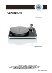
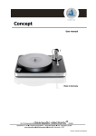
1
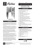
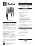
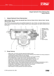
MUSICAL SURROUNDINGS PRESENTS:
THE SUPERNOVA
PHONOGRAPH PREAMPLIFIER
graph
SuperNova Phono
Preamplifier
Musical Surroundings
1
-7.5 -5
-3
2
3
-2.3
-1.7
-1
-.5
0dB
left
right
Attenuator
Status
Source Sel
ector
OWNER’S MANUAL
THE SUPERNOVA
PHONOGRAPH PREAMPLIFIER
TABLE OF CONTENTS
1)
2)
3)
4)
5)
6)
7)
8)
INTRODUCING: THE SUPERNOVA
SET-UP
REAR PANEL
FRONT PANEL
LOADING SETTINGS
GAIN SETTINGS
INPUTS
OUTPUTS
8.1) WHICH OUTPUT CONFIGURATION IS BEST FOR ME?
8.2) CONNECTING TO A PREAMPLIFIER (STANDARD
CONFIGURATION)
8.3) CONNECTING TO A POWER AMPLIFIER (PHONODEDICATED CONFIGURATION)
8.4) -20DB/0DB SWITCH
8.5) ATTENUATION SWITCH
9) SUPERNOVA BATTERY POWER SUPPLY
10) USING THE SUPERNOVA
11) MIKE YEE’S NOTES ON THE SUPERNOVA
12) WARRANTY INFORMATION
3
PAGE 4
PAGE 5
PAGE 6
PAGE 7
PAGE 9
PAGE 10
PAGE 11
PAGE 11
PAGE
PAGE
12
13
PAGE 14
PAGE 14
PAGE 14
PAGE 14
PAGE 15
PAGE 16
PAGE
DIAGRAMS
DIAGRAM 1: REAR PANEL
DIAGRAM 2: FRONT PANEL
DIAGRAM 3: LOADING SETTINGS (CHART)
DIAGRAM 4: GAIN SETTINGS (CHART)
DIAGRAM 5: INPUT CONNECTIONS
DIAGRAM 6: STANDARD OUTPUT CONFIGURATION
DIAGRAM 7: PHONO-DEDICATED CONFIGURATION
2
5
6
PAGE 8
PAGE 9
PAGE 10
PAGE 12
PAGE 13
PAGE
PAGE
1) INTRODUCING: THE SUPERNOVA
The SuperNova is a complete phonograph preamplifier that is designed with superior
imaging in mind, providing realistic imaging of all types of music.
FEATURES:
?
?
?
?
?
?
?
?
The SuperNova handles up to three phono inputs.
Gain settings are user-adjustable from 40 to 60 dB.
Loading settings are user-adjustable from 30 Ohms to 100,000 Ohms.
Independent Gain and Loading settings are available for each of the three
phono inputs.
There are no “signal path” switches except for the passive attenuator, if used.
There are two available outputs options: a standard “line out” FIXED output,
and a “phono-dedicated” VARIABLE output.
A Passive Attenuator on the front of the unit controls volume when the
SuperNova is connected directly to a power amp.
The SuperNova uses Large Area Monolithic Super Matched Transistor Pairs for
lowest noise performance.
SUPERNOVA BATTERY POWER SUPPLY FEATURES:
?
?
?
?
?
?
?
?
?
?
Rechargeable batteries.
The charging circuits completely disconnect from the batteries when in
battery mode.
Optically coupled voltage monitors will wake up the processor to engage the
charging of the batteries if the batteries are discharged enough.
Four seven-cell NiMH “AA” battery packs provide power, one for each positive
and negative power supply for each channel.
There are four separate charging circuits.
The positive and negative battery packs are charged separately in case there
is different current usage between the positive and negative power supplies.
This prevents repeated overcharging one battery pack while undercharging
the other battery pack.
The batteries will be “topped off” by putting the unit into charge mode if there
is no activity for one week.
Fully Dual Mono even when not in Battery Mode.
Battery packs have an estimated life of 3+ years. Replacement Battery Packs
are available through your dealer where you purchased your SuperNova.
The power supply has been designed to sound excellent even without the
batteries installed.
3
2) SET-UP
The SuperNova is easy to set up, although, because of its flexibility, it may take
some listening to fine-tune the settings to perfectly match your system and your
personal tastes. Begin by removing the SuperNova and the SuperNova Battery Power
Supply from the box. Set-up involves the following steps:
Setting configuration of the Gain and Loading:
The SuperNova is adaptable to any phonograph cartridge, with user-adjustable
Gain and Loading settings that allow the user to match their moving-coil or
moving-magnet cartridge to any of 256 possible Loading and 16 possible Gain
settings. This feature allows the SuperNova to be custom-configured to any highend cartridge, resulting in superior imaging, amazing presence, accurate sound,
and precise musicality. The settings switches for Gain and Loading are located on
the SuperNova’s rear panel. See DIAGRAM 1 (page 5) for a complete explanation
of the rear panel and its functions.
Connecting the Inputs and Outputs:
The SuperNova inputs accept up to three turntables, and features two sets of
outputs, which allow the user to configure their system in two ways:
1) STANDARD (FIXED OUTPUT) CONFIGURATION (DIAGRAM 6, page 12), which delivers a
standard line-level signal to a pre-amp, line-stage amp or integrated amp;
2)
PHONO-DEDICATED (VARIABLE OUTPUT) CONFIGURATION (DIAGRAM 7, page 13),
which delivers a variable (attenuated) signal directly into a power amp. This
option bypasses the extra circuitry present in nearly every system, offering a
cleaner sound and making this the preferred option for users who listen
exclusively to LPs.
Connecting the power source:
The SuperNova connects from the rear panel to the SuperNova Battery Power
Supply via the supplied Ribbon Cable, and the SuperNova Battery Power Supply
then connects to the wall via the supplied Power Cord.
The SuperNova front panel contains a three-position Switch Selector (to alternate
between turntables), an 11-position Attenuator (for volume control when using the
PHONO-DEDICATED (VARIABLE OUTPUT) CONFIGURATION), and two LEDs which indicate the
status of the charging system. See DIAGRAM 2 (page 6) for a view of the front panel
and explanation of the functions available.
4
3) REAR PANEL
The SuperNova’s Rear Panel is designed to offer unprecedented flexibility. The unit is
able to connect to up to three turntables simultaneously, with user-adjustable Gain
and Loading settings for each. In the examples below, the SuperNova has been
connected to three types of cartridges: a low-output moving-coil cartridge (turntable
1), a medium-output moving-coil cartridge (turntable 2), and a moving-magnet
cartridge (turntable 3). Check the specifications for your cartridge(s) and adjust the
Gain and Loading settings accordingly.
REAR PANEL (DIAGRAM 1)
TURNTABLE 2 SETTINGS:
(medium-output moving-coil cartridge)
GAIN: 50 db (switch 2 ON; all others OFF)
LOADING: 1K ohms (switch 6 ON; all others OFF).
TURNTABLE 3 SETTINGS:
(moving-magnet cartridge)
GAIN: 40 dbs (all switches OFF)
LOADING: 50K ohms (switch 8 ON; all others OFF)
TURNTABLE 1 SETTINGS:
(low-output moving-coil cartridge)
GAIN: 60 db (all switches ON).
LOADING: 475 ohms (switch 5 ON; all othersOFF).
GROUND LUG:
Attach ground wire
from turntable(s) here.
LEFT OUTPUT (FIXED)
See section 8.2 (page 12) for more details
about STANDARD output configuration.
TURNTABLE 1:
RCA input (left)
TURNTABLE 3:
RCA input (left)
TURNTABLE 2:
RCA input (left)
GAIN and LOADING:
These are general settings for
common configurations. For
more complete tables, see
secs. 5 and 6 (pages 7-9).
LEFT OUTPUT (VARIABLE)
See section 8.3 (page 13) for more details about
PHONO-DEDICATED output configuration.
-20db/0db SWITCH:
See sec. 8.4 (page 14) for details.
O
O
O
N
N
1
2
LEFT
3
4
5
6
7
N
1
8
2
INPUT
LOADING
O
N
2
3
4
6
7
8
2
3
2
3
4
2
3
1
2
3
4
1
2
3
6
7
8
Pos. 1: OFF = 200 pf
ON = 300 pf
Pos. 2: 59 ohms
Pos. 3: 121 ohms
Pos. 4: 243 ohms
Pos. 5: 475 ohms
Pos. 6: 1,000 ohms
Pos. 7: 2,000 ohms
Pos. 8: 50,000 ohms
ALL OFF = 10,000 ohms
2
3
4
5
6
INPUT
LOADING
7
1
8
LEFT
FIXED OUTPUT
-20db
VARIABLE OUTPUT
-20db
1
2
0db
0db
GROUND
GAIN
SWITCHES
N
1
ON = UP
OFF = DOWN
INPUT LOADING
SWITCHES
O
N
5
8
4
O
4
7
4
INPUT
LOADING
N
3
6
GAIN
SWITCHES
INPUT
LOADING
O
2
5
4
O
N
1
1
3
GAIN
SWITCHES
GAIN
SWITCHES
4
2
INPUT
LOADING
O
N
1
1
O
N
1
O
N
TURNTABLE 1:
RCA input (right)
5
4
GAIN
SWITCHES
GAIN
SWITCHES
RIGHT
3
INPUT
LOADING
O
N
1
GAIN
SWITCHES
MUSICAL SURROUNDINGS - MADE IN U.S.A.
PHONO 3
PHONO 2
PHONO 1
2
3
4
5
6
7
8
Pos. 1: 56 db
Pos. 2: 50 db
Pos. 3: 46 db
Pos. 4: 44 db
NONE ON = 40 db
ALL ON = 60 db
FIXED OUTPUT
VARIABLE OUTPUT
RIGHT
POWER
RIGHT OUTPUT (VARIABLE)
See section 8.3 (page 13) for more details about
the PHONO-DEDICATED output configuration.
TURNTABLE 2:
RCA input (right)
TURNTABLE 1 SETTINGS:
(low-output moving-coil cartridge)
GAIN: 60 db (all switches ON).
LOADING: 475 ohms (switch 5 ON; all othersOFF).
TURNTABLE 3:
RCA input (right)
RIGHT OUTPUT (FIXED)
See section 8.2 (page 12) for more details
about the STANDARD output configuration.
TURNTABLE 3 SETTINGS:
(moving-magnet cartridge)
GAIN: 40 dbs (all switches OFF)
LOADING: 50K ohms (switch 8 ON; all others OFF)
TURNTABLE 2 SETTINGS:
(medium-output moving-coil cartridge)
GAIN: 50 db (switch 2 ON; all others OFF)
LOADING: 1K ohms (switch 6 ON; all others OFF).
5
POWER MODULE
(connect POWER RIBBON CABLE here)
4) FRONT PANEL
The SuperNova front panel is very simple. It features a three-position switch (located
on the right-hand side) which allows the user to switch between the up to three
turntables that can be connected simultaneously to the unit. It also features an 11position Attenuation Switch (located on the left-hand side) which provides volume
control when the SuperNova is used in the PHONO-DEDICATED (VARIABLE OUTPUT)
CONFIGURATION. In the center of the front panel there are LEDs for the left and right
channels indicating the status of the SuperNova’s charging system.
FRONT PANEL (DIAGRAM 2)
OUTPUT ATTENUATION KNOB
SOURCE SELECT
This feature provides volume control for when the SuperNova
is hooked up directly to a Power Amplifier for optimum sound.
(see PHONO-DEDICATED configuration, PG. 13)
This features allows easy switching between up to three turntables.
ATTENUATION SETTINGS
When using the PHONO-DEDICATED configuration, the
11-step ATTENUTOR KNOB provides volume control ranging
from MUTE (complete attenuation) to 0 db (no attenuation).
SuperNova Phonograph Preamp
Musical Surroundings
-7.5
-5
-3
-2.3
-11
1
-1.7
2
3
-1
-.5
-17
mute
0db
Left
Right
Status
Output Attenuator
Source Select
CHARGING STATUS
Separate LEFT and RIGHT channel charging status indicators
for the SuperNova's completely isolated LEFT and RIGHT channels.
This feature indicates the status of the Super Nova charging system.
GREEN: Battery Mode.
RED: Charged (or Charging) Mode.
See sec. 8.4 (page 13) for more details on the charging system
and the SuperNova Battery Supply unit.
6
5) LOADING SETTINGS
The SuperNova is adaptable to any phono cartridge, with user-adjustable dip
switches that allow the user to match their moving-coil or moving-magnet cartridge
to any of 256 possible Output Loading settings. The six eight-position switch packs
located on the rear panel (DIAGRAM 1, page 5) provide left and right channel settings
for each turntable connected to the unit. Each switch has two settings: UP for ON
and DOWN for OFF. Consult DIAGRAM 3 (page 8) and select the input loading value
that corresponds most closely to the cartridge manufacturer’s recommendations,
which can be found in the Owner’s Manual or at the manufacturer’s website. Use a
small non-metallic tool to set the switches as directed on DIAGRAM 3 (page 8).
Switch 1 controls Capacitive Loading, which is generally used with moving-magnet
cartridges and has little effect on moving-coil cartridges, while switches 2-7 control
Resistive Loading, which is primarily used with lower-output moving-coil cartridges.
Moving-magnet and high-output moving-coil cartridges use around 50,000 Ohms
(switch 8), while low-output moving-coil cartridges typically use 1,000 Ohms or less.
Typically, a low-output moving-coil cartridge should be loaded to ten times its
internal impedance. Thus cartridges with an internal impedance of less than ten
Ohms will be more sensitive to loading settings below 300 Ohms, which are provided
in the SuperNova.
Capacitive Loading can be changed by adjusting Switch 1 as follows:
Switch 1 OFF = 200pF.
Switch 1 ON = 300pF.
Resistive Loading can be changed by adjusting switches 2-8. DIAGRAM 3 (page 8)
provides a general guide to choosing settings appropriate for your cartridge(s). The
factory Output Loading setting for the SuperNova is 200pf/50,000 Ohms.
Manufacturer’s settings for your cartridge(s) should be listed in the Owner’s Manual
for your cartridge(s) or at the manufacturer’s website.
After setting the switches to correspond as closely as possible to factory
recommendations, you may want to fine tune the switch configurations by ear to
personal taste. Typically, a lower setting provides increased focus and tighter bass,
while a higher setting provides more openness.
7
LOADING SETTINGS (DIAGRAM 3)
LOADING (Ohms)
31
32
33
34
35
36
38
40
41
43
45
48
50
53
56
60
64
68
74
80
87
91
96
101
107
113
120
129
137
148
160
176
193
214
240
279
322
384
480
658
1000
2000
50,000
100,000
2
3
SWITCH NUMBER
4
5
6
7
8
on
on
on
on
on
on
on
on
on
on
on
on
on
on
on
on
off
off
off
off
off
off
off
off
off
off
off
off
off
off
off
off
off
off
off
off
off
off
off
off
off
off
off
off
on
on
on
on
on
on
on
on
off
off
off
off
off
off
off
off
on
on
on
on
on
on
on
on
on
on
on
off
off
off
off
off
off
off
off
off
off
off
off
off
off
off
off
off
on
on
on
on
off
off
off
off
on
on
on
on
off
off
off
off
on
on
on
on
off
off
off
off
off
off
off
on
on
on
on
on
on
on
on
off
off
off
off
off
off
off
off
off
off
off
off
off
on
on
on
off
on
off
off
off
off
off
off
off
off
off
off
off
off
on
off
on
off
on
off
on
off
on
off
on
off
on
off
on
off
on
off
on
off
on
off
off
off
off
off
off
off
off
off
off
off
off
off
off
off
off
off
off
off
off
off
off
off
off
off
off
off
off
off
off
off
off
off
off
off
off
off
off
on
on
off
on
off
off
on
off
8
on
on
off
off
on
on
off
off
on
on
off
off
on
on
off
off
on
on
off
off
on
on
on
off
off
off
off
on
on
on
on
off
off
off
off
on
on
on
on
off
off
off
off
off
on
off
on
off
on
off
on
off
on
off
on
off
on
off
on
off
on
off
on
off
on
off
off
on
on
off
off
on
on
off
off
on
on
off
off
on
on
off
off
on
on
off
off
off
6) GAIN SETTINGS
DIAGRAM 4 (below) provides a general guide to choosing Gain settings appropriate to
your cartridge. Lower Gain settings (40dB) are intended for moving-magnet
cartridges or high-output moving-coil cartridges. Higher Gain settings are intended
for use with low-output moving-coil cartridges (0.5mV or so). Gain settings may be
listed in the Owner’s Manual for the cartridge or at the cartridge manufacturer’s
website.
To set the Gain, use a small non-metallic tool to adjust change the settings. There
are six switch packs (one each for left and right channels for up to three turntables).
Each switch has four positions for a total of 16 possible combinations. After adjusting
the Gain to match factory recommendations, settings may be further fine-tuned to
personal taste. If using the PHONO-DEDICATED (VARIABLE OUTPUT) CONFIGURATION, Gain
selection will also be based on your system characteristics to optimize the range of
the 11-position attenuator. To reduce Gain to below 40dB use the -20dB GAIN switch
located on the rear panel of the SuperNova.
Note: Always let the unit settle for 60 seconds after any configuration changes are
made before listening. Slowly raise the volume control; this insures the unit is stable
and will not damage your system if the configuration is not set correctly.
GAIN SETTINGS (DIAGRAM 4)
(switch number)
GAIN (dB)
40
43.5
46
48
50
51.5
52.7
53.7
55.6
56.3
56.9
57.5
58.4
58.9
59.4
59.9
1
2
3
4
OFF
OFF
OFF
OFF
OFF
OFF
OFF
OFF
ON
ON
ON
ON
ON
ON
ON
ON
OFF
OFF
OFF
OFF
ON
ON
ON
ON
OFF
OFF
OFF
OFF
ON
ON
ON
ON
OFF
OFF
ON
ON
OFF
OFF
ON
ON
OFF
OFF
ON
ON
OFF
OFF
ON
ON
OFF
ON
OFF
ON
OFF
ON
OFF
ON
OFF
ON
OFF
ON
OFF
ON
OFF
ON
9
7) INPUTS
Up to three turntables can be connected to the SuperNova simultaneously by using
the PHONO 1, PHONO 2 and PHONO 3 jacks located on the back panel. Connect the
left and right cables from your turntable(s) to the left and right PHONO 1, PHONO 2,
and PHONO 3 INPUT jacks on the SuperNova’s back panel. If your turntable has a
ground lead, connect that wire to the ground lug on the SuperNova’s rear panel.
When hooking up multiple turntables and cartridges, you may have to experiment
with connecting the ground leads for the turntables connected to the PHONO 2 and
PHONO 3 jacks to avoid ground loops.
If you have less than three turntables but multiple cartridges, you may configure the
Load and Gain of the various inputs to the different cartridges to optimize each
cartridge. Then, you only need to plug your tonearm cable into the appropriately
configured input when using that specific cartridge. Take caution when connecting
and disconnect tonearm cables not to damage delicate RCA connections on those
cables.
It is recommended that all equipment (amps, turntables, etc.) be turned off when
connecting any audio equipment.
INPUT CONNECTIONS (DIAGRAM 5)
TURNTABLE 1
LEFT and RIGHT
RCA jack outputs
from each turntable
are plugged into
the SuperNova's
back panel.
TURNTABLE 3
TURNTABLE 2
Musical Surroundings
-7.5
-5
-3
-2.3
-11
SuperNova Phonograph Preamp
1
-1.7
2
3
-1
-.5
-17
mute
0db
Left
Right
Status
Output Attenuator
Source Select
SUPERNOVA
10
8) OUTPUTS
8.1) WHICH OUTPUT CONFIGURATION IS BEST FOR ME?
The SuperNova features two sets of left and right outputs (VARIABLE and FIXED),
which allows the user to configure a system in one of two ways:
1) a STANDARD (FIXED OUTPUT) CONFIGURATION, which delivers a standard line-level
signal to a pre-amp, line-stage amp, integrated amp or receiver. This is a typical
configuration for most home systems where there are multiple input sources, such as
a CD player or tuner in addition to a phonograph.
2) a PHONO-DEDICATED (VARIABLE OUTPUT) CONFIGURATION, which delivers a variable
(attenuated) signal directly into a power amp. This option bypasses the extra
circuitry present in nearly every system. Although, for reasons of convenience, many
users will select the first option, this second offers an extraordinarily clean signal,
making this a preferred option for users who listen exclusively to LPs.
Most users (those who want to use their system to listen to CDs and radio in addition
to LPs) will connect their SuperNova in the STANDARD CONFIGURATION. In this case the
SuperNova will be connected to the LINE IN jacks of their preamplifier, line-stage
amplifier, integrated amplifier or receiver. Receivers and integrated amplifiers will
then connect directly to the speaker system, while preamps and line-stage amps will
connect to a power amp (which is then connected to the speaker system). This is the
configuration that most users are accustomed to, the proper set-up for those wishing
to easily switch from tuner to CDs to LPs. This set-up allows all of your components
to be connected through standard line-level inputs into a single preamplifier. This
allows the user to control volume for all of the components from one location and to
easily switch functions.
But if you listen mostly to LPs, and do not mind having a system dedicated solely to
that, we recommend the PHONO-DEDICATED (VARIABLE OUTPUT) CONFIGURATION. In this
case the SuperNova connects directly to a power amp. This configuration eliminates
impediments (such as extra gain stages, connections, switches and cabling) from the
system that disrupts the signal, and is an extremely effective set-up for obtaining
the cleanest possible sound.
Since a power amp generally does not feature independent volume control, in the
PHONO-DEDICATED (VARIABLE OUTPUT) CONFIGURATION the volume is controlled by the 11step passive attenuator switch located on the SuperNova’s front panel. When using
the STANDARD (FIXED OUTPUT) CONFIGURATION, the attenuator switch is not active.
DIAGRAM 6 (page 12) demonstrates a typical set-up in the STANDARD (FIXED OUTPUT)
which is the set-up that most users will choose.
CONFIGURATION,
DIAGRAM 7 (page 13) illustrates the PHONO-DEDICATED (VARIABLE OUTPUT) CONFIGURATION,
in which the SuperNova is hooked up directly to a power amp.
11
8.2) CONNECTING TO A PREAMPLIFIER (STANDARD CONFIGURATION)
Most users will probably use the STANDARD CONFIGURATION, in which a turntable (or
turntables) are connected to a preamplifier, line-stage amplifier, integrated amplifier
or receiver. These units contain inputs for several devices as well as master volume
and other controls. If using a line-stage preamp, this preamp is then connected to a
power amp, which is then connected to the speaker system.
In this configuration, use high-quality cables to connect the left and right FIXED
OUTPUT jacks located on the SuperNova’s Rear Panel to the left and right LINE IN
jacks of your preamplifier, line-stage amplifier, integrated amplifier or receiver. The
INPUT jacks on your receiver or preamplifier may be labeled “LINE 1, LINE 2, etc.” or
“AUX 1, AUX 2”. DO NOT PLUG THE SUPERNOVA INTO ANOTHER COMPONENT’S
“PHONO” INPUT. The SuperNova is designed to replace such circuitry.
STANDARD OUTPUT CONFIGURATION (DIAGRAM 6)
TURNTABLE 3
TURNTABLE 2
TURNTABLE 1
Musical Surroundings
-7.5
-5
-3
-2.3
-11
SuperNova Phonograph Preamp
1
-1.7
2
3
-1
-.5
-17
mute
0db
Left
Right
Status
Output Attenuator
Source Select
SUPERNOVA
TUNER
CD PLAYER
PREAMPLIFIER
SPEAKER
POWER AMPLIFIER
12
SPEAKER
8.3) CONNECTING TO A POWER AMP (PHONO-DEDICATED CONFIGURATION)
The PHONO-DEDICATED (VARIABLE OUTPUT) CONFIGURATION allows the user to connect: 1):
their turntable(s) to the SuperNova; and 2): the SuperNova directly to a power
amplifier. Use high-quality interconnect cables to connect the SuperNova’s left and
right Variable Output jacks to the LINE IN jacks of your power amp.
Select the appropriate Gain setting on the 4-position Gain switch for the most
accurate rendition of the recording and the listening levels you prefer. Typically, Gain
is lower for the PHONO-DEDICATED CONFIGURATION than for the STANDARD CONFIGURATION.
If using the PHONO-DEDICATED CONFIGURATION, Gain settings (based on your phono
cartridge output level and your system characteristics) can be used to further
optimize the range of the 11-position attenuator. It is recommended that all
equipment (amps, turntables, etc.) be turned OFF when connecting any audio
components.
PHONO-DEDICATED OUTPUT CONFIGURATION (DIAGRAM 7)
TURNTABLE 1
TURNTABLE 3
TURNTABLE 2
SuperNova Phonograph Preamp
Musical Surroundings
-7.5
-5
-3
-2.3
-11
1
-1.7
2
3
-1
-.5
-17
mute
0db
Left
Right
Status
Output Attenuator
Source Select
SUPERNOVA
SPEAKER
SPEAKER
POWER AMPLIFIER
13
8.4) -20DB/0DB SWITCH
For certain high-output moving-coil or moving–magnet cartridges you may find it
desirable to reduce Gain to below 40dB. Use a small non-metallic tool to adjust the
-20dB/0dB Gain Switch on the Rear Panel of the SuperNova.
8.5) ATTENUATION
Since a power amp generally does not feature independent volume control, in the
PHONO-DEDICATED (VARIABLE OUTPUT) CONFIGURATION the volume is controlled by an 11step Passive Attenuator Switch located on the SuperNova’s Front Panel. The 11position Attenuator Switch features incremental steps from MUTE (complete
attenuation) to -0dB (no attenuation) and serves as a volume control when the unit
is directly connected to a power amp. When using the STANDARD (FIXED OUTPUT)
CONFIGURATION, the Attenuator Switch is not active.
9) BATTERY POWER SUPPLY
The SuperNova Battery Power Supply connects to a wall outlet by standard plug, and
to the SuperNova via the supplied ribbon cable, which clips into place. Use care not
to bend or crinkle the ribbon cable.
The LED on the Front Panel of the SuperNova Battery Supply indicates the
CHARGING STATUS of the unit. The four states of the Charge Cycle are:
1) GREEN (Battery Mode);
2) STEADY RED (Charging Mode);
3) SLOWLY BLINKING RED (indicates that the unit is charging -- when it is fully
charged it will become STEADY RED);
4) RAPIDLY BLINKING RED (indicates a problem with the charging system).
A Mode Switch on the front of the unit allows switching between Battery Mode and
Charging Mode. When the unit is switched to Battery Mode (GREEN), the batteries
(and the SuperNova) will be disconnected from the wall power and isolated from the
associated magnetic fields. The unit will operate for at least three hours in Battery
Mode. The unit will play fine in any stage of the Charge Cycle, but for best results
use the unit in Battery Mode.
To begin a listening session, switch the unit into Battery Mode (GREEN). When you
have finished listening, switch the unit back into Charging Mode (RED). If you forget
to do this, the unit itself will sense the batteries reaching a discharged state and will
initiate the charging cycle. However, we recommend that you not let the batteries
discharge to this degree frequently. To use the unit correctly, place it in Battery
Mode (GREEN) before a listening session and return it to Charging Mode
(RED) when finished. This will maximize the life of your battery packs.
10) USING THE SUPERNOVA
The SuperNova is now ready to use. All high-fidelity equipment sounds best after a
warm-up period, and for the SuperNova we recommend one hour. Place a record on
your turntable, cue down the stylus, and slowly raise the volume control on your line
preamplifier or on the SuperNova (this insures the unit is stable and will not damage
your system if the configuration is not set correctly). Now just sit back and enjoy the
14
music. For best performance, the SuperNova should be left ON when not in use (in
Charging Mode). Remember to let the SuperNova warm-up for one hour if you
should disconnect it.
11) MIKE YEE’S NOTES ON THE SUPERNOVA
The SuperNova is a three-input phono preamplifier intended for use with more than
one turntable or a turntable with more than one tonearm. There is user-adjustable
loading and gain for each of the inputs. The loading and gain is set via switches and
is accessible from the rear of the chassis.
The SuperNova switching between the inputs does not actually switch the inputs and
loading, but rather by three independent front ends that are switched by means of
switching the current source to one of the front ends. The outputs of the front ends
are summed into the back-end circuitry. In this way no switching occurs in the signal
path when not using the switched attenuator.
The SuperNova is fully dual mono and is powered from a remote dual mono power
supply. The remote power supply supports NiMH rechargeable batteries but is
designed to work perfectly without the batteries.
The batteries will allow the SuperNova to run completely isolated from the wall
power for a period of three hours. There are four independent charging circuits for
the four battery packs.
The SuperNova has an 11-position switched attenuator output that allows "direct
output" to a power amplifier.
HOW THE LIMITED ATTENUATOR WORKS:
Gain in a typical system:
Moving-coil Phono Stage 60dB
Line Amp
18dB
Power Amp
30dB
____
Total Gain = 108dB
Required Attenuation = -30dB
Gain with a Limited Attenuator
and SuperNova:
Moving-coil Phono Stage
Power Amp
40dB
30dB
____
Total Gain = 70 dB
Required Attenuation = -5dB
Most Audio systems have far too much gain. The excess gain needs to be reduced by
setting an attenuator by a typical -30dB. By fine-tuning the SuperNova Gain
Switches and using the Limited Attenuator, typical listening can be done with little or
no attenuation. By reducing unneeded gain, the system does not need to work as
hard, thereby achieving a more natural sound. The extra 25dB gain equates to about
20 times more work. Imagine working 20 times harder than you need to?
The Limited Attenuator has a major advantage over a Passive Attenuator. A Passive
Attenuator typically has significant output impedance creating sensitivity to the
particular type of output cable. The Limited Attenuator has much lower output
impedance.
15
12) WARRANTY INFORMATION
Fill out the enclosed warranty card and return it to us within 30 days with a copy of
your sales receipt. The unit is fully warranted against failure for three years after
purchase. The warranty covers parts and labor. Damage due to improper use,
modifications or acts of nature are not covered by this warranty. We will not assume
any liability for any damage to any other component in the system due to a failure in
the SuperNova.
If you believe your SuperNova is malfunctioning, please contact the dealer where
you purchased the unit, or contact Musical Surroundings at:
telephone: (510) 547-5006 ext 101
fax: (510) 547-5009
email: [email protected]
If the unit must be returned for repair, contact Musical Surroundings at the phone
number above. A Return Authorization must be issued prior to you returning your
SuperNova for service.
For more information on the SuperNova see the Musical Surroundings website at
musicalsurroundings.com or Mike Yee’s website at MichaelYeeAudio.com.
16