1
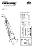
VS 14 / VS 18
To
1. Do not leave appliance when plugged in. Unplug from outlet when not in use and before servicing.
2. Do not use outdoors or on wet surfaces.
3. Do not use near small children. Do not allow to be used as a toy. Close attention is necessary when used
by or near children.
4. Use only as described in this manual. Use only manufacturer's recommended attachments.
5. Do not use with damaged cord or plug. If appliance is not working as it should, has been dropped,
damaged, left outdoors, or dropped into water, return it to a service center.
6. Do not pull or carry by cord, use cord as a handle, close a door on cord, or pull cord around sharp edges or
comers. Do not run appliance over cord. Keep cord away from heated surfaces.
7. Do not unplug by pulling on cord. To unplug, grasp the plug, not the cord.
8. Do not handle plug or appliance with wet hands.
9. Do not put any object into openings. Do not use with any opening blocked; keep free of dust, lint, hair,
and anything that may reduce air flow.
10. Keep hair, loose clothing, fingers, and all parts of body away from openings and moving parts. Do not
place fingers or other body parts under vacuum unless unplugged.
Do not pick up anything that is burning or smoking, such as cigarettes, matches, or hot ashes
12. Do not use without dust bag and/or filters in place.
13. Turn off all controls before unplugging.
14. Use extra care when cleaning on stairs.
15. Do not use to pick up flammable or combustible liquids such as gasoline or use in areas where they may
be present.
16. Machines can cause a fire when operated near flammable vapors or materials. Do not operate this
machine near flammable fluids, dust or vapors.
17. Maintenance and repairs must be done by qualified personnel.
18. Connect to a properly grounded outlet only. See Grounding Instructions.
19. Do not use machine as a step.
20. If used on plush carpet or carpet with thick padding, do not leave machine in one place with machine
turned on.
This appliance must be grounded. If it should malfunction or breakdown, grounding provides a path
of least resistance for electric current to reduce the risk of electric shock. This appliance is equipped
with a cord having an equipment-grounding conductor and grounding plug. The plug must be inserted
into an appropriate outlet that is properly installed and grounded in accordance with all local codes
and ordinances.
Improper connection of the equipment-grounding conductor can result in a risk of electric shock.
Check with a qualified electrician or service person if you are in doubt as to whether the outlet is
properly grounded. Do not modify the plug provided with the appliance if it will not fit the outlet,
have a proper outlet installed by a qualified electrician.
This appliance is for use on a nominal 120-volt circuit, and has a grounded plug that looks like the
plug illustrated ‘in sketch A. A temporary adaptor that looks like the adaptor illustrated in sketches
and C may be used to connect this plug to a 2-pole receptacle as shown in sketch if a properly
grounded outlet is not available. The temporary adaptor should be used only until a properly grounded
outlet (sketch A) can be installed by a qualified electrician. The green colored rigid ear, lug, or.
the like extending from the adaptor must be connected to a permanent ground such as a properly
grounded outlet box cover. Whenever the adaptor is used, it must be held in place by a metal screw.
Note: In Canada, the use of a temporary adaptor is not permitted by the Canadian Electrical Code.
Accidents due to misuse can only be prevented by those using the machine. To guard against injury, basic safety
precautions should be observed, including the following:
Read and follow all safety instructions.
WARNING: ELECTRIC SHOCK COULD OCCUR IF USED
OUTDOORS OR ON WET SURFACES
This vacuum cleaner is designed to be safe when used to perform cleaning functions. Should damage occur to
electrical or mechanical parts, cleaner should be repaired by WINDSOR or competent service station before
using in order to avoid further damage to machine or physical injury to user.
A damaged power cord could cause electrical shock and/or fire. To minimize this possibility observe the
following precautions:
Do not run cleaner over power cord.
Avoid closing doors on power cord, pulling it around sharp edges, or placing sharp-edged objects
upon it.
Wind cord no tighter than is necessary to retain it on the cord hooks.
When disconnecting power cord from electrical outlet, grasp the plug. Pulling it out by the cord itself
can damage cord insulation and internal connections to plug.
Your vacuum cleaner creates suction and contains a revolving brush. To avoid bodily injury from suction or
moving parts, vacuum cleaner brush should not be placed against, or in close proximity of loose clothing, jewelry,
hair or body surfaces while cleaner is connected to electrical outlet. Cleaner should not be used to vacuum
clothing while it is being worn. Keep children away from machine when in operation or plugged in.
If used on plush carpet or carpet with thick padding, turn off unit when handle is in upright position. When using
accessory tools, keep floor brush off carpet by keeping handle in locked position and lowering handle with one
hand to raise brush off floor. Operate accessories with other hand.
Always plug your cleaner into a standard wall outlet. Use of extension cord or light socket with inadequate currentcarrying capacity could result in electric shock or fire hazard.
Disconnect cleaner from electrical outlet before servicing, such as changing bags or belts. You could receive
bodily injury from moving parts of machine should switch accidentally be turned on. Disconnect cleaner from
electrical outlet before detaching powerhead.
Do not use your vacuum cleaner in areas where flammable and/or explosive vapor or dust is present to avoid
possibility of fire or explosion. Some cleaning fluids can produce such vapors. Areas on which cleaning fluids
have been used should be completely dry and thoroughly aired before being vacuumed.
To avoid fire hazard, do not pick up matches, fireplace ashes, or smoking material with cleaner.
Keep your work area well lighted to avoid picking up harmful materials (such as liquids, sharp objects, or burning
substances) and avoid tripping accidents.
Use care when operating the cleaner on irregular surfaces such as stairs. A falling cleaner could cause bodily
injury and/or mechanical damage. Proper storage of machine in an out-of-the-way area immediately after use will
also prevent accidents caused by tripping over cleaner.
Store your vacuum indoors in a cool, dry area not exposed to the weather to avoid electrical shock and/or
cleaner damage.
Exercise strict supervision to prevent injury when using vacuum cleaner near children or when child is allowed to
operate vacuum cleaner. Do not allow children to play with vacuum cleaner and never leave cleaner plugged in
and unattended.
SAVE THESE INSTRUCTIONS
Vacuum motor housing
Dustbag housing
Suction hose
On off switch
Cables cleats
Carrying recess
Back cover
Power head
Preparation
Assembling the vacuum cleaner
Hold the vacuum section in the vertical
position and insert into the power head.
Locate the line (13) on the motor housing
accurately opposite the rib on the swivel
neck (14). The locking catch (15) must be
turned to the left during the locating. Secure
the vacuum section in place the turning the
locking catch to the vertical position.
Attaching suction hose
Push the black end of the hose into the
connecting tube (12) so that it clicks into
place. To disconnect the hose press the
retaining ring (11) and pull the hose out of
tube.
Swivel neck latch
To release the machine from the upright
position depress the foot pedal (16).
Power head on
Power head motor stops automatically when
hand nozzle (17) is withdrawn and restarts
automatically when reinserted. If power head
does not start check that hand nozzle is fully
inserted.
Brush controller
The electronic brush controller monitors the
operation of the brush.
Green light: Brush correctly set and running.
Green light and red light: Adjust the brush
setting by turning the Pile adjustment knob
(19) to a lower number.
If the lights still show at position number one
the brush strip is worn out and must be
replaced.
Red light: The brush has become blocked
and is not turning. Switch off. Unplug from
the outlet and clear the blockage.
Filter level indicator
If warning light (18) comes on check:
a) Is the dust bag full?
b) Is there a blockage in the hose or power
head ?
Maintenance
CAUTION Always unplug machine at mains outlet before dismantling any part of the machine.
For guarantee use only genuine
Windsor-Parts (e.g. Filter Bags,
Filters, Brush strip, etc.)
Changing the paper bag
To change the dust bag: Remove back cover.
Push down lever (20). Lower dust bag from
connecting tube. Close aperture of dust bag
top with cardboard cover (21 A). To fit new
dust bag: Insert top of dust bag (21) into slot
(22). Push lever (20) down and fit
aperture of dust bag top over connecting
tube. Return lever so that it is in horizontal
position.
Changing filters
Vacuum motor filters (23) Replace after ca.
20 paper bags have been used.
Exhaust filter (24) Change when it becomes
dirty.
Press the button (25) and pull the filter forwards. To insert a new filter, locate the filter
into the motor housing and push up until the
button (25) engages into place.
Clearing blockages
If the bag-full warning light shows before the
dust bag is full check for blockages. Release
the hose by squeezing the tabs of the
retaining ring (11). Reverse the hose and put
the wand-end into the connecting tube (12).
Remove the obstruction by switching on the
machine, holding the hose upright. If
necessary rapidly lift your hand on and off
the end of the hose. Never use a stick to
clear the hose.
Changing the brush strip
To replace brush strip: Remove brush strip
cover (26). Turn brush roller so that the brush
strip can then be pulled out. Ensure that the
new brush strip is fully inserted.
N.B. Replace the brush strip before the bristles wear down to the level of the support rod.
Service Instructions
Maintenance
CAUTION Maintenance and repairs must be
done by qualified personnel.
WARNING To reduce the risk of electric shock
unplug before cleaning or servicing.
Entretien
32
The switch housing cover is removed by taking out the three screws
then lifting off. Circuit board (33) can be removed by loosening
screw (32).
To remove the dust bag housing (2) from the
vacuum motor housing (1) take off the back
cover and remove the four large screws.
Keeping the power head attached, the dust
bag housing can be eased off.
To remove the vacuum motor, first detach the
two black wires from the terminal block.
When replacing ensure that the motor support is fully located onto the motor cover.
The motor cover should then be firmly located onto the vacuum motor and the motor,
with its cover and support, firmly seated into
position as shown in the vacuum motor
housing.
When properly seated the motor cannot be
turned. Replace motor seal.
To remove the power head cover, take off the
brush strip cover (26) and remove the four
large screws (27) from underneath the
chassis. The cover can then be lifted off.
26
Changing the brush roller:
Push the belt (29) off the motor pulley (30)
and remove the four screws which hold in
the brush bearing blocks. Lift out the bearing
blocks evenly. When replacing the roller with
the bearing blocks, push downwards keeping
the roller parallel with the chassis.
To remove the brush roller pulley (31) hold
the roller in one hand and turn the pulley in a
clockwise direction.
To remove the motor pulley (30) insert a
screwdriver into a groove and give a light tap
in an anticlockwise direction. The loosened
pulley can then be removed.
Changing the Electronic Controller (34):
Disconnect the lead from the motor. Lift the
controller upwards from the motor. Lift the
controller upwards from its location and then
disconnect the lead from the swivel neck.
To remove the swivel neck
take out the
two small screws (36) from the swivel neck
supports (37) then lift the swivel neck
assembly from the chassis. On re-assembly
check that the leads from the swivel neck do
not become trapped when the power head
cover is replaced.
To remove the swivel neck cover, take out
the retaining screw (38) and slide the cover
(39) downwards then lift out. On re-assembly
check that the leads do not become trapped.
To remove the axle assembly unscrew the
three screws and take off the axle clamps.
Before replacing, lightly grease the axle.
To replace, hook one end of the spring on
the axle then grip the other end with a pair of
pliers and turn about a quarter of a turn.
Keeping the wheels at the ends of the axle
press the axle assembly black into place.
Description
Pos.
Code
1
13
14
15
16
17
18
19
20
21
22
23
24
25
26
27
28
29
30
31
32
33
34
35
36
37
38
1910
1918
1037 EH
1596 hg
1794
1949 bl
1420 hg
1548 hg
1038 bl
1792 hg
0517
1280
1069 UL
1477
1281
0818
1283 UL
1030
1026 UL
1040
1041
1027
1025
1073
1044
1534 hg
1139 bl
1059
1061
1057 BL
1461 bl
1462 BL
1517 hg
1516 hg
1797 WI
1521 hg
1798 dg
1896
1553
0819 dg
1887 UL
39
40
41
42
43
44
45
46
47
48
49
50
51
0511/1
1821 UL
1411
1047
1545
1265 UL
1524
0101
0102
0103
0111
0140
1034 hg
2
3
4
5
6
7
8
9
10
11
12
Cable
14)
18)
Cable
Handle grip
Handle cover
Handle
Dust bag housing
Grommet
Switch button
Connecting tube
Retaining ring
Switch
Switch cover
Switch holder
Prited circuit board
PC-board cover
Antistatic wire
Internal cable
Cable clamp
Switch housing cover
Dust bag lever
Return spring
Leaf spring
Connecting rod
Clamp
Motor filter
Exhaust filter
Back cover
Back cover seal
Gasket
Latch with spring and pin
Cable hook
Cable hook,
Hand nozzle
Hose
Motor housing
Housing cover r. h.
Filter retaining button
Sound insulation
Locking rod
Locking catch
Vac motor 120V / 1000W/
lamb
Carbon brush set vac mot.
Motor cover
Motor support
motor seal
Contact holder 3-wire
Terminal block 3-wire
Terminal block cover
x
DIN 7981
Screw C
x 13 DIN 7981
Screw F
x 16 DIN 7981
Screw C
Screw AM5 x 30 DIN 7985
DIN 125
Washer
Retaining ring
Pos.
100
101
102
103
104
105
106
107
108
109
110
111
112
113
114
115
116
117
118
119
120
121
122
123
124
125
126
2635 WI
2542
2543 BL
2522 hg
2539 dg
2525
2528 or
2010
2012 DG
2014
2622 dg
4019
2524
4072 dg
2510 HG
2541 UL
2546
2534
2530 HG
2538
2030 ER
2046
2091
2458
2047
2241 UE
0512/1
127
128
129
130
131
132
133
134
135
2025
4024
2572 ER
2531 hg
2545
0102
0103
0174
0111TL
Cover assembly
Brush strip cover
Chassis, cpl.
Bumper
Axle assembly
Axle, only
Foot pedal
Axle spring
Wheel and end clip
Axle clamp
Pile adjustment knob
Spring
Pile adjustment axle
Pile adjustment wheel
Swivel neck assembly
Wire, swivel neck
Leaf spring
Control lever
Swivel neck cover
Swivel support
Brush assembly, cpl.
Brush strip
Bearing block I. h.
Brush roller pulley
Bearing block r. h.
Brush motor 120 150 W
Carbon brush set
brush motor
Motor pulley
Drive belt
Electronic control PC-board
Support lever
Return spring
x 13 DIN 7981
Screw F
Screw C
x 16 DIN 7981
x 22 DIN 7981
Screw C
Screw AM5 x 30 DIN 7985
Pos.
Description
100
101
102
103
104
105
106
107
108
109
110
111
112
113
114
115
116
117
118
119
120
121
122
123
124
125
126
127
4547 WI
2542
4529 BL
4522 hg
4519 dg
4523
2528 or
2010
4009 DG
2014
2622 dg
4012
4019
4006
4072 dg
2510 HG
2541 UL
2546
2534
2530 HG
2538
4033 ER
4028
2091
2458
2047
4022 UE
0512/1
128
129
130
131
132
133
134
135
136
2025
4024
4532 ER
2531 hg
2545
0102
0103
0174
O111TL
Cover
Brush strip cover
Chassis, cpl.
Bumper
Axle, cpl.
Axle only
Foot pedal
Axle spring
Wheel and end clip
Axle clamp
Pile adjustment knob
Pile adjustment lever
Spring
Pile adjustment axle
Pile adjustment wheel
Swivel neck assembly
Wire, swivel neck
Leaf spring
Control lever
Swivel neck cover
Swivel support
Brush assembly
Brush strip
Bearing block h.
Brush roller pulley
Bearing block r. h.
Brush motor 120 200 W
Carbon brush set
brush motor
Motor pulley
Drive belt
Electronic control PC-board
Support lever
Return spring
x 13 DIN 7981
Screw F
Screw C 3,9x 16 DIN 7981
x 22 DIN 7981
Screw C
Screw AM5 x 30 DIN 7985
Technical Details VS 14
Voltage
Vacuum floor
Air flow
Dust bag
Brush motor
Brush width
Brush drive
Brush strip
Height
Width
Weight
120 volt, 60 hz
amp.
117cm
gal., 3-layer
(1 ,a) amp.
12
(16
inches
non slip drive belt
with electronic
overload protection
replaceable
46 inches
14 (16) inches
16 (16) Ibs
Details Techniques VS 14
1351 West Stanford Ave.
Englewood, Colorado 80110 USA
800-444-7654
303-762-1600
FAX:
06397 11/99