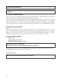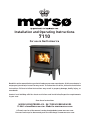
1
Installation and Operating Instructions
7110
For use in North America
Read this entire manual before you install and use your new room heater. If this room heater is
not properly installed, a house fire may result. To reduce the risk of fire, follow the installation
instructions. Failure to follow instructions may result in property damage, bodily injury, or
even death.
Contact local building officials about restrictions and installation/inspection-requirements
in your area.
Save these instructions
MORSØ JERNSTØBERI A/S . DK-7900 NYKØBING MORS
E-Mail: [email protected] · Website: www.morsoe.com
A French version of the manual can be downloaded at www.morsona.com
Une version française du manuel peut être téléchargé à www.morsona.com
1
We congratulate you on your choice of a Morsø stove. Morsø has been
producing some of the world’s best stoves since 1853. If you follow this
installation- and operating instruction carefully, we can assure you
many years of warmth and pleasure.
Optional Accessories
A wide range of accessories (such as handling gloves, fireside tools, glass cleaner and heatproof
paint) are available for use with your Morsø stove. They help with day-to-day running and
maintenance. Contact your Morsø dealer for more information.
The Morsø 7110 meets the U.S. Environmental Protection Agency’s emission limits for wood
heaters sold on or after July 1, 1990
The Morsø 7110 have been tested by OMNI-Test Laboratories, Inc. The test standards are ANSI/
UL-1482 for the United States and ULC S627 for Canada.
The stove is listed for burning wood only. Do not burn other fuels.
Under specific test conditions this heater has been shown to deliver heat at rates ranging from
11,000 to 25,000 Btu´s.
Cast iron
Cast iron is a live material. There are no two ovens that are identical. This is partly due to the
tolerances of the casting process, partly because the ovens are a work of craftsmanship.
Minor unevennesses may also occur in the cast iron surface.
2
CONTENTS:
1.0
Installation of your Morsø stove
1.1
Checking loose parts in the stove
1.2
The chimney / flue system
1.3
Flue Connection
1.4
Connection to existing chimney
1.5
Positioning the stove
1.6
Mobile Home Installation
4
4
5
6
6
8
9
2.0
Operation
2.1
Before you start firing
2.2
Lighting and loading intervals
11
11
12
3.0
Maintenance
3.1
Exterior maintenance
3.2
Internal maintenance
3.3
Cleaning the Stove and the Flue
3.4
Leaving the stove for extended periods
3.5
Parts diagram
3.6
Parts list
16
16
16
18
20
21
22
3
1.0 Installation of your Morsø stove
Installation of woodburning stoves must be safe and legal.
If your Morsø stove is not installed correctly, it may cause a house fire. To reduce
the risk of fire, the installation instructions must be followed carefully. Contact the
local building officials about restrictions and installation inspection in your area.
Before you start installing your stove, make sure that:
- The stove and chimney connection are placed far enough from combustible materials to meet all clearance requirements.
- The floor protection must be adequate and must be made correctly according to ´the
requirements.
All neccessary approvals are needed from the local building officials.
The data plate, which is located on the back of the stove, provides information regarding safety
testing information, name of certified testing laboratory, and installation requirements.
Installation requirements vary in different districts, and the local building officials have the final
authorization to approve your installation. You should discuss the installation with them before
beginning. Please ask your dealer for further information.
Do not connect to any air distribution duct or system.
Important: If the installation instructions are not followed carefully, it may cause
dangerous situations like chimney - and house fires. Follow the instructions
carefully and do not deviate from them as it may cause injuries to people or
property.
1.1 Checking loose parts in the stove
After unpacking, check that the fire bricks are firmly in position and have not shifted in transit.
Check also that the air control works freely.
See separate Assembly Instructions for Legs, Fitting for handle, and Baffles
Before starting the initial fire, place the two cast iron baffles above the three stainless pipes
that supplies the secondary air. The baffles are enclosed in the stove on delivery. Afterwards,
place the carbowool blanket carefully above the two cast iron baffles.
Make sure that the upper heating shield, the cast iron baffles, and the carbowool blanket are
placed correctly before the fire is started.
Standard Accessories
A Morsø glove and ceramic flue connection gasket are standard accessories that usually can be
found in the ashpan or firebox area.
4
1.2 The chimney / flue system
Note that the flue system must be independently secured and must not rely on the stove for
support.
The stove must not be connected to a chimney flue serving any other appliance.
(Several flues may run up a single chimney stack; use one flueway per appliance).
Use a residential type masonry or listed type HT factory-built chimney.
High Temperature (H.T.) Chimney Standard UL-103-1985 (2100º F.) or a code-approved
masonry chimney with flue liner for the USA, and High Temperature (650ºC) Standard ULC
S-629 for Canada.
The internal dimensions of the chimney connector and chimney must not be less than 6 inches
diameter (or equivalent cross section), and should not be significantly larger than this. Too
large a section will tend to allow the flue gases to cool excessively, causing sluggishness or
unpredictability in the stove’s performance.
We recommend the length of the chimney system should be at least 16 feet (not required) above
the stove in normal domestic situations, measured from the flue collar to the top of the chimney.
Local conditions like for example - roof constructions, large trees nearby and high altitude, may
influence the chimney draft and height. Therefore, contact the local professional chimney sweep
or your Morsø dealer.
Typical Factory-Built or Masonry Chimney Installations
5
1.3 Flue Connection
The stove is supplied from the factory with a flue collar fitted to the top plate and a round blanking
plate blocking off the rear flue exit (behind the rear shield plate).
Use a 24 MSG black or blue chimney connector or listed double wall chimney connector. Refer
to local codes and the chimney manufacturer’s instructions for precautions required for passing
a chimney through a combustible wall or ceiling. Remember to secure the chimney connector
with a minimum of three screws to the product and to each adjoining section.
The collar can be fitted to the rear outlet. Simply knock out the round panel on the rear heat
shield plate to reveal the cast iron plate. Untwist the blanking plate and the flue collar and swap
their positions. Re-secure by pushing down and tighten the enclosed screws.
Position the stove and connect to the flue system.
Wear gloves and protective eyewear when drilling, cutting or joining sections of chimney
connector.
1.4 Connection to the existing chimney
A chimney connector is the double-wall or single-wall pipe that connects the stove to the chimney.
The chimney itself is the masonry or prefabricated structure that encloses the flue. Chimney
connectors are used only to connect the stove to the chimney.
Double-wall connectors must be tested and listed for use with solid-fuel burning appliances.
Single-wall connectors should be made of 24 gauge or heavier gauge steel. Do not use galvanized
connector; it cannot withstand the high-temperatures that smoke and exhaust gases can reach,
and may release toxic fumes under high heat. The connector must be 6 inches (150mm) in diameter.
If possible, do not pass the chimney connector through a combustible wall or ceiling.
If passage through a combustible wall is unavoidable, refer to the sections on Wall
Pass- Throughs. Do not pass the connector through an attic, a closet or similar
concealed space when installing the chimney connectors.
It is important to keep the flue gases moving smoothly in the right direction. Do not vent into a
large void at this location; rather form one continuous section all the way up. Use mild bends
(e.g. 45º vs. 90º) rather than sharp angles where a change of direction is required. All parts of
the venting must be accessible for cleaning purposes.
In horizontal runs of chimney, maintain a distance of 18 inches from the ceiling. Keep it as
short and direct as possible, with no more than two 90 degree turns. Slope horizontal runs of
connector upward 1/4 inch per foot (20 mm per metre) going from the stove toward the chimney.
The recommended maximum length of a horizontal run is 3 feet (1 metre), and the total length
should be no longer than 8 feet (2.5 metres).
Information on assembling and installing connectors is provided by the manufacturer’s instructions
exactly as you assemble the connector and attach it to the stove and chimney.
Be sure the installed stove and chimney connector are correct distances from near by
combustible materials. See the clearance paragraph page 8.
Where passage through a wall or partition of combustible construction is desired, the installation shall conform to CAN/CSA-B365.
6
7
1.5 Positioning the stove
Distance to walls and lintel
When the stove is positioned near combustible materials, observe all current local and national
building regulations with regards to clearances. Whatever regulations apply to your area, do
not in any case install the stove within 8 inches of combustible materials around the sides or
16 inches above the top of the stove (fireplace installations require greater clearances above
the stove - see below in the clearance chart). These distances may need to be increased if the
materials are sensitive to heat. Note also that wall paper and other decorative materials may
become detached with the effects of heat and care should be taken to ensure that they do not
fall towards the stove in such an event.
When the stove is positioned near non-combustible materials, a gap of 4 inches or more is
recommended for cleaning purposes and to ensure that heat circulates around the stove and
out into the room.
If using rear exit, the floor protection must extend beneath the chimney connector and 2-in
beyond each side.
8
Distance to furniture
The recommended minimum distance from stove to furniture is 30 inches. Note that some
furniture is more easily affected by heat and may need to be moved to a greater distance. This
is your responsibility.
In addition other combustible materials, away from the stove. In general, a distance of 30 inches
must be maintained between the stove and moveable combustible item such as drying clothes,
newspapers, firewood etc.
1.6 Mobile Home Installation
The Morsø 7110 can be installed in a mobile home if equipped with an outside combustion air
kit, a terminal cap with a spark arrestor, and if it meets the following installation requirements:
•
The stove must be secured to the mobile home structure by bolting through the
hearth pad and into flooring.
•
The stove must be installed with a listed Type HT chimney connector, HT Chimney,
and terminal cap with spark arrestor. Never use a single wall connector (stovepipe)
in a mobile home installation.
•
Floor protection requirements in section 1.5 must be followed precisely.
•
In Canada, this appliance must be connected to a 6” (152 mm) factory-built chimney
conforming to CAN/ULC-629M, STANDARD FOR FACTORY BUILT CHIMNEYS. Floor
protection as referenced in section 1.5 must be followed, as well as use of Canadian
Floor Protector.
•
Follow the chimney and chimney connector manufacturer’s instructions when installing the flue system for use in a mobile home.
•
Outside air kit should be installed according to installation guide in the kit.
•
Intake air piping can be installed through the floor into a vented crawl space or
through the wall of the residence to obtain outside air.
•
Install in accordance with 24 CFR, Part 3280 (HUD).
•
NOTE: Top sections of chimney must be removable to allow maximum clearance of
13.5’ from ground level for transportation purposes.
WARNING:
NEVER DRAW COMBUSTION AIR FROM A WALL, FLOOR OR CEILING CAVITY OR FROM ANY
ENCLOSED SPACE SUCH AS AN ATTIC OR GARAGE.
DO NOT INSTALL IN A SLEEPING ROOM.
9
CAUTION:
THE STRUCTURAL INTEGRITY OF THE MOBILE HOME FLOOR, WALL, AND CEILING/ROOF MUST
BE MAINTAINED (I.E., DO NOT CUT THROUGH FLOOR JOIST, WALL STUD, CEILING TRUSS, ETC.)
DO NOT USE A GRATE TO ELEVATE FIRE - BUILD FIRE DIRECTLY ON HEARTH.
Note:
Acid Protection
If acid-washing the masonry around the stove, protect the stove surface with an acid-proof
cover
Fresh Air Inlet
Unless there is deemed to be sufficient ambient leakage of air into the room via doorways,
windows and the like, a dedicated fresh air inlet will be needed. This inlet should have 2 square
inches (1250 square mm) of free air space. This is particularly important where the room is
well sealed, or where an extractor hood or ventilation system disturbs the natural air pressure. Such an inlet should not be on a wall that is usually subject to negative pressure from
normal wind pattern. Avoid placing the inlet directly across the room from the stove, thus
causing a cold air draft.
10
2.0 Operation
2.1 Before you start firing
For Use with Solid Wood Fuel Only. Do Not Overfire, If Heater or Chimney Connector
Glows You Are Overfiring. Inspect and Clean Chimney Frequently. Under Certain
Conditions of use creosote buildup may occur rapidly. Because of risk of smoke and flame
spillage, operate only with door fully closed.
Caution:
Hot while in operation. Keep children, clothing and furniture away. Contact may cause
skin burns.
Do not use chemicals or fluids to start the fire.
Do not burn garbage or flammable fluids.
Do not use gasoline, gasoline-type lantern fuel, kerosene, charcoal lighter or fluid or similar
liquids to start or freshen up a fire in this heater. Keep all such liquids away from the heater
while it is in use.
Choosing your fuel
All types of natural wood can be burned on your stove, but they must be well-seasoned and dry.
Once the wood is cut to length, it should be split down middle - to suit the dimensions given
below - to allow moisture to evaporate.
Cut the wood to a length of max 18 inches (45 cm) and approx. 3 to 3.5 inches (7-8 cm) in section.
If you can weigh your wood, aim for around 2 lbs. For correct combustion and heat output, wood
fuel should contain no more than 20% moisture; this can easily be checked by using the Morsø
Moisture Meter (part # 62929900)
To naturally season wood fuel, stack and store it under cover in an airy location where fresh air
can move through each piece. Some soft woods may take as little as one good summer to season
whereas harder woods such as oak, maple, and elm may require seasoning up to 18 months.
Avoid overly dry wood that is gray in color as under certain conditions it can cause performance
problems, such as back-puffing and sluggishness. Well seasoned wood will be light to hold and
will show signs of cracking from the center-out in the ends. If your wood spits or sizzles when
burnt, and your stove’s door glass persistently mists up, your wood is not properly seasoned.
Never use drift wood (from the sea), whose salt content may cause corrosion, nor construction
wood that may have been impregnated with chemicals.
Caution: Do not place fuel within the installation clearances for the stove or within the space
required for loading fuel and ash removal.
Starting the First Fire
The initial fire should be small, so that the stove paint can cure and the main plates of the stove can
settle into position. Some fumes will be given off by the paint. Ventilate the room during this phase.
The setting of the air control, lighting techniques and loading intervals will depend on chimney
draft, the fuel used, the heat required and so on. Some basic techniques are outlined below.
In principle
Your stove is fitted wih Primary and Secondary air inlets.
Primary Air is controlled using the lever situated under the ash lip of the stove. Moving the
11
control lever to right position will open the air inlet and will allow a supply of preheated air to
enter the firebox via the ‘airwash’ system situated inside the stove and the above glass.
Secondary Air is left to the firebox using the specially designed baffle at the back of the firebox.
The secondary air is injected into the flue gases above the fire resulting in a cleaner, more efficient
combustion process. The supply of secondary air is fixed open and is not adjustable.
For extra safety, your stove has been fitted with a removable handle.
2.2 Lighting and loading intervals
When first lighting the stove, a large volume of air is needed. When the stove is cold, you should
leave the door open an inch or two for the first few minutes and open the primary air
supply completely. While the door is open, do not leave the stove unattended.
The ash door should never be open while the stove is in operation.
To form a reasonable bed of ash on the floor of the stove, you should use 5-6 inches thickness
(2-4 pound) of dry kindling at the initial lighting. Always maintain a 1-1.5 inch (2-3 cm) layer of
ash on the floor of the combustion chamber at all other times.
Step-by-step procedure
1. A layer of embers will form rapidly if the stove
is lit with 2 - 4 fire lighters or 7 - 10 rolled up
sheets of newspaper, underneath roughly 1-2
kg of dry kindling.
2. Fully open the secondary air supply that is
controlled by lever beneath the ash lip.
3.
12
Light the fire.
4. After the paper/fire lighters have caught fire,
leave the fire door ajar about 2-3 cm, so that
the chimney draws well.
5. After 5-10 minutes the chimney draft should
be established, at this point close the fire door.
If all the necessary conditions are met, a nice
layer of embers will start to accumulate after
another 15 - 20 minutes.
6. Refuelling of your stove should be done while
there are still glowing embers in the bed.
Spread the embers across the bottom, but
concentrated mostly towards the front of the
stove.
When refuelling your stove, it is recommended that you open the stove door gently for the first
2 - 3 centimetres, then wait for a few seconds for the pressure in the flue to equalise; you are now
safe to proceed and open it all the way. By using this technique smoke spillage can be eliminated
particularly in poor chimney draft conditions. The stove door should not be opened when the
stove is being fired vigorously.
13
7. Place two pieces of fuel weighing roughly 2-4
pound and measuring about 25 cm in length
across the embers in one layer, with spacing
of roughly 1 cm between the pieces of wood.
8. When the primary air supply is opened all the
way and the door is closed, the new fuel will
ignite in a few minutes.
9. Once the new fuel has taken, adjust the
secondary air amount to the desired setting;
optimal combustion will continue until
glowing embers are produced.
Under normal chimney draft conditions,
expect to refuel your stove every 60 - 70
minutes.
10. A new charge of wood can be added by repeating steps 6 & 7.
14
Do not for any reason attempt to increase the firing of your heater by altering the air
control adjustment range outlined in these directions.
Warning: Fireplace stoves must never be left unattended with doors open.
If doors are left partly open, gas and flame may be drawn out of the fireplace stove
opening, creating risks from both fire and smoke. We recommend you to fit a smoke detector
in the room where the stove is installed.
DO NOT OVERFIRE THIS HEATER. Overfiring may cause a house fire, or can result in
permanent damage to the stove. If any part of the stove glows, you are overfiring.
The maximum recommended weight of wood fuel per load is 2.5 kg/h/5.5Ibs (approx 3 split logs).
Under normal firing, the average flue temperature in the stove pipe, measured 20 cm above
the stove, is approx. 300° C (550°F). The maximum flue temperature in the stove pipe must not
exceed 450° C (750°F). If the flue temperature exceeds 450°C (750°F), it is considered as over
firing and may cause premature wear and tear of the stove.
To help gauge the correct running temperature of your stove, we recommend you use the Morsø
Flue Gas Thermometer (part # 62901200). The Flue Gas Thermometer magnetically attaches
onto the stove pipe approx 20 cm (8”) above the stove’s top plate and measures the surface temperature of the stove pipe. Please see your authorized Morsø Dealer for availability.
Draft conditions
If smoke or fumes come out of your stove when lightning up and reloading, or if the fire simply
will not respond, a poor draft is almost certainly to blame. (In a very few cases, there may be
insufficient fresh air getting into the room - see installation advice above). Take advice from your
stove supplier on how best to upgrade your flue system to improve draft.
Rules of woodburning
If you want less heat, put fewer logs on the stove and reduce the amount of air. It is still important
to maintain a good layer of embers.
Less heat - less wood - less air
Greater heat - more wood - more air
Soot deposits will settle on the glass if the stove is run too slowly or if your wood is not well seasoned.
15
3.0 MAINTENANCE
When perfoming maintenance on your stove, always protect yourself, using safety goggles
and gloves
3.1 Exterior Maintenance
The stove surface is painted with heat-resistant Senotherm paint. It is best kept clean by vacuuming
with a soft brush attachment or by wiping with a lint-free cloth.
Over a period of time, the painted surface may become slightly grey. A can of Morsø touch-up
spray paint should be available from your stove supplier. This can be applied - in accordance
with the instructions - in just a few minutes. When first firing after touching up, the stove will
give off a slight smell as the paint cures. Make sure to ventilate the room well during this phase.
3.2 Internal maintenance
Glass
If the stove is generally run at the correct temperatures, there should be little or no dirt on the
glass. If dirt does settle during lighting, most will burn off as temperatures increase.For heavier
deposits that will not burn off, use morsø glass cleaner, applied when the glass is cold, in
accordance with the instructions. Never use abrasive cleaners on the glass surface.
Reasons for dirty glass
· Fuel too wet
· Logs too large or not split
· Combustion temperatures too low
Replace broken glass immediately.
Do not operate your stove if the glass in the door is damaged.
If you need to replace the glass, it should be replaced with the high temperature ceramic class
supplied by Morsø, contact your Morsø dealer.
Installing the glass
Never install the glass when the stove is in function.
16
Ceramic glass replacement
Ceramic glass cannot be recycled because it has a higher melting point that ordinary glass. If
ceramic glass is mixed with ordinary glass, the raw material is spoiled, and the reclaiming process may be halted. Take care that the ovenproof glass does not end up among ordinary recycled
waste. That will be a great benefit to the environment.
Note: Should be handed in to a recycling station as ceramic glass.
1. When you open the door, you will find two small M4 unbraco screws, one in each hinge.
Unscrew the two screws, lift the door off the hinges and place it face down on a sheet of
cardboard or other nonabrasive fabric.
2. Unscrew the 4 bolts that secure the glass. (In the event that a bolt sheers off when being
unscrewed, remove the remaining body of the bolt by drilling down its centre with 1/8 inch high
speed steel drill bit. Smaller drill bits may be successful, but do not use a lager bit. Make sure
the bit stays away from the edges of the bolt - this may damage the thread in the cast iron).
3. Remove the old ceramic gaskets and clean up the surface underneath with wire wool or emery
paper to remove loose particles.
4. Place the new gasket material in position around the perimeter of the window area, making
sure to pinch them to the length in such a way that they make a continuous seal. Leave no gaps.
5. Place the new glass in position on the strips and screw home the fresh bolts and fitting by hand.
6. Finally, give each of the bolts an extra half turn or so. The glass should held tight enough by that
cleaning will not dislodge it. Do not over-tighten the bolts as this may put excessive pressure
on the glass, resulting in cracking - important!
17
To reduce the risk of breaking the glass, avoid striking the glass or slamming the
door.
Internal service parts
The flame-path equipment - consisting of the ashpan, grate, firebricks, Cast iron fire plates,
glass, baffle and flue collar - are subject to the extremes of heat produced by the fire. From
time to time, one or other of these parts may need replacing as a matter of routine maintenance.
NOTE: The flame-path equipment, the ceramic rope and the paint finish are not covered
by guarantee.
All of these service parts can be bought from your morsø dealer, and we recommend that damaged
parts are replaced as soon as possible to avoid collateral damage.
Should the baffle be distorted by an overfire, the stove will still function, although its efficiency
may be compromised. Replace it as soon as possible.
Reasons for fast internal wear and tear
Persistent heavy firing
Soot and ashes left to accumulate
Gasket
The gasket around the perimeter of the doors may harden over a period of time. It should be
replaced if it becomes difficult to close the doors or if air starts to leak in around the perimeter
of the doors, causing the fire to become a little less controllable. A morsø rope gasket kit is
available from your stove supplier.
3.3 Cleaning the Stove and the Flue
Check for soot above the baffle plate and around the flue outlet every month or so to start with.
If the stove suddenly becomes sluggish, check for a soot fall around the flue collar or in the flue/
chimney.
The chimney and chimney connector should be inspected at least once every two months
during the heating season to determine if a creosote buildup has occurred. If creosote has
accumulated, it should be removed to reduce the risk of a chimney fire.
Clean the flue/chimney - all the way from the stove to the flue terminal point above the house.
A good routine is to clean the flue after each heating season in any case, and inspect prior to the
season to ensure that bird’s nests or other blockages have not occurred during the off season.
Ash disposal
Empty the ashpan on a daily basis or as needed. Ash allowed to build up towards the underside
of the grate will trap heat and could cause premature failure of the grate.
Empty the ashpan according to this procedure:
Open the front door, and use a shovel or poker to stir excess ash through the ash slots in the
grate down into the ash pan. Then, open the ash door and take out the ash pan, making sure to
keep it level to avoid spilling ash.
18
Dispose the ash in a metal container with a tight fitting lid.
The closed container of ashes should be placed on a noncombustible floor or on the ground,
well away from all combustible materials, pending final disposal. If the ashes are disposed of
by burial in soil or otherwise locally disperded, they should be retained in the closed container
until all cinders have thoroughly cooled.
Return the ash pan to its original position in the stove, and close the ash door.
Caution:
Never empty a stove in operation.
Never use your household or shop vacuum cleaner to remove ash from the stove;
always remove and dispose of the ash properly.
Creosote - formation and need for removal
When wood is burned slowly, it produces tar and other organic vapors, which combine with expelled
moisture to form creosote. The creosote vapors condense in the relatively cool chimney flue of a
slow-burning fire. As a result, creosote residue accumulates on the flue lining. When ignited this
creosote makes an extremely hot fire. When burning wood, the chimney and chimney connector
should be inspected at least once every two months during the heating season to determine if
a creosote buildup has occurred. If creosote has accumulated, it should be removed to reduce
the risk of a chimney fire.
Chimney sweeping
Inspect the system regularly during the heating season as part of a regular maintenance schedule.
To inspect the chimney, let the stove cool completely. Then, using a mirror, sight up through the
flue collar into the chimney flue. If you cannot inspect the flue system in this fashion, the stove
must be disconnected to provide better viewing access.
Clean the chimney using a brush the same size and shape as the flue liner. Run the brush up
and down the liner, causing any deposits to fall to the bottom of the chimney where they can be
removed through the clean-out door.
Clean the chimney connector disconnecting the sections, taking them outside, and removing any
deposits with a stiff wire brush. Reinstall the connector sections after cleaning, being sure to
secure the joints between individual sections with sheet metal screws.
If you cannot inspect or clean the chimney yourself, contact your local Morsø Dealer or a
professional chimney sweep.
If you do experience a chimney fire, act promptly and:
Close the air control.
Get everyone out of the house.
Call the Fire Department.
Annual maintenance
Before the heating season, perform a thorough cleaning, inspection and repair:
Thoroughly clean the chimney and chimney connector.
Inspect the chimney for damage and deterioration. Replace weak sections of prefabricated
chimney. Have a mason make repairs to a masonry chimney.
Inspect the chimney connector and replace any damaged sections.
Check gasketing for wear or compression, and replace if necessary.
Check the glass for cracking; replace if needed.
Check door and handles for tightness. Adjust if needed.
19
3.4 Leaving the stove for extended periods
Important:
If the stove is to be left unused for any period of time, clean it out thoroughly and leave the air
control slightly open to allow airflow. Make sure that the flue does not allow rainwater to come
anywhere near the stove; install a chimney cap, but do not block off the flue completely.
These measures should ensure there is a slight movement of air through the stove, and that the
body of the stove remains dry, right into the corners.
Any ash left within an unfired stove can attract moisture like blotting paper. If moisture is allowed
to settle within the stove, rust will form. Rust expands as it takes a grip. This can lead to undue
pressure on the stove joints, and this in turn may result in damage to the stove.
NOTE: It is best to thoroughly clean the stove after the heating season has concluded. Adding
a dessicant, such as kitter litter, into the ash pan helps absorb moisture during the summer
months. Be sure to remove this prior to the heating season.
Thank you for buying a morsø stove.
We hope you have many years of carefree warmth in its company. Some initial experimentation
with loading and running techniques will decide your normal routine. If you have any problems
after this short learning phase, please refer to your stove dealer. Should they be unable to help
for any reason, please contact us in writing at the address on the front of this publication.
20
Date of print: 10-11-2010
92
5
77
84
3
64
47
62
94
62
64
77
84
58
34
93
42
33
96
53
34
91
93
95
42
95
42
83
7140
DIN
67
18
83
46
46
33
2
21
50
64
53
62
15
26
29
95
41
17
76
64
NA
53
77
12
50
34
64
10
33
59
44
65
64
89
69
88
64
60
80
75
64
30
66
14
46
63
28
79 50
50
48
25
86
53
54
64
85
54
50
64
27
64
64
59
53
65
64
96
33
37
78
30
64
73
71
64
78
50
74
23
74
56
61
61
32
24
16
36
96
33
59
64
53
66
68
73
72
70
7
50
35
9
1
82
56
61
13
52
64
53
31
64
64
11
50
64
8
Påført pos. 94 og 95.
Fjedersystem ændret.
h
g
Released:
Reservedelstegning
21
U:\udv\Tegninger\7100\7110 Samling.SLDASM
-
A2
7100-501 l
Drawing no.:
Itemno.:
Date:
19.08.03
KDU
19.08.05
14.06.2006
09.01.07
07.05.2008
19.02.2009
52
65
40
Sign.:
KDU
RSV
KDU
RSV
RSV
65
55
59
This drawing is Morsø Jernstøberi A/S' property and must no be sold, lended or copied without any written authorization from the company.
Location of file:
Drawingtype:
Model no.
Morsø 7110
Construction:
81
Title:
Rev. Revisions
Air kit som option og mont. af røgtude.
Påført pos. 95 ved askedør.
j
4
k
Ændret pos. på lille greb fra 87 til 89.
90
38
l
64
63
Format:
64
51
64
90
Option
Scale:
-
87
50
39
Weight:
20
64
63
Material:
19
6
22
33
3.5 Parts diagram for model Morsø 7110
3.6 Parts list for model Morsø 7110
Pos.No.
1
2
3
4
5
6
7
8
9
10
11
12
13
14
15
16
17
18
19
20
21
22
23
24
25
26
27
28
29
30
31
32
33
34
35
36
37
38
39
40
41
42
44
46
47
48
49
22
Parts
Base plate
Front frame
Door
Side plate, right
Side plate, left
Rear plate
Top plate
Rear air duct
Button air duct
Front air duct
Secondary air duct, right
Secondary air duct, left
Leg
Frame for ash door
Ash door
Grate
Locking device
Ceramic glass
Brick, back
Brick, side, right
Brick, side, left
Radiant shielding, rear
Radiant shielding, bottom
Ash tray
Primary damper
Handle
Brick fitting
Fitting for pin at ach tray
Screw
Secondary tube, big
Secondary tube, litle
Cover
Flue collar
Fitting w. thread for flue collar
Fitting for baffle plate
Distance tube
Distance tube
Distance tube
Distance tube
Air adaptor
Hinge pin
Hinge pin
Cotter pin
Cotter pin
Glass fitting
Screw
Screw
447101xx
447102xx
447103xx
447119xx
447120xx
447106xx
447107xx
447108xx
447109xx
447110xx
34711100
34711200
447113xx
447114xx
447115xx
34711600
797117xx
79710000
79710100
79710200
79710300
547101xx
547102xx
71710300
71710400
71710500
71710600
71710700
-
71710900
71711000
44261000
44344100
44256700
545006
545007
541439
542635
54710100
71360600
545008
54503000
791870
79187200
54146361
-
50
51
52
53
54
55
56
57
58
59
60
61
62
63
64
65
66
67
68
69
70
71
72
73
74
75
76
77
78
79
80
81
82
85
86
87
88
89
94
95
96
Screw
Screw
Screw
Screw
Screw
Screw
Screw
Screw
Screw
Screw
Screw
Washer
Washer
Washer
Washer
Screw
Baffle plate, cast iron
Tightening tape for glass
Insulation
Primary handle
Baffle plate, upper
Stop fitting, left, for baffle plate
Stop fitting, right, for baffle plate
Fitting for baffle plate
Screw
Nuts
Adaptor for handle
Screw
Screw
Fitting for primary handle
Screw
Fitting for handle
Fitting for leg
Locking fitting for sek. pipe
Screw
Washer
Clasp
Bakelite handle 36mm
Hinge pin
Washer
Stop bar
34711800
79074500
79710500
71711161
79710400
71711200
71711300
71711400
71710800
717115xx
717117xx
717118xx
71712061
74150804
736210
791270xx
79118200
74701000
544541
23
Morsø Jernstøberi A/S - 19.08.2013 - 72711000