1
Owner's Manual
ICRAFTSMAN°I
16.0 HP
ELECTRIC START
42" MOWER
AUTOMATIC
LAWN TRACTOR
Model No.
917.272067
• Safety
• Assembly
• Operation
• Maintenance
• Repair Parts
CAUTION:
Read and follow all Safety
Rules and Instructions before
operating this equipment.
For answers
to your questions
about this product, Call:
1-800-659-5917
Sears Craftsman Help Line
5 am - 5 pro, Mon- Sat
Sears, Roebuck and Co., Hoffman Estates, II 60179
Visit our Craftsman
website:www.sears.com/craftsman
MaintenanceSchedule......................18
Serviceand Adjustments....................23
Storage...............................................
29
Troubleshooting.................................
30
RepairParts........................................
34
PartsOrdering.....................BackCover
Warranty...............................................
2
SafetyRules .........................................
3
Product Specifications..........................
6
Assembly..............................................
8
Operation............................................
11
Maintenance.......................................
18
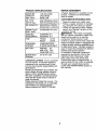
LIMITEDTWOYEARWARRANTYONCRAFTSMANRIDINGEQUIPMENTPARTS
Fortwo (2) yearsfrom the date of purchase,if this CraftsmanRidingEquipmentis
maintained,lubricatedand tuned up accordingto the instructionsin the owner's
manual,Searswill repair or replace,free of charge,any partsfoundto be defectivein
materialor workmanship.Warrantyserviceis availablefree of charge by returning
your Craftsmanriding equipmentto your nearestSearsServiceCenter. In-home
warrantyserviceis availablebut a trip chargewill apply.This warrantyappliesonly
whilethis productis usedin the UnitedStates.
This Warrantydoes not cover:
• Expendable
items which become worn during normal use, such as blades, spark
plugs, air cleaners, belts and oil filters.
• Tire replacement
or repair caused by punctures from outside objects, such as nails,
thorns, stumps, or glass.
• Repairs necessary because of operator abuse, including but not limited to, damage
caused by towing objects beyond the capability of the riding equipment, impacting
objects that bend the frame or crankshaft, or over speeding the engine.
• Repairs necessary because of operator negligence,
including but not limited to,
electrical and mechanical damage caused by improper storage, failure to use the
proper grade and amount of engine oil, failure to keep the deck clear of flammable
debris, or the failure to maintain the equipment according to the instructions
contained in the owner's manual.
• Engine (fuel system) cleaning or repairs caused by fuel determined
to be contaminated or oxidized (stale). In general, fuel should be used within thirty (30) days of its
purchase date.
• Riding equipment used for commercial or rental purposes. A product is "used for
commercial
purpose" if is used for any purpose other than single family household
dwellings or in usage where profit is made.
LIMITED
90 DAY WARRANTY
ON BATTERY
For ninety (90) days from date of purchase, if any battery included with this riding
equipment proves defective in matedal or workmanship
and our testing determines
the battery will not hold a charge, Sears will replace the battery at no charge. Warranty
service is available free of charge by retuming your Craftsman riding equipment to
your nearest Sears Service Center. In-home warranty service is available but a trip
charge will apply. This warranty applies only while this product is in the United States.
TO LOCATE THE NEAREST SEARS SERVICE CENTER OR TO SCHEDULE INHOME WARRANTY
SERVICE, SIMPLY CONTACT SEARS AT 1-800-4-MY-HOME.
This Warranty gives you specific legal rights, and you may also have other rights
which may vary from state to state.
Sears, Roebuck
and Co., D/817 WA, Hoffman
2
Estates,
IL 60179
IMPORTANT:
This cutting machine is capable of amputating hands and feet and
throwing objects. Failure to observe the following safety instructions could result in
serious injury or death.
I. GENERAL OPERATION
I1. SLOPE OPERATION
• Read, understand, and follow all
instructions in the manual and on the
machine before starting.
• Only allow responsible adults, who are
familiar with the instructions, to operate
the machine.
• Clear the area of objects such as rocks,
toys, wire, etc., which could be picked
up and thrown by the blade.
• Be sure the area is clear of other people
before mowing. Stop machine if anyone
enters the area.
• Never carry passengers.
• Do not mow in reverse unless absolutely
necessary.
Always look down and
behind before and while backing.
• Be aware of the mower discharge
direction and do not point it at anyone.
Do not operate the mower without either
the entire grass catcher or the guard in
place.
• Slow down before turning.
• Never leave a running machine
unattended.
Always turn off blades, set
parking brake, stop engine, and remove
keys before dismounting.
• Turn off blades when not mowing.
• Stop engine before removing grass
catcher or unclogging chute.
• Mow only in daylight or good artificial
light.
• Do not operate the machine while under
the influence of alcohol or drugs.
• Watch for traffic when operating near or
crossing roadways.
• Use extra care when loading or unloading the machine into a trailer or truck.
• Data indicates that operators, age 60
years and above, are involved in a large
percentage of riding mower-related
injuries. These operators should
evaluate their ability to operate the riding
mower safely enough to protect themselves and others from serious injury.
• Keep machine free of grass, leaves or
other debris build-up which can touch
hot exhaust / engine parts and bum. Do
not allow the mower deck to plow leaves
or other debris which can cause buildup to occur. Clean any oil or fuel
spillage before operating or storing the
machine.
Allow machine to cool before
storage.
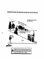
Slopes are a major factor related to loss-ofcontrol and tipover accidents, which can result in severe injury or death. All slopes
require extra caution. If you cannot back up
the slope or if you feel uneasy on it, do not
mow it.
DO:
• Mow up and down slopes, not across.
• Remove obstacles such as rocks, tree
limbs, etc.
• Watch for holes, ruts, or bumps. Uneven
terrain could overturn the machine. Tall
grass can hide obstacles.
• Use slow speed. Choose a low gear so
that you will not have to stop or shift
while on the slope.
• Follow the manufacturer's
recommendations for wheel weights or counterweights to improve stability.
• Use extra care with grass catchers or
other attachments.
These can change
the stability of the machine.
• Keep all movement on the slopes slow
and gradual
Do not make sudden
changes in speed or direction.
• Avoid starting or stopping on a slope. If
tires lose traction,
disengage the blades
and proceed slowly straight down the
slope.
DO NOT:
• Do not turn on slopes unless necessary,
and then, tum slowly and gradually
downhill, if possible.
• Do not mow near drop-offs, ditches, or
embankments.
The mower could
suddenly turn over if a wheel is over the
edge of a cliff or ditch, or if an edge
caves in.
• Do not
traction
• Do not
putting
• Do not
slopes.
3
mow on wet grass. Reduced
could cause sliding.
try to stabilize the machine by
your foot on the ground.
use grass catcher on steep
III. CHILDREN
Tragic accidents can occur if the operator
is not alert to the presence of children.
Children are often attracted to the
machine and the mowing activity.
Never
assume that children will remain where
you last saw them.
• Keep children out of the mowing area
and under the watchful care of another
responsible
adult.
• Be alert and turn machine off if children
enter the area.
• Before and when backing, look behind
and down for small children.
• Never carry children.
They may fall off
and be seriously injured or interfere
with safe machine operation.
• Never allow children to operate the
machine.
• Use extra care when approaching
blind
corners, shrubs, trees, or other objects
that may obscure vision.
•
•
•
•
•
IV. SERVICE
• Use extra care in handling gasoline
and other fuels. They are flammable
and vapors are explosive.
-Use only an approved container.
-Never remove gas cap or add fuel
with the engine running. Allow
engine to cool before refueling. Do
not smoke.
-Never refuel the machine indoors.
- Never store the machine or fuel
container inside where there is an
open flame, such as a water heater.
• Be sure the area is clear of other
people before mowing. Stop machine if
anyone enters the area.
• Never carry passengers
or children
even with the blades off.
• Do not mow in reverse unless absolutely necessary. Always look down
and behind before and while backing.
• Never carry children. They may fall off
and be seriously injured or interfere
with safe machine operation.
• Keep children out of the mowing area
and under the watchful care of another
responsible
adult.
4
•
•
Never run a machine inside a closed
area.
Keep nuts and bolts, especially blade
attachment bolts, tight and keep
equipment in good condition.
Never tamper with safety devices.
Check their proper operation regularly.
Keep machine free of grass, leaves, or
other debris build-up. Clean oil or fuel
spillage. Allow machine to cool before
storing.
Stop and inspect the equipment if you
strike an object. Repair, if necessary,
before restarting.
Never make adjustments
or repairs
with the engine running.
Grass catcher components
are subject
to wear, damage, and deterioration,
which could expose moving parts or
allow objects to be thrown. Frequently
check components
and replace with
manufacturer's
recommended
parts,
when necessary.
Mower blades are sharp and can cut.
Wrap the blade(s) or wear gloves, and
use extra caution when servicing them.
Check brake operation frequently.
Adjust and service as required.
• Be alert and turn machine
enter the area.
off if children
• Before and when backing, look behind
and down for small children.
• Mow up and down slopes (15 ° Max),
not across.
• Remove obstacles such as rocks, tree
limbs, etc.
• Watch for holes, ruts, or bumps.
Uneven terrain could overturn the
machine. Tall grass can hide obstacles.
• Use slow speed. Choose a low gear so
that you will not have to stop or shift
while on the slope.
• Avoid starting or stopping on a slope. If
tires lose traction, disengage the
blades and proceed slowly straight
down the slope.
• If machine stops while going uphill,
disengage blades, shift into reverse
and back down slowly.
• Do not turn on slopes unless necessary, and then, turn slowly and gradually downhill, if possible.
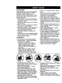
CAUTION:
Tow only the attachments
that are recommended
by and comply
with specifications
of the manufacturer
of
your tractor. Use common sense when
towing. Operate only at the lowest
possible speed when on a slope. Too
heavy of a load, while on a slope, is
dangerous.
"fires can lose traction with
the ground and cause you to lose control
of your tractor.
,_,WARNING:
Engine exhaust, some of
its constituents,
and certain vehicle
components
contain or emit chemicals
known to the State of California to cause
cancer and birth defects or other reproductive harm.
_kLook
for this symbol to point out
important safety precautions.
It means
CAUTION!!!
BECOMEALERT![!
YOUR
SAFETY IS INVOLVED.
,_WARNING:
Battery posts, terminals
and related accessories
contain lead and
lead compounds,
chemicals known to the
State of California to cause cancer and
birth defects or other reproductive harm.
Wash hands after handling.
,_, CAUTION:
In order to prevent
accidental starting when setting up,
transporting,
adjusting or making repairs,
always disconnect
spark plug wire and
place wire where it cannot contact spark
plug.
_, CAUTION:
Do not coast down a hill
in neutral, you may lose control of the
tractor.
5
PRODUCT
REPAIR AGREEMENT
SPECIFICATIONS
GASOLINE
CAPACITY
_,ND TYPE:
)IL TYPE
API-SF-SJ):
A Repair Agreement
is available on this
product. Contact your nearest Sears
store for details.
1.25 GALLONS
UNLEADED
REGULAR
CUSTOMER
SAE 10W30(above 32°F)
SAE 5W-30 (below 32°F)
OILCAPACITY:
W/FILTER:4.0
PINTS
W/OFILTER: 3.5 PINTS
SPARK PLUG:
CHAMPION
• Read and observe the safety rules.
• Follow a regular schedule in maintaining, caring for and using your tractor.
• Follow the instructions under "Maintenance" and "Storage" sections of this
owner's manual.
,_,WARNING:
This tractor is equipped
with an internal combustion
engine and
should not be used on or near any
unimproved
forest-covered,
brushcovered or grass-covered
land unless the
engine's exhaust system is equipped with
a spark arrester meeting applicable local
or state laws (if any). If a spark arrester is
used, it should be maintained
in effective
working order by the operator.
In the state of California the above is
RC12YC
GAP: .040")
GROUND
SPEED(MPH):
FORWARD:
REVERSE:
5.5
2.4
TIRE
FRONT:
REAR:
14 PSI
10 PSI
CHARGING
SYSTEM:
3AMPS BA-I-FERY
5 AMPS HEADLIGHT
BATTERY:
AMP/HR:
30
MIN. CCA:
240
CASE SIZE: U1R
BLADE BOLT
TORQUE:
27-35
RESPONSIBILITIES
required by law (Section 4442 of the
California Public Resources
Code).
Other states may have similar laws.
Federal laws apply on federal lands. A
spark arrester for the muffler is available
through your nearest Sears service
center (See REPAIR PARTS section of
this manual).
FT. LBS.
CONGRATULATIONS
on your purchase
of a new tractor. It has been designed,
engineered
and manufactured
to give
you the best possible dependability
and
performance.
Should you experience
any problem you
cannot easily remedy, please contact a
Sears or other qualified service center.
We have competent,
well-trained
technicians and the proper tools to service or
repair this tractor.
Please read and retain this manual. The
instructions will enable you to assemble
and maintain your tractor properly.
Always observe the "SAFETY RULES".
6
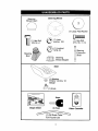
Steering Wheel
Steering
Wheel Insert
\
(1) Large Flat Washer
\\
(1) Hex Bolt
(1) Lock 3/8
washer
(1) Hex Bolt
5/16-18 x 1-1/4
3/8-16 x 1
(1) Locknut
5/16-18
Steering
t
Boot
_
Extension
Shaft
Steering
Steering Adapter
Wheel
Seat
(_Washer
17/32 x 1-3/16 x 12
Gauge
(_
_(1)
Knob
Keys
Slope Sheet
(2) Keys
For Future Use
7
F-1
Video Cassette
Your new tractor has been assembled at the factory with exception of those parts left
unassembled
for shipping purposes. To ensure safe and proper operation of your
tractor all parts and hardware you assemble must be tightened securely. Use the
correct tools as necessary to insure proper tightness. Review the video cassette before
you begin.
TOOLS
REQUIRED
FOR ASSEMBLY
_
easier. Standard wrench sizes you need
are listed below.
(1) 9/16" wrench
(2) 1/2" wrench
(1) Tire pressure
(1) Utility knife
gauge
When right or left hand is mentioned in
this manual, it means, from your point of
view, when you are in the operating
position (seated behind the steering
wheel).
asher
f__
/Steering
Tabs
Adapter------_
CARTON
BEFORE REMOVING
FROM SKID
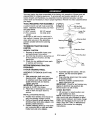
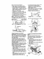
STEERING
ASSEMBLE
BOOT
_Extension
5/16 Locknut
,
'
'
Shaft
/ "'- '_
"4'-. ---_ "
"'-
Shaft
5116 Hex Bolt
Lower
TRACTOR
'
_' •
"
Tab
Slots
WHEEL
EXTENSION
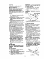
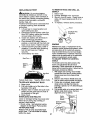
1. Slide extension
Boot
Steering Wheel_
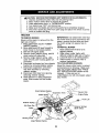
1. Remove all accessible loose parts
and parts boxes from carton.
2. Cut, from top to bottom, along lines on
all four corners of carton, and lay
panels flat.
3. Check for any additional loose parts
or cartons and remove.
ATTACH
Large Flat
_--_-_
TO REMOVE TRACTOR FROM
CARTON
UNPACK
_/./Insert
SHAFT
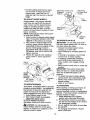
6. Assemble large flat washer, 3/8 lock
washer, 3/8 hex bolt and tighten
securely.
7. Snap steering wheel insert into center
of steering wheel.
8. Remove protective materials from
tractor hood and grill.
IMPORTANT:
Check for and remove any
staples in skid that may puncture tire
where tractor is to roll off skid.
AND
shaft onto lower
steering shaft. Align mounting holes
in extension and lower shafts and
install 5/16 hex bolt and Iocknut.
Tighten securely.
IMPORTANT: "Hghten bolt and nut
securely to 18-22 ft. Ibs torque.
2. Place tabs of steering boot over tab
slots in dash and push down to
secure.
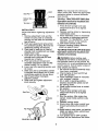
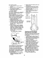
CHECK
BATTERY
1. Lift seat pan to raised position and
open battery box door.
NOTE: If this battery is put into service
after month and year indicated on label
(label located between terminals) charge
battery for minimum 01 one hour at 6-10
amps. (See "BATTERY" in Maintenance
section of this manual for charging
instructions).
INSTALL STEERING WHEEL
3. Position front wheels of the tractor so
they are pointing straight forward.
4. Remove steering wheel adapter from
steering wheel and slide adapter onto
steering shaft extension.
5. Position steering wheel so cross bars
are horizontal (left to right) and slide
inside boot and onto adapter.
8
NOTE: You may now roll or drive your
tractor off the skid. Follow the appropriate
instruction below to remove the tractor
from the skid.
Terminal
Battery
Door
TO ROLL
Te
INSTALL
TRACTOR
OFF SKID
Operation section for location
function
of controls)
(See
and
1. Press lift lever plunger and raise
attachment lift lever to its highest
position.
2. Release parking brake by depressing
clutch/brake pedal.
3. Place freewheel control in freewheeling position to disengage transmission (See "TO TRANSPORT"
in the
Operation section of this manual).
4. Roll tractor forward off skid.
5. Remove banding holding deflector
shield up against tractor.
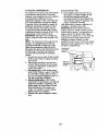
SEAT
Adjust seat before tightening adjustment
knob.
1. Remove adjustment
knob and flat
washer securing seat to cardboard
packing and set aside for assembly of
seat to tractor.
2. Pivot seat upward and remove from
the cardboard packing. Remove the
cardboard packing and discard.
3. Place seat on seat pan so head of
shoulder bolt is positioned over large
slotted hole in pan.
4. Push down on seat to engage
shoulder bolt in slot and pull seat
towards rear of tractor.
5. Pivot seat and pan forward and
assemble adjustment
knob and flat
washer loosely. Do not tighten.
6. Lower seat into operating position and
sit in seat.
7. Slide seat until a comfortable
position
is reached which allows you to press
clutch/brake
pedal all the way down.
8. Get off seat without moving its
adjusted position.
9. Raise seat and tighten adjustment
knob securely.
TO DRIVE
Operation
function
TRACTOR
OFF SKID (See
section for location
and
of
controls)
,_ WARNING:
Before starting, read,
understand and follow all instructions in
the Operation section of this manual. Be
sure tractor is in a well-ventilated
area. Be
sure the area in front of tractor is clear of
other people and objects.
1. Be sure all the above assembly steps
have been completed.
2. Check engine oil level and fill fuel
tank with gasoline.
3. Place freewheel control in "transmission engaged" position.
4. Sit on seat in operating position,
depress clutch/brake pedal and set
the parking brake.
5. Place motion control lever in neutral
(N) position.
6. Press lift lever plunger and raise
attachment lift lever to its highest
position.
7. Start the engine. After engine has
started, move throttle control to idle
position.
8. Release parking brake.
9. Slowly move the motion control lever
forward and slowly drive tractor off
skid.
10.Apply brake to stop tractor, set parking
brake and place motion control lever
in neutral position.
11 .Turn ignition key to "OFF" position.
Continue with the instructions that follow.
Seat
Bolt
Flat Washer _
dja tment
oob
9
INSTALL MULCHER PLATE
CHECK BRAKE SYSTEM
After you learn how to operate your
tractor, check to see that the brake is
properly adjusted. See "TO ADJUST
BRAKE" in the Service and Adjustments
section of this manual.
(If previously
removed)
1. Raise and hold deflector shield in
upright position.
2. Place front of mulcher plate over front
of mower deck opening and slide into
place, as shown.
3. Hook front latch into hole on front of
mower deck.
4. Hook rear latch into hole on back of
mower deck.
_CHECKLIST
Before you operate your new tractor, we
wish to assure that you receive the best
performance
and satisfaction from this
Quality Product.
Please review the following checklist:
•/All assembly instructions have been
completed.
,/No remaining loose parts in carton.
"/Battery
is properly prepared and
charged.
(Minimum 1 hour at 6 amps).
,/Seat is adjusted comfortably
and
tightened
securely.
"/All tires are properly inflated. (For
shipping purposes, the tires were
overinflated at the factory).
"/Be sure mower deck is properly leveled
side-to-side/front-to-rear
for best cutting
results. (Tires must be properly inflated
for leveling).
,/Check mower and ddve belts. Be sure
they are routed properly around pulleys
and inside all belt keepers.
,/Check wiring. See that all connections
are still secure and wires are properly
clamped.
,/Before
driving tractor, be sure freewheel control is in drive position.
While learning how to use your tractor,
pay extra attention to the following
important items:
,/Engine
oil is at proper level.
,/Fuel tank is filled with fresh, clean,
regular unleaded gasoline.
,/Become
familiar with all controls - their
A
_Hi, CAUTION:
Do not remove deflector
shield from mower. Raise and hold shield
when attaching mulcher plate and allow it
to rest on plate while in operation.
_-
Mulcher
Plate
Shield
Latch
Hooks
TO CONVERT
DISCHARGING
TO BAGGING
OR
Simply remove mulcher plate and store in
a safe place. Your mower is now ready for
discharging or installation of optional
grass catcher accessory.
NOTE: It is not necessary to change
blades. The mulcher blades are designed for discharging
and bagging also.
CHECK
TIRE
PRESSURE
The tires on your tractor were overinflated
at the factory for shipping purposes.
Correct tire pressure is important for best
cutting performance.
• Reduce tire pressure to PSI shown in
"PRODUCT SPECIFICATIONS"
section
of this manual.
CHECK
DECK
location and function.
Operate them
before you start the engine.
,/Be sure brake system is in safe
operating
condition.
,/It is important to purge the transmission
before operating your tractor for the first
time. Follow proper starting and
transmission
purging instructions (See
"TO START ENGINE" and "PURGE
TRANSMISSION"
in the Operation
section of this manual).
LEVELNESS
For best cutting results, mower housing
should be properly leveled. See "TO
LEVEL MOWER HOUSING" in the
Service and Adjustments
section of this
manual.
CHECK
FOR
ALL BELTS
PROPER
POSITION
OF
See the figures that are shown for
replacing motion and mower blade drive
belts in the Service and Adjustments
section of this manual. Verify that the
belts are routed correctly.
10
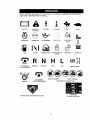
Thesesymbolsmay appearon yourtractoror in literaturesuppliedwith the product.
Learn and understandtheir meaning.
BATFERY
CAUTION OR
WARNING
REVERSE
ENGINE ON
ENGINE OFF
OIL PRESSURE
LIGHTS ON
FUEL
CHOKE
MOWER HEIGHT
PARKING BRAKE
LOCKED
r 'l
A'i-rACHMENT
CLUTCH ENGAGED
@_(_
IGNITION
R N
REVERSE
NEUTRAL
AI-I'ACHMENT
FORWARD
FAST
°vl,_._=P _[
H
L
HIGH
LOW
KEEP AREA CLEAR
CLUTCH DISENGAGED
SLOW
UNLOCKED
MOWER LIFT
®SI
PARKING BRAKE
SLOPE HAZARDS
(SEE SAFETY RULES SECTION)
FREE WHEEL
DANGER, KEEP HANDS AND FEET AWAY
(Automatic Models only)
11
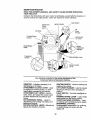
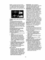
KNOW YOUR TRACTOR
READ THIS OWNER'S
YOUR TRACTOR
MANUAL
AND SAFETY
RULES
BEFORE
OPERATING
Compare the illustrations with your tractor to familiarize yourself with the locations of
various controls and adjustments.
Save this manual for future reference.
Attachment
Clutch
Light Switch
Ignition Switch
Lift
Ammeter Lever
_
Throttle/Choke
Control
Lever
Plunger
Attachment
Lift Lever
Clutch/Brake
Pedal
Height
Adjustment
Indicator
Freewheel
Control
Parking Brake Lever
Motion Control
Lever
Our tractors conform to the safety standards of the
American National Standards Institute,
AMMETER
- Indicates charging (+) or
discharging (-) of battery.
ATrACHMENT
CLUTCH LEVER - Used
to engage the mower blades, or other
attachments
mounted to your tractor.
ATTACHMENT
LIFT LEVER - Used to
raise, lower, and adjust the mower deck
or other attachments mounted to your
tractor.
CLUTCH/BRAKE
PEDAL - Used for
declutching and braking the tractor and
starting the engine.
MOTION CONTROL
LEVER - Selects the
speed and direction of tractor.
IGNITION SWITCH - Used for starting and
stopping the engine.
LIFT LEVER PLUNGER - Used to release
attachment lift lever when changing its
position.
LIGHT SWITCH - Turns the headlights on
and off,
PARKING BRAKE LEVER - Locks clutch/
brake pedal into the brake position.
THROTTLE/CHOKE
CONTROLUsed
for starting and controlling engine speed.
FREEWHEEL
CONTROL Disengagages transmission for pushing
or slowly towing the tractor with the
engine off.
12
The operation of any tractor can result in foreign objects thrown into the
eyes, which can result in severe eye damage.
Always wear safety
glasses or eye shields while operating your tractor or performing any
adjustments or repairs• We recommend
a wide vision safety mask over
spectacles or standard safety glasses.
• Never use choke to stop engine.
IMPORTANT:
Leaving the ignition switch
in any position other than "OFF" will
cause the battery to be discharged,
(dead).
NOTE:
Under certain conditions when
HOW TO USE YOUR TRACTOR
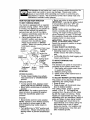
TO SET PARKING
BRAKE
Your tractor is equipped with an operator
presence sensing switch. When engine
is running, any attempt by the operator to
leave the seat without first setting the
parking brake will shut off the engine.
1. Depress clutch/brake
pedal into full
"BRAKE" position and hold.
2. Place parking brake lever in "ENGAGED" position and release
pressure from clutch/brake
pedal.
Pedal should remain in "BRAKE"
position.
Make sure parking brake will
hold tractor secure.
Throttle/
Attachment Clutch Lever
Choke.
"Engaged"
Control \
• Position
tractor is standing idle with the engine
running, hot engine exhaust gases may
cause "browning" of grass. To eliminate
this possibility, always stop engine when
stopping tractor on grass areas.
_CeAIUTION.: Alway,s s.top tra.ctor corny, as aescnDea aDove, eetore
leaving the operator's position; to empty
grass catcher, etc.
TO USE THROTTLE CONTROL
Always operate engine at full throttle.
• Operating engine at less than full
throttle reduces the battery charging
rate.
• Full throttle offers the best bagging and
mower performance.
, Ignition Key
"Disengaged"
Clutch/
Brake Pedal
Brake
"Engaged"
Position
=Brake"
Position
Position
TO MOVE
BLADES
The direction and speed of movement is
controlled by the motion control lever.
1. Start tractor with motion control lever
in neutral (N) position.
2. Release parking brake.
3. Slowly move motion control lever to
desired position.
Motion Control
Lever
-
• To stop mower blades,move
attachment clutch lever to "DISENGAGED"
position.
GROUND
TO ADJUST
DRIVE -
-
• Move throttle control to slow position.
NOTE: Failure to move throttle control to
slow position to allow engine to idle
before stopping may cause engine to
"backfire".
• Turn ignition key to "OFF" position and
remove key. Always remove key when
leaving tractor to prevent unauthorized
use.
MOWER
CU'I-rlNG
HEIGHT
The position of the attachment lift lever
determines the cutting height.
• Grasp lift lever.
• Press plunger with thumb and move
lever to desired position.
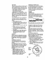
The cutting height range is approximately 1-1/2 to 4". The heights are
measured from the ground to the blade
tip with the engine not running. These
heights are approximate and may vary
depending upon soil conditions, height of
grass and types of grass being mowed.
• The average lawn should be cut to
approximately 2-1/2 inches during the
cool season and to over 3 inches
during hot months. For healthier and
better looking lawns, mow often and
after moderate growth.
• To stop ground drive, depress clutch/
brake pedal into full "BRAKE" position.
• Move motion control lever to neutral (N)
position.
IMPORTANT: The motion control lever
does not return to neutral (N) position
when the clutch/brake
pedal is depressed.
ENGINE
AND
BACKWARD
STOPPING
MOWER
FORWARD
13
• For best cutting performance,
grass
over 6 inches in height should be
mowed twice. Make the first cut
relatively high; the second to desired
height.
TO ADJUST
GAUGE
Position _;
Attachment
Lift Lever High
"'_'"
3/8-16
Locknut
\
Gauge
Wheel
Mounting
Bracket
3/8
/
j_i'_?sition
WHEELS
Gauge wheels
are properly adjusted
when they are slightly off the ground
when mower is at the desired cutting
height in operating position. Gauge
wheels then keep the deck in proper
position to help prevent scalping in most
terrain conditions.
NOTE: Adjust gauge wheels with tractor
on a flat level surface.
1. Adjust mower to desired cutting height
(See "TO ADJUST MOWER CUTTING
HEIGHT" in this section of manual).
2. With mower in desired height of cut
position, gauge wheels should be
assembled so they are slightly off the
ground. Install gauge wheel in
appropriate
hole with shoulder bolt,
3/8 washer, and 3/8-16 Iocknut and
tighten securely.
3. Repeat for opposite side installing
gauge wheel in same adjustment
hole.
Shoulder
Gauge Wheel
TO OPERATE
Attachment Clutch Lever
"Engaged" _
MOWER
Your tractor is equipped with an operator
presence sensing switch. Any attempt by
the operator to leave the seat with the
engine running and the attachment
clutch engaged will shut off the engine.
1. Select desired height of cut.
2. Start mower blades by engaging
attachment clutch control.
TO STOP MOWER BLADES disengage attachment clutch control.
CAUTION:
Do not operate the
mower without either the entire grass
catcher, on mowers so equipped, or the
deflector shield in place.
LoWtion
"oiseng ged --.
Position
_\_
" _
_)'_
"
D_eflector
Shield
TO OPERATE
ON HILLS
_I_CAUTION:
Do not drive up or down
hills with slopes greater than 15 ° and do
not drive across any slope.
• Choose the slowest speed before
starting up or down hills.
• Avoid stopping or changing speed on
hills.
• If slowing is necessary, move throttle
control lever to slower position.
• If stopping is absolutely necessary,
push clutch/brake
pedal quickly to
brake position and engage parking
brake.
• Move motion control lever to neutral (N)
position.
IMPORTANT: The motion control lever
does not return to neutral (N) position
when the clutch/brake pedal is depressed.
• To restart movement, slowly release
parking brake and clutch/brake
pedal.
• Slowly move motion control lever to
slowest setting.
• Make all turns slowly.
TO TRANSPORT
When pushing or towing your tractor, be
sure to disengage transmission by
placing freewheel control in freewheeling
position.
Free wheel control is located at
the rear drawbar of tractor.
1. Raise attachment lift to highest
position with attachment lift control.
2. Pull freewheel control out and down
into the slot and release so it is held in
the disengaged
position.
• Do not push or tow tractor at more than
two (2) MPH.
• To reengage transmission,
reverse
above procedure.
14
NOTE: To protect hood from damage
when transporting your tractor on a truck
or a trailer, be sure hood is closed and
secured to tractor. Use an appropriate
means of tying hood to tractor (rope, cord,
etc.).
TOWING
MENTS
CARTS
AND OTHER
IMPORTANT:
When operating in
temperatures
below 32°F(0°C), use fresh,
clean winter grade gasoline to help
insure good cold weather starting.
_kWARNING:
Experience indicates that
alcohol blended fuels (called gasohol or
using ethanol or methanol) can attract
moisture which leads to separation and
formation of acids during storage. Acidic
gas can damage the fuel system of an
engine while in storage.
To avoid engine
problems, the fuel system should be
emptied before storage of 30 days or
longer. Drain the gas tank, start the
engine and let it run until the fuel lines
and carburetor are empty. Use fresh fuel
next season. See Storage Instructions for
additional information.
Never use engine
or carburetor cleaner products in the fuel
tank or permanent damage may occur.
_CAUTION:
Fill to bottom of gas tank
filler neck. Do not overfill. Wipe off any
spilled oil or fuel. Do not store, spill or
use gasoline near an open flame.
ATTACH-
Tow only the attachments
that are
recommended by and comply with
specifications of the manufacturer of your
tractor. Use common sense when towing.
Too heavy of a load, while on a slope, is
dangerous. "fires can lose traction with
the ground and cause you to lose control
of your tractor.
BEFORE STARTING
CHECK
TO START ENGINE
When starting the engine for the first time
or if the engine has run out of fuel, it will
take extra cranking time to move fuel from
the tank to the engine.
1. Be sure freewheel control is in the
transmission
engaged position.
2. Sit on seat in operating position,
depress clutch/brake
pedal and set
parking brake.
3. Place motion control lever in neutral
THE ENGINE
ENGINE OIL LEVEL
The engine in your tractor has been
shipped, from the factory, already filled
with summer weight oil.
1. Check engine oil with tractor on level
ground.
2. Unthread and remove oil fill cap/
dipstick; wipe oil off. Reinsert the
dipstick into the tube and rest oil fill
cap on the tube. Do not thread the
cap onto the tube. Remove and read
oil level. If necessary, add oil until
"FULL" mark on dipstick is reached.
Do not overfill.
4.
(N) position.
Move attachment
clutch to "DISEN-
GAGED" position.
5. Move throttle control to choke position.
NOTE: Before starting, read the warm
and cold starting procedures below.
6. Insert key into ignition and turn key
clockwise to "START" position and
release key as soon as engine starts.
Do not run starter continuously
for
more than fifteen seconds per minute.
If the engine does not start after
several attempts, move throttle control
to fast position, wait a few minutes and
try again. If engine still does not start,
move the throttle control back to the
choke position and retry.
• For cold weather operation you should
change oil for easier starting (See "OIL
VISCOSITY CHART" in the Maintenance section of this manual).
• To change engine oil, see the Maintenance section in this manual.
ADD GASOLINE
• Fill fuel tank. Use fresh, clean, regular
unleaded gasoline with a minimum of
87 octane. (Use of leaded gasoline
will increase carbon and lead oxide
deposits and reduce valve life). Do not
mix oil with gasoline. Purchase fuel in
quantities that can be used within 30
days to assure fuel freshness.
15
WARM WEATHER
above)
STARTING
(50 ° F and
IMPORTANT:
Should your transmission
require removal for service or replacement, it should be purged after reinstallation before operating the tractor.
1. Place tractor safely on level surface
with engine off and parking brake set.
2. Disengage transmission by placing
freewheel
control in freewheeling
position (See "TO TRANSPORT"
in
this section of manual).
3. Sitting in the tractor seat, start engine.
After the engine is running, move
throttle control to slow position. With
motion control lever in neutral (N)
position, slowly disengage clutch/
brake pedal.
4. Move motion control lever to full
forward position and hold for five (5)
seconds. Move lever to full reverse
position and hold for five (5) seconds.
Repeat this procedure three (3) times.
NOTE: During this procedure there will be
no movement of drive wheels. The air is
being removed from hydraulic drive
system.
5. Move motion control lever to neutral
(N) position. Shut- off engine and set
parking brake.
6. Engage transmission
by placing
freewheel control in driving position
(See 'qO TRANSPORT"
in this section
of manual).
7. Sitting in the tractor seat, start engine.
After the engine is running, move
throttle control to half (1/2) speed. With
motion control lever in neutral (N)
position, slowly disengage clutch/
brake pedal.
8. Slowly move motion control lever
forward, after the tractor moves
approximately
five (5) feet, slowly
move motion control lever to reverse
position. After the tractor moves
approximately
five (5) feet return the
motion control lever to the neutral (N)
position. Repeat this procedure with
the motion control lever three (3)
times.
7. When engine starts, move the throttle
control to the fast position.
•
The attachments
and ground drive
can now be used. If the engine does
not accept the load, restart the engine
and allow it to warm up for one minute
using the choke as described above.
COLD WEATHER
STARTING
( 50 ° F and
below)
8.
When engine starts, allow engine to
run with the throttle control in the
choke position until the engine runs
roughly, then move throttle control to
fast position. This may require an
engine warm-up period from several
seconds to several minutes, depending on the temperature.
AUTOMATIC
TRANSMISSION
WARM UP
Before driving the unit in cold weather,
the transmission
should be warmed up as
follows:
1. Be sure the tractor is on level ground.
2. Place the motion control lever in
neutral. Release the parking brake
and let the clutch/brake
slowly return
to operating position.
3. Allow one minute for transmission
to
warm up. This can be done during
the engine warm up period.
• The attachments
can also be used
during the engine warm-up period after
the transmission
has been warmed up.
NOTE: If at a high altitude (above 3000
feet) or in cold temperatures
(below 32 F)
the carburetor fuel mixture may need to
be adjusted for best engine performance.
See "TO ADJUST CARBURETOR"
in the
Service and Adjustments
section of this
manual.
PURGE
TRANSMISSION
_CAUTION:
Never engage or disengage freewheel lever while the engine is
running.
To ensure proper operation and performance, it is recommended that the
transmission be purged before operating
tractor for the first time. This procedure will
remove any trapped air inside the
transmission which may have developed
during shipping of your tractor.
Your tractor is now purged and now ready
for normal operation.
16
MOWING
MULCHING
TIPS
MOWING TIPS
IMPORTANT:
For best performance,
keep mower housing free of built-up
grass and trash. Clean after each use.
• The special mulching blade will recut
the grass clippings many times and
reduce them in size so that as they fall
onto the lawn they will disperse into the
grass and not be noticed. Also, the
mulched grass will biodegrade
quickly
to provide nutrients for the lawn.
Always mulch with your highest engine
(blade) speed as this will provide the
best recutting action of the blades.
• Avoid cutting your lawn when it is wet.
Wet grass tends to form clumps and
interferes with the mulching action.
The best time to mow your lawn is the
early afternoon.
At this time the grass
has dried and the newly cut area will
not be exposed to the direct sun.
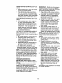
• For best results, adjust the mower
cutting height so that the mower cuts oft
only the top one-third of the grass
blades. For extremely heavy grass,
reduce your width of cut on each pass
and mow slowly.
• Mower should be properly leveled for
best mowing performance.
See "TO
LEVEL MOWER HOUSING" in the
Service and Adjustments section of this
manual.
• The left hand side of mower should be
used for trimming.
• Drive so that clippings are discharged
onto the area that has already been
cut. Have the cut area to the right of the
tractor. This will result in a more even
distribution of clippings and more
uniform cutting.
• When mowing large areas, start by
turning to the right so that clippings will
discharge away from shrubs, fences,
driveways, etc. After one or two
rounds, mow in the opposite direction
making left hand turns until finished.
1
Max 1/3
• If grass is extremely tall, it should be
mowed twice to reduce load and
possible fire hazard from dried clippings. Make first cut relatively high; the
second to the desired height.
• Do not mow grass when it is wet. Wet
grass will plug mower and leave
undesirable clumps.
Allow grass to dry
before mowing.
• Always operate engine at full throttle
when mowing to assure better mowing
performance
and proper discharge of
material.
Regulate ground speed by
selecting a low enough gear to give the
mower cutting performance
as well as
the quality of cut desired.
• When operating attachments,
select a
ground speed that will suit the terrain
and give best performance
of the
attachment being used.
• Certain types of grass and grass
conditions may require that an area be
mulched a second time to completely
hide the clippings. When doing a
second cut, mow across or perpendicular to the first cut path.
• Change your cutting pattern from week
to week. Mow north to south one week
then change to east to west the next
week. This will help prevent matting
and graining of the lawn.
17
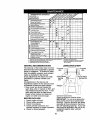
1 . Change more ofte_ whon operaUf_gunder a hoaw load or in high ambient tompeta_ms.
2 - Serv_e more often when operating In dirty or dusty _ndqtio_s.
3 ° If equipped wi_h Oilf_ter, change oil every 50 hours.
4 - Replace blades more o_en when mowing in sandy sod,
GENERAL
5 - If eqLdppedwilh 8djus_.13_ syslem.
6 - Not required if equipped with maintenance=free bakery,
7 _l_ht 6N f_t axle pivot bolt to 35 ft.'_bs, maximum,
DO not Overtighton.
LUBRICATION CHART
RECOMMENDATIONS
The warranty on this tractor does not cover
items that have been subjected to operator
abuse or negligence. To receive full value
from the warranty, operator must maintain
tractor as instructed in this manual.
(D Spindle -Zerk
Some adjustments will need to be made
periodically to propedy maintain your
tractor.
All adjustments in the Service and
Adjustments section of this manual should
be checked at least once each season.
• Once a year you should replace the
spark plug, clean or replace air filter, and
check blades and belts for wear. A new
spark plug and clean air filter assure
proper air-fuel mixture and help your
engine run better and last longer.
_Front Wheel
Bearing
Zerk
BEFORE
EACH
- (_ Spindle
Zerk
Bearing Zerk
@Engine
_General Purpose Grease
_)ReferTO Maintenance =ENGINE'Section
USE
IMPORTANT:
Do not oil or grease the
pivot points which have special nylon
bearings. Viscous lubricants will attract
dust and dirt that will shorten the life of
the self-lubricating bearings. If you feel
they must be lubricated, use only a dry,
powdered graphite type lubricant
sparingly.
1.
2.
3.
4.
Check engine oil level.
Check brake operation.
Check tire pressure.
Check operator presence and
interlock systems for proper operation.
5. Check for loose fasteners.
18
TRACTOR
Always observe safety rules when
performing
any maintenance.
BRAKE OPERATION
If tractor requires more than six (6) feet
stopping distance at high speed in
highest gear, then brake must be adjusted. (See "TO ADJUST BRAKE" in the
Service and Adjustments
section of this
manual).
TIRES
• Maintain proper air pressure in all tires
(See "PRODUCT SPECIFICATIONS"
section of this manual).
• Keep tires free of gasoline, oil, or insect
control chemicals which can harm
rubber.
• Avoid stumps, stones, deep ruts, sharp
objects and other hazards that may
cause tire damage.
NOTE: To seal tire punctures and prevent
flat tires due to slow leaks, tire sealant
may be purchased from your local parts
dealer. Tire sealant also prevents tire dry
rot and corrosion.
OPERATOR
PRESENCE SYSTEM
Be sure operator presence and interlock
systems are working properly. If your
tractor does not function as described,
repair the problem immediately.
• The engine should not start unless the
brake pedal is fully depressed and
attachement clutch control is in the
disengaged
position.
• When the engine is running, any
attempt by the operator to leave the
seat without first setting the parking
brake should shut off the engine.
• When the engine is running and the
attachment clutch is engaged, any
attempt by the operator to leave the
seat should shut off the engine.
• The attachment clutch should never
operate unless the operator is in the
seat.
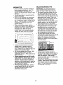
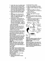
BLADE CARE
For best results mower blades must be
kept sharp.
blades.
BLADE
Replace
IMPORTANT:
To ensure proper assembly,
center hole in blade must align with star
on mandrel assembly.
4. Reassemble hex bolt, lock washer
and flat washer in exact order as
shown.
5. Tighten bolt securely (27-35 Ft. Lbs.
torque).
IMPORTANT:
Blade bolt is grade 8 heat
treated.
Trailing Edge Up
Mandrel / Assembly
"_,o. Blade
r i_i I
Center
Hole
Flat Washer _._
'J_
Lock Washer
"h-.'_
_'__
".,._ _,5
_q
_F._,
_
"Star
&-_--Hex Bolt (Grade
*A Grade 8 heat treated bolt can be identified
by six lines on the bolt head.
TO SHARPEN
BLADE
NOTE: We do not recommend sharpening blade - but if you do, be sure the
blade is balanced.
Care should be taken to keep the blade
balanced.
An unbalanced blade will
cause excessive vibration and eventual
damage to mower and engine.
• The blade can be sharpened with a file
or on a grinding wheel. Do not attempt
to sharpen while on the mower.
• To check blade balance, you will need
a 5/8" diameter steel bolt, pin, or a cone
balancer.
(When using a cone balancer, follow the instructions supplied
with balancer.)
NOTE: Do not use a nail for balancing
blade. The lobes of the center hole may
appear to be centered, but are not.
• Slide blade on to an unthreaded
portion of the steel bolt or pin and hold
the bolt or pin parallel with the ground.
If blade is balanced, it should remain in
a horizontal position.
If either end of
the blade moves downward, sharpen
the heavy end until the blade is
balanced.
bent or damaged
REMOVAL
1. Raise mower to highest position to
allow access to blades.
2. Remove hex bolt, lock washer and flat
washer securing blade.
3. Install new or resharpened
blade with
trailing edge up towards deck as
shown.
518"
e
Center Hole
19
BATTERY
TRANSAXLE
Your tractor has a battery charging system
which is sufficient for normal use. However, periodic charging of the battery with
an automotive
charger will extend its life.
• Keep battery and terminals clean.
• Keep battery bolts tight.
• Keep small vent holes open.
• Recharge at 6-10 amperes for 1 hour.
NOTE: The original equipment battery on
your tractor is maintenance
free. Do not
attempt to open or remove caps or covers.
Adding or checking level of electrolyte is
not necessary.
The transaxle was sealed at the factory
and fluid maintenance is not required for
the life of the transaxle. Should the
transaxle ever leak or require servicing,
contact your nearest authorized service
center/department.
TO CLEAN
BATTERY
AND TERMINALS
Corrosion and dirt on the battery and
terminals can cause the battery to "leak"
power.
1. Open battery box door.
2. Disconnect BLACK battery cable first
then RED battery cable and remove
battery from tractor.
3. Rinse the battery with plain water and
dry.
4. Clean terminals and battery cable
ends with wire brush until bright.
5. Coat terminals with grease or petroleum jelly.
6. ReinstaU battery (See "REPLACING
BATTERY" in the SERVICE AND
ADJUSTMENTS
section of this
manual).
V-BELTS
Check V-belts for deterioration and wear
after 100 hours of operation and replace
if necessary. The belts are not adjustable.
Replace belts if they begin to slip from
wear.
TRANSAXLE
COOLING
The transmission
fan and cooling fins
should be kept clean to assure proper
cooling.
Do not attempt to clean fan or transmission while engine is running or while the
transmission is hot. To prevent possible
damage to seals, do not use high
pressure water or steam to clean
transaxle.
• Inspect cooling fan to be sure fan
blades are intact and clean.
• Inspect cooling fins for dirt, grass
clippings and other materials.
To
prevent damage to seals, do not use
compressed air or high pressure
sprayer to clean cooling fins.
PUMP FLUID
ENGINE
LUBRICATION
Only use high quality detergent oil rated
with API service classification SF-SJ.
Select the oil's SAE viscosity grade
according to your expected operating
temperature.
SAE VISCOSITY GRADES
-20
30
32
40
6G
I0
TEMPERATURE
RANGE ANTICIPATED
80
/
i
BEFORE NEXT OIL CHANGE
Change the oil after every 50 hours of
operation or at least once a year if the
tractor is not used for 50 hours in one
year.
Check the crankcase oil level before
starting the engine and after each eight
(8) hours of operation.
Tighten oil fill cap/
dipstick securely each time you check the
oil level.
TO CHANGE
ENGINE
OIL
Determine temperature
range expected
before oil change. All oil must meet API
service classification
SF-SJ.
• Be sure tractor is on level surface.
• Oil will drain more freely when warm.
• Catch oil in a suitable container.
1. Remove oil fill cap/dipstick.
Be careful
not to allow dirt to enter the engine
when changing oil.
2. Remove yellow cap from end of drain
valve and install the drain tube onto
the fitting.
Oil Drain Valve
DrainTube
2O
TO SERVICE
3.
Unlock drain valve by pushing inward
slightly and turning counterclockwise.
4. To open, pull out on the drain valve.
5. After oil has drained completely, close
and lock the drain valve by pushing
inward and turning clockwise until the
pin is in the locked position as shown.
6. Remove the drain tube and replace
the cap onto to the end of the drain
valve.
3. Slide foam pre-cleaner off cartridge.
4. Wash it in liquid detergent and water.
5. Squeeze it dry in a clean cloth. Allow it
to dry.
6. Saturate it in engine oil. Wrap it in
clean, absorbent cloth and squeeze to
remove excess oil.
TO SERVICE
Refill engine with oil through oil fill
dipstick tube. Pour slowly. Do not
overfill. For approximate
capacity see
"PRODUCT SPECIFICATIONS"
section of this manual.
8. Use gauge on oil fill cap/dipstick
for
checking level. Insert dipstick into the
tube and rest the oil fill cap on the
tube. Do not thread the cap onto the
tube when taking reading.
Keep oil
at "FULL" line on dipstick. Tighten cap
onto the tube securely when finished.
CLEAN AIR SCREEN
Air Cleaner
Foam
Pre- \
Cleaner
Air screen must be kept free of dirt and
chaff to prevent engine damage from
overheating. Clean with a wire brush or
compressed air to remove dirt and
stubborn dried gum fibers.
AIR INTAKE/COOLING
CARTRIDGE
• Replace a dirty, bent, or damaged
cartridge.
NOTE: Do not wash the paper cartridge
or use pressurized air, as this will damage
the cartridge.
7. Reinstall the pre-cleaner
(cleaned and
oiled) over the paper cartridge.
8. Reassemble
air cleaner, wing nut,
cover and tighten knob securely.
7.
CLEAN
PRE-CLEANER
Knob
Nut
Rubber
Grommet
Paper
Cadridge
AREAS
\Air Cleaner
Base
To insure proper cooling, make sure the
grass screen, cooling fins, and other
external surfaces of the engine are kept
clean at all times.
Screen
Every 100 hours of operation (more often
under extremely dusty, dirty conditions),
remove the blower housing and other
cooling shrouds. Clean the cooling fins
and external surfaces as necessary.
Make sure the cooling shrouds are
reinstalled.
MUFFLER
Inspect and replace corroded muffler and
spark arrester (if equipped) as it could
create a fire hazard and/or damage,
SPARK PLUGS
NOTE:
Operating the engine with a
blocked grass screen, dirty or plugged
cooling fins, and/or cooling shrouds
removed will cause engine damage due
to overheating.
Replace spark plugs at the beginning of
each mowing season or after every 100
hours of operation, whichever occurs first.
Spark plug type and gap setting are
shown in "PRODUCT SPECIFICATIONS"
section of this manual.
AIR FILTER
Your engine will not run properly using a
dirty air filter. Clean the foam pre-cleaner
after every 25 hours of operation or every
season.
Service paper cartridge every
100 hours of operation or every season,
whichever occurs first.
Service air cleaner more often under
dusty conditions.
1. Remove knob and cover.
2. Remove wing nut and air cleaner
from base.
21
ENGINE OIL FILTER
IN-LINE
Replace the engine oil filter every season
or every other oil change if the tractor is
used more than 100 hours in one year.
1. Drain oil from engine crankcase (See
"TO CHANGE ENGINE OIL" in this
section of this manual, through step
remove drain plug).
2. Remove oil filter and wipe off filter
adapter.
3. Apply a thin coating of new engine oil
to the rubber gasket on replacement
oil filter.
4. Install replacement
oil filter on filter
adapter. Turn oil filter clockwise until
rubber gasket contacts the filter
adapter, then tighten filter an additional 1/2 turn.
The fuel filter should be replaced once
each season. If fuel filter becomes
clogged, obstructing fuel flow to carburetor, replacement
is required.
1. With engine cool, remove filter and
plug fuel line sections.
2. Place new fuel filter in position in fuel
line with arrow pointing towards
carburetor.
3. Be sure there are no fuel line leaks
and clamps are properly positioned.
4. Immediately wipe up any spilled
gasoline.
Fill crankcase with new oil (See "-I-O
CHANGE ENGINE OIL" in this section
of this manual). For approximate
capacity see "PRODUCT SPECIFICATIONS" section of this manual.
6. Start the engine and check for oil
leaks. Correct any leaks before
placing engine into full operation.
FUEL FILTER
5.
Fuel Filter
-
_
CLEANING
• Clean engine, battery, seat, finish, etc.
of all foreign matter.
• Keep finished surfaces and wheels free
of all gasoline, oil, etc.
• Protect painted surfaces with automotive type wax.
We do not recommend using a garden
hose to clean your tractor unless the
electrical system, muffler, air filter and
carburetor are covered to keep water out.
Water in engine can result in a shortened
engine life.
22
_CAUTION:
BEFORE PERFORMING
ANY SERVICE OR ADJUSTMENTS:
1. Depress clutch/brake
pedal fully and set parking brake.
2. Place motion control lever in neutral (N) position.
3. Place attachment clutch in "DISENGAGED"
position.
4. Turn ignition key "OFF" and remove key.
5. Make sure the blades and all moving parts have completely stopped.
6. Disconnect spark plug wire from spark plug and place wire where it cannot
come in contact with plug.
TRACTOR
IMPORTANT:
If an attachment other than
the mower deck is to be mounted on the
tractor, remove the front links and hook
the clutch spring Into square hole in
frame.
TO INSTALL MOWER
1. Raise attachment lift lever to its
TO REMOVE MOWER
Mower will be easier to remove from the
right side of tractor.
1. Place attachment clutch in "DISENGAGED" position.
2. Move attachment lift lever forward to
3.
4.
5.
6.
7.
8.
9.
lower mower to its lowest position.
Roll belt off engine pulley.
Remove small retainer spring, and lift
clutch spring off pulley bolt.
Remove large retainer spring, slide
collar off and push housing guide out
of bracket.
Disconnect anti-sway bar from chassis
bracket by removing retainer spring.
Disconnect suspension
arms from
rear deck brackets by removing
retainer springs.
Disconnect front links from deck by
removing retainer springs.
Raise lift lever to raise suspension
arms. Slide mower out from under
highest position.
2. Slide mower under tractor with
deflector shield to right side of tractor.
3. Lower lift lever to its lowest position.
4. Install mower in reverse order of
removal instructions.
TO LEVEL MOWER HOUSING
Adjust the mower while tractor is parked
on level ground or driveway.
Make sure
tires are properly inflated (See "PRODUCT SPECIFICATIONS"
section of this
manual).
If tires are over or
underinflated,
you will not properly adjust
your mower.
tractor.
Small Retainer Spring
Clutch
Link
Retainer
Anti-Sway
(Both Sides)
Housing Guide
Large Retainer Spring
23
SIDE-TO-SIDE
ADJUSTMENT
• Raise mower to its highest position.
• At the midpoint of both sides of mower,
measure height from bottom edge of
mower to ground.
Distance "A" on both
sides of mower should be the same or
within 1/4" of each other.
• If adjustment is necessary, make
adjustment on one side of mower only.
• To raise one side of mower, tighten rift
link adjustment nut on that side.
• To lower one side of mower, loosen lift
link adjustment nut on that side.
NOTE:
Each full turn of adjustment nut
will change mower height about 1/8".
• Recheck measurements
after adjusting.
Bottom Edge of
Mower to Ground
Both Front Links Should be Equal in Length
Bottom Edge of
Mower to Ground
\
_i
• To raise front of mower, loosen nut "F"
from trunnion on both front links.
Tighten nut "E" on both front links an
equal number of turns.
• When distance "D" is 1/8" to 1/2" lower
at front than rear, tighten nut "F" against
trunnion on both front links.
• Recheck side-to-side
adjustment.
/
Suspensi°n
Nut
ft Link
djustment
ut
FRONT-TO-BACK
ADJUSTMENT
IMPORTANT'
Deck must be level side-toside. If the following front-to-back
adjustment is necessary, be sure to adjust both
front links equally so mower will stay
level side-to-side.
To obtain the best cutting results, the
mower housing should be adjusted so
that the front is approximately 1/8" to 1/2"
lower than the rear when the mower is in
its highest position.
Check adjustment on right side of tractor.
Measure distance "D" directly in front and
behind the mandrel at bottom edge of
mower housing as shown.
• Before making any necessary adjustments, check that both front links are
equal in length.
• If links are not equal in length, adjust
one link to same length as other link.
• To lower front of mower loosen nut "E"
on both front links an equal number of
turns.
• When distance "D" is 1/8" to 1/2" lower
at front than rear, tighten nuts "F"
against trunnion on both front links.
Front
Links
TO REPLACE
BELT
- Nut "E"
Trunnion
MOWER
BLADE
DRIVE
The mower blade drive belt may be
replaced without tools. Park the tractor on
level surface. Engage parking brake.
BELT REMOVAL1. Remove mower from tractor (See "TO
REMOVE MOWER" in this section of
this manual).
2. Work belt off both mandrel pulleys and
idler pulleys.
3. Pull belt away from mower.
Mandrel
Pulley
24
BELT INSTALLATION
-
4.
Install new belt in reverse order of
removal.
5. Make sure belt is in all pulley grooves
and inside all belt guides.
6. Install mower in reverse order of
removal instructions.
TO ADJUST
Remove belt from stationary idler and
clutching idler.
3. Pull belt slack toward rear of tractor.
Carefully remove belt upwards from
transmission
input pulley and over
cooling fan blades.
.
Pull belt toward front of tractor and
remove downward from around
engine pulley.
5. Install new belt by reversing above
procedure.
.
BRAKE
Your tractor is equipped with an adjustable
brake system which is mounted on the
side of the transaxle.
If tractor requires more than six (6) feet
stopping distance at high speed in highest
gear on a level dry concrete or paved
surface, then brake must be adjusted.
1. Depress clutch/brake pedal and
engage parking brake.
2. Measure distance between brake
operating arm and nut "A" on brake rod.
3. If distance is other than 1-9/16", loosen
jam nut and turn nut "A" until distance
becomes 1-9/16". Retighten jam nut
against nut "A".
4. Road test tractor for proper stopping
distance as stated above. Readjust if
necessary.
If stopping distance is still
greater than six (6) feet in highest gear,
further maintenance
is necessary.
Contact a Sears or other qualified
service center.
Engine
Pulley
Clutching IdlerStationary Idler-.....
Transmission
Input Pulley
C
With Parking Brake "Engaged"
TRANSAXLE
MOTION CONTROL
LEVER NEUTRAL ADJUSTMENT
The motion control lever has been preset
at the factory and adjustment should not
be necessary.
1. Loosen adjustment bolt in front of the
right rear wheel, and lightly tighten.
2. Start engine and move motion control
lever until tractor does not move
forward or backward.
3. Hold motion control lever in that
Nut "A"
Jam Nut
position and turn engine off.
While holding motion control lever in
place, loosen the adjustment bolt.
5. Move motion control lever to the
neutral (N) (lock gate) position.
6. Tighten adjustment bolt securely.
NOTE:
If additional clearance is needed
to get to adjustment bolt, move mower
deck height to the lowest position.
After above adjustment is made, if the
tractor still creeps forward or backward
while motion control lever is in neutral
position, follow these steps:
1. Loosen the adjustment
bolt.
_erating
4.
_
Arm
Do Not touch this nut. If further brake adjustment is necessary contact your nearest
authorized service center/department
TO REPLACE
MOTION
DRIVE BELT
Park the tractor on level surface. Engage
parking brake. For assistance, there is a
belt installation guide decal on bottom
side of left footrest.
1. Remove mower (See "TO REMOVE
MOWER" in this section of this
manual.)
25
2. Move the motion control lever 1/4 to
1/2 inch in the direction it is trying to
creep.
3. Tighten adjustment
bolt securely.
4. Start engine and test.
5. If tractor still creeps, repeat above
steps until satisfied.
Motion Control
Neutral Lock Gate
Lever
Washers
Retaining
Axle
Cover
i
Square Key -------"-_(Rear Wheel Only)
TO START
BATTERY
WITH A WEAK
,_CAUTION:
Lead-acid batteries generate
explosive gases. Keep sparks, flame and
smoking materials away from batteries.
Always wear eye protection when around
batteries.
If your battery is too weak to start the engine, it
should be recharged. (See "BA'FI'ERY" in the
MAINTENANCE section of this manual).
If "jumper cables" are used for emergency
starting, follow this procedure:
IMPORTANT: Your tractor is equipped with a
12 volt negative grounded system. The other
vehicle must also be a 12 volt negative
grounded system. Do not use your tractor
battery to start other vehicles.
AdjL
TRANSMISSION
MENT
ENGINE
REMOVAL/REPLACE-
Should your transmission
require
removal for service or replacement, it
should be purged after reinstallation and
before operating the tractor. See
"PURGE TRANSMISSION"
in the
Operation section of this manual.
TO ADJUST STEERING WHEEL ALIGNMENT
If steering wheel crossbars are not
horizontal (left to right) when wheels are
positioned straight forward, remove
steering wheel and reassemble per
instructions in the Assembly section of
this manual.
FRONT WHEEL TOE-IN/CAMBER
TO AI3"ACH JUMPER CABLES 1. Connect each end of the RED cable to
the POSITIVE (+) terminal of each
battery, taking care not to short
against chassis.
2. Connect one end of the BLACK cable
The front wheel toe-in and camber are
not adjustable on your tractor. If damage
has occurred to affect the front wheel toein or camber, contact a Sears or other
qualified service center.
TO REMOVE WHEEL FOR REPAIRS
to the NEGATIVE (-) terminal of fully
charged battery.
3. Connect the other end of the BLACK
cable to good CHASSIS GROUND,
away from fuel tank and battery.
1. Block up axle securely.
2. Remove axle cover, retaining ring and
washers to allow wheel removal (rear
wheel contains a square key - Do not
lose).
3. Repair tire and reassemble.
NOTE: On rear wheels only: align
grooves in rear wheel hub and axle.
Insert square key.
4. Replace washers and snap retaining
ring securely in axle groove.
5. Replace axle cover.
NOTE: To seal tire punctures and prevent
flat tires due to slow leaks, tire sealant
may be purchased from your local parts
dealer. Tire sealant also prevents tire dry
rot and corrosion.
TO REMOVE CABLES, REVERSE ORDER o
1. BLACK cable first from chassis and
then from the fully charged battery.
2. RED cable last from both batteries.
Positive Terminal
Positive
26
Charged
Battery
Terminal
REPLACING
TO REMOVE HOOD AND GRILL ASSEMBLY
1. Raise hood.
2. Unsnap headlight wire connector.
3. Stand in front of tractor. Grasp hood at
sides, tilt toward engine and lift off of
tractor.
4. To replace, reverse above procedure.
BATTERY
,_CAUTION:
Do not short battery
terminals by allowing a wrench or any
other object to contact both terminals at
the same time. Before connecting battery,
remove metal bracelets, wristwatch
bands, rings, etc.
Positive terminal must be connected first
to prevent sparking from accidental
grounding.
1. Lift seat pan to raised position and
open battery box door.
2. Disconnect BLACK battery cable first
then RED battery cable and carefully
remove battery from tractor.
3. Install new battery with terminals in
same position as old battery.
4. First connect RED battery cable to
positive (+) terminal with hex bolt and
keps nut as shown. Tighten securely.
5. Connect BLACK grounding cable to
negative (-) terminal with remaining
hex bolt and keps nut. Tighten
securely.
6. Close battery box door.
Hood
\
Headlight Wire
Connector
ENGINE
Maintenance, repair, or replacement of the
emission control devices and systems, which
are being done at the customers expense,
may be performed by any non-road engine
repair establishment or individual. Warranty
repairs must be performed by an authorized
engine manufacturer's service outlet.
TO ADJUST THROTTLE CONTROL
CABLE
Seat
Positive (Red) Cable
The throttle control has been preset at the
factory and adjustment should not be
necessary. Check adjustment as described
below before loosening cable. If adjustment is
necessary, proceed as follows:
1. With engine not running, move throttle
control lever from slow to choke position.
Slowly move lever from choke to fast
position.
2. Check to see if hole in throttle lever and
hole in speed control bracket are aligned.
3. If holes are not aligned, loosen cable
clamp screw and align the holes by
inserting a pencil or a 1/4" drill bit through
beth holes.
4. Pull throttle cable up to remove slack and
tighten cable clamp screw. Remove
alignment pencil or drill bit.
Negative (Black) Cable
TO REPLACE HEADLIGHT
BULB
1. Raise hood.
2. Pull bulb holder out of the hole in the
backside of the grill.
3. Replace bulb in holder and push bulb
holder securely back into the hole in
the backside of the grill.
4. Close hood.
INTERLOCKS
AND RELAYS
Cable
Clamp______
Screw _
Loose or damaged wiring may cause your
tractor to run poorly, stop running, or
prevent it from starting,
• Check wiring. See electrical wiring
diagram in the Repair Parts section.
TO REPLACE FUSE
Replace with 20 amp automotive-type
plug-in fuse. The fuse holder is located
behind the dash.
i :,.--,-.
Speed Control
Bracket _
L
e.ev
27
TO ADJUST
CARBURETOR
The carburetor has been preset at the factory
and adjustment should not be necessary.
However, minor adjustment may be required
to compensate for differences in fuel,
temperature, altitude or load. If the carburetor
does need adjustment, proceed as follows:
In general, turning the adjusting needles in
(clockwise) decreases the supply of fuel to
the engine giving a leaner fuel/air mixture.
Turning the adjusting needles out (counterclockwise) increases the supply of fuel to the
engine giving a richer fuel/air mixture.
IMPORTANT: Damage to the needles and
seats in carburetor may result if turned in too
tight.
NOTE: The carburetor on this engine is low
emission. It is equipped with an idle fuel
adjusting needle with a limiter cap, which
allows some adjustment within the limits
allowed by the cap. Do not attempt to remove
the limiter cap. The limiter cap cannot be
removed without breaking the adjusting
needle.
1. Be sure you have a clean air filter and the
throttle control cable is adjusted propedy
(see above).
2. Start engine and allow to warm for five
minutes. Make adjustments with engine
running and shift/motion control lever in
neutral (N) position.
3. Idle seeed settina - With throttle control
lever in slow position, engine should idle
at 1750 RPM. If engine idles too slow or
fast, turn idle speed adjusting screw in or
out until correct idle is attained.
ACCELERATION TEST6. Move throttle control lever from slow to
fast position. If engine hesitates or dies,
turn idle fuel adjusting needle out
(counterclockwise) 1/8 tum. Repeat test
and continue to adjust, if necessary, until
engine accelerates smoothly.
High speed stop is factory adjusted. Do
not adjust - damage may result.
IMPORTANT:
Never tamper with the
engine governor, which is factory set for
proper engine speed. Overspeeding
the
engine above the factory high speed
setting can be dangerous. If you think the
engine-governed
high speed needs
adjusting, contact a Sears or other
qualified service center, which has proper
equipment and experience
to make any
necessary
adjustments.
Idle Speed
Adjusting
Idle Fuel
Adjusting_
Needle
4.
Idle fuel needle setting - With throttle
control lever in slow position, turn idle fuel
adjustment needle in (clockwise) until
engine begins to die and then turn out
(counterclockwise) until engine runs
rough. Turn needle to a point midway
between those two positions.
5. Recheck idle speed. Readjust if necessary.
28
Immediately prepare your tractor for
storage at the end of the season or if the
tractor will not be used for 30 days or
more.
,_
CAUTION:
Never store the tractor
with gasoline in the tank inside a building
where fumes may reach an open flame or
spark. Allow the engine to cool before
storing in any enclosure.
TRACTOR
Remove mower from tractor for winter
storage. When mower is to be stored for
a period of time, clean it thoroughly,
remove all dirt, grease, leaves, etc. Store
in a clean, dry area.
1. Clean entire tractor (See "CLEANING"
in the Maintenance section of this
manual).
2. Inspect and replace belts, if necessary
(See belt replacement
instructions
in
the Service and Adjustments
section
of this manual).
3. Lubricate as shown in the Maintenance section of this manual.
4. Be sure that all nuts, bolts and screws
are securely fastened.
Inspect moving
parts for damage, breakage and wear.
Replace if necessary.
5. Touch up all rusted or chipped paint
surfaces; sand lightly before painting.
Also, experiance
indicates that alcohol
blended fuels (called gasohol or using
ethanol or methanol) can attract moisture
which leads to separation and formation
of acids during storage. Acidic gas can
damage the fuel system of an engine
while in storage.
1. Drain the fuel tank.
2.
Start the engine and let it run until the
fuel lines and carburetor are empty.
• Never use engine or carburetor cleaner
products in the fuel tank or permanent
damage may occur.
• Use fresh fuel next season.
NOTE:
Fuel stabilizer is an acceptable
alternative in minimizing the formation of
fuel gum deposits during storage. Add
stabilizer to gasoline in fuel tank or
storage container.
Always follow the mix
ratio found on stabilizer container.
Run
engine at least 10 minutes after adding
stabilizer to allow the stabilizer to reach
the carburetor.
Do not drain the gas tank
and carburetor if using fuel stabilizer.
ENGINEOIL
Drain oil (with engine warm) and replace
with clean engine oil. (See "ENGINE" in
the Maintenance
section of this manual).
CYLINDER(S)
1. Remove spark plug(s).
2. Pour one ounce of oil through spark
plug hole(s) into cylinder(s).
3. Turn ignition key to "START" position
for a few seconds to distribute oil.
4. Replace with new spark plug(s).
BATrERY
• Fully charge the battery for storage.
• After a period of time in storage, battery
may require recharging.
• To help prevent corrosion and power
leakage during long periods of storage,
battery cables should be disconnected
and battery cleaned thoroughly
(see
"TO CLEAN BATIERY
AND TERMINALS" in the Maintenance
section of
this manual).
• After cleaning, leave cables disconnected and place cables where they
cannot come in contact with battery
terminals.
OTHER
• Do not store gasoline
to another.
from one season
• Replace your gasoline can if your can
starts to rust. Rust and/or dirt in your
gasoline will cause problems.
• If possible, store your tractor indoors
and cover it to give protection from dust
and dirt.
• Cover your tractor with a suitable
protective cover that does not retain
moisture.
Do not use plastic. Plastic
cannot breathe which allows conden-
• If battery is removed from tractor for
storage, do not store battery directly on
concrete or damp surfaces.
sation to form and will cause your
tractor to rust.
IMPORTANT:
Never cover tractor while
engine
and exhaust areas are still warm.
ENGINE
FUELSYSTEM
IMPORTANT:
It is important to prevent
gum deposits from forming in essential
fuel system parts such as carburetor, fuel
hose, or tank during storage.
29
TROUBLESHOOTING
CHART
PROBLEM
Will not start
CAUSE
CORRECTION
1, Out of fuel.
2. Engine not "CHOKED"
properly.
3. Engine flooded.
4. Bad spark plug.
5. Dirty air filter.
6. Dirty fuel filter.
7. Water in fuel.
8.
9.
Loose or damaged wiring.
Carburetor out of adjustment.
' 10.Engine valves
adjustment.
Hard to start
1.
2.
3.
4.
5.
out of
Dirty air filter.
Bad spark plug.
Weak or dead battery.
Dirty fuel filter.
Stale or dirty fuel.
6. Loose or damaged wiring.
7. Carburetor out of adjustment,
8.
Engine will not
turn over
Engine clicks but
will not start
Loss of power
Engine valves
adjustment.
out of
1. Brake pedal not
depressed
2. Attachment clutch is
engaged.
3. Weak or dead battery.
4. Blown fuse.
5. Corroded battery terminals.
6. Loose or damaged wiring.
7. Faulty ignition switch.
8.
Faulty solenoid
or starter.
9.
Faulty operator
switch(es).
presence
1.
2.
3.
4.
Weak or dead battery.
Corroded battery terminals.
Loose or damaged wiring.
Faulty solenoid or starter.
1. Cutting too much grass/too
fast.
2. Throttle in "CHOKE"
position.
3O
1. Fill fuel tank.
2. See "TO START ENGINE"
in Operation section.
3. Wait several minutes before
attempting to start.
4. Replace spark plug.
5. Clean/replace
air filter.
6. Replace fuel filter.
7. Drain fuel tank and carburetor, refill tank with fresh
gasoline and replace fuel
filter.
8. Check all wiring,
9. See "To Adjust Carburetor"
in Service Adjustments
section.
10.Contact a Sears or other
qualified service center.
1.
2.
3.
4.
5.
Clean/replace
air filter.
Replace spark plug.
Recharge or replace battery.
Replace fuel filter.
Drain fuel tank and refill with
fresh gasoline.
6. Check all wiring.
7. See "To Adjust Carburetor" in
Service Adjustments
section.
8. Contact a Sears or other
qualified service center.
1. Depress
brake pedal.
2. Disengage
attachment
clutch.
3. Recharge or replace battery.
4. Replace fuse.
!5. Clean battery terminals.
6. Check all wiring.
7. Check/replace
ignition
switch.
8. Check/replace
solenoid or
starter.
9. Contact a Sears or other
qualified service center.
1.
2.
3.
4.
Recharge or replace battery.
Clean battery terminals.
Check all wiring.
Check/replace
solenoid or
starter.
1. Set in "Higher Cut" position/
reduce speed.
2, Adjust throttle control.
TROUBLESHOOTING
CHART
PROBLEM
CAUSE
CORRECTION
LOSS of power
(continued)
3.
3. Clean underside of mower
housing.
4. Clean/replace
air filter.
5. Check oil level/change
oil.
6. Clean and regap or change
spark plug.
7. Replace fuel filter.
8. Drain fuel tank and refill
with fresh gasoline.
9. Drain fuel tank and
carburetor, refill tank with
fresh gasoline and replace
fuel filter.
10.Connect
and tighten spark
plug wire.
11 .Clean engine air screen/
fins.
12.Clean/replace
muffler.
13.Check all wiring.
14. See "To Adjust Carburetor"
in Service Adjustments
section.
15. Contact a Sears or other
qualified service center.
Build-up of grass, leaves
and trash under mower.
4. Dirty air filter.
5. Low oil level/dirty oil.
6. Faulty spark plug.
7. Dirty fuel filter.
8. Stale or dirty fuel.
9. Water in fuel.
10.Spark
plug wire loose.
11. Dirty engine
air screen/fins.
12. Dirty/clogged
muffler.
13.Loose
or damaged wiring.
14. Carburetor out of
adjustment.
15.Engine valves
adjustment.
Excessive
vibration
Engine continues
to run when
operator leaves
seat with
attachment
clutch engaged
Poor cut - uneven
out of
1. Worn, bent or loose blade.
2.
Bent blade
3.
Loose/damaged
1.
Faulty operator-safety
presence control system.
.
mandrel.
part(s).
Worn, bent or loose blade.
2.
3.
Mower deck not level.
Buildup of grass, leaves,
and trash under mower.
4. Bent blade mandrel.
5. Clogged mower deck vent
from build-up of grass,
leaves, and trash around
mandrels.
Mower blades will
not rotate
1. Obstruction
in clutch
mechanism.
2. Worn/damaged
mower
drive belt.
3. Frozen idler pulley.
4. Frozen blade mandrel.
31
1.
Replace blade.
Tighten blade bolt.
2. Replace blade mandrel.
3. Tighten loose part(s).
Replace damaged parts.
.
Check wiring, switches and
connections.
If not corrected
contact a Sears or other
qualified service center.
1.
Replace blade. Tighten
blade bolt.
2. Level mower deck.
3. Clean underside of mower
housing.
4. Replace blade mandrel.
5. Clean around mandrels to
open vent holes.
1.
Remove
obstruction.
2.
Replace
mower
3.
4.
Replace
Replace
idler pulley.
blade mandrel.
drive belt.
TROUBLESHOOTING CHART
PROBLEM
Poor grass
discharge
CAUSE
1. Engine
CORRECTION
speed too slow.
2. Travel speed too fast.
3. Wet grass.
4.
5.
Mower deck not level.
Low/uneven
tire air pressure.
6.
Worn, bent or loose blade.
7.
Buildup of grass, leaves and
trash under mower.
8. Mower drive belt worn.
9. Blades improperly
installed.
10.Improper
blades
used.
11 .Clogged mower deck vent
holes from buildup of
grass, leaves, and trash
around mandrels.
Headlight(s) not
working
(if so equipped)
1.
2.
3.
4.
5.
Battery will not
charge
1. Bad battery cell(s).
2. Poor cable connections.
1. Freewheel
.
10.Replace
with blades listed
in this manual.
11.Clean around mandrels to
open vent holes.
is "OFF".
1. Turn switch "ON".
or lamp(s) burned out. 2. Replace bulb(s) or lamp(s).
light switch.
3. Check/replace
light switch.
or damaged wiring.
4. Check wiring and connections.
Blown fuse.
5. Replace fuse.
control
1. Replace battery.
2. Check/clean all connections.
3. Replace regulator.
4.
in
"disengaged"
position.
2. Motion drive belt worn,
damaged, or broken.
3. Air trapped in transmission
during shipment or
servicing.
Engine "backfires"
when turning
engine
"OFF"
5. Check tires for proper air
pressure.
6. Replace/sharpen
blade.
Tighten blade bolt.
7. Clean underside of mower
housing.
8. Replace mower drive belt.
9. Reinstall blades sharp edge
down.
Switch
Bulb(s)
Faulty
Loose
3. Faulty regulator
(if so equipped).
4. Faulty alternator.
Loss of drive
1. Place throttle control in
"FAST" position.
2. Shift to slower speed.
3. Allow grass to dry before
mowing.
4. Level mower deck.
Engine throttle control not
set at "SLOW"
position for 30 seconds
before stopping engine.
32
Replace
alternator.
1. Place freewheel control in
"engaged"
position.
2. Replace motion drive belt.
3.
.
Purge
transmission.
Move throttle control to
"SLOW" position and allow
to idle for 30 seconds before
stopping engine.
TRACTOR -- MODEL NUMBER 917.272067
SCHEMATIC
BATTERY
FUSE
STARTER
FUEL
/
i
i
IGNITION
SW_CH
IGNmON
SWITCH
NOTE
YOUR TRACTOR IS
l
EQUIPPED WITH A SPECIAL
ALTERNATOR SYSTEM.
THE LIGHTS ARE NOT
CONNECTED TO THE
BATrERY, BUT HAVE THEIR
OWN ELECTRICAL SOURCE.
BECAUSE OF THIS, THE
BRIGHTNESS OF THE LIGHTS
WILL CHANGE WITH ENGINE
SPEED. AT IDLE THE LIGHTS
WILL DIM. AS THE ENGINE IS
SPEEDED UP, THE LIGHTS
WILL BECOME THEIR BRIGHTEST.
BROW N
HEADLIGHTS
RELAY
----O--"
NON-REMOVABLE
CONNECTIONS
REMOVABLE
CONNECTIONS
WIRING INSULATED CLIPS
NOTE: IF WIRING INSULATED CLIPS WERE REMOVED FOR
SERVICING OF UNIT, THEY SHOULD BE REPLACED TO
PROPERLY SECURE YOUR WIRING.
33
/_J
TRACTOR
- - MODEL NUMBER
917.272067
ELECTRICAL
I
I
42
41
I
I
/ I
I I
I I
i
I I
i
tl
]
I
I
26
:
\
\
J
/
/
\
!
\
:34
/
TRACTOR
-- MODEL NUMBER
917.272067
ELECTRICAL
KEY PART
NO. NO.
DESCRIPTION
1
2
8
16
21
22
24
25
26
27
28
29
30
33
40
41
42
43
45
52
81
Battery
Bolt, Hex Head 1/4-20 uric x 3/4
Case, Battery Mech Hinge
Switch, |nterlock N OprdN Opn
Harness, Light Socket (Includes 4152J)
Bulb, Light
Cable, Battery, 6 Gauge, Red, 11"
Cable, Battery, 6 Gauge, Red, W/16 Wire
Fuse, 20 Amp
Nut Keps Hexl/4-20 Unc
Cable, Ground, 6 Gauge, Black, 12"
Switch, Plunger Normal Op Olive
Switch, Ignition
Key, Ignition
Harness, Ignition
Bolt, Hex Head, Fin. 1/4-20 x 1/2
Cover, Terminal, Red
Solenoid
Ammeter Rectangular
Protection Wire Loop
RelayAsm.
163465
74760412
156417
161343
175688
4152J
4799J
146147
175158
73510400
4207J
160784
175566
140403
178440
71110408
131563
178861
121433X
141940
109748X
NOTE: Allcomponent dimensionsgiven in U.S. inches
1 inch= 25.4 mm
35
TRACTOR - - MODEL NUMBER
CHASSIS AND ENCLOSURES
917.272067
28
39
166
2O8
60
13
•
°
208
3
36
TRACTOR - - MODEL NUMBER
CHASSIS AND ENCLOSURES
917.272067
KEY PART
NO. NO.
DESCRIPTION
1
2
3
5
9
10
11
13
14
17
18
25
26
28
29
30
31
37
38
39
58
60
64
74
142
143
144
145
159
166
208
207
208
212
--
Chassis Stamping
Drawbar
Screw 3/8-16 x 3/4
Bumper Hood/Dash
Dash
Bolt, Carriage 3/8-16 x 1
Panel, Dash, L.H.
Panel, Dash, R.H,
Screw Thdrol 3/8-16 x 1/2
Hood Assembly Laser
Bumper Hood
Washer 13/32 x 13/16 x 12 Gauge
Nut
Grille Lens Asm Laser
Lens, Laser
Fend/Ftrest Pnt STLT
Bracket, Fender Support
Screw Thdrol 5/16-18 x 1/2 Tyt
Bracket Asm. Pivot Mower Rear
Bracket Pivot Laser
Duct Air Engine P/L LT
Bolt Rdhd Sqnk 3/8-16 UNC x 3/4
Dash LowerSTLT
Nut Crownlock 3/8-16 UNC
Plate Reinforcement STLT
Bracket Swaybar Chassis
Bracket Pnt Footrest STLT
Jod Pivot Chassis/Hood
Cupholder
Screw 13-16x3/4
Bolt Shoulder 5/16 -18 T]
ScrewThdrol 5I15-18x1/2TYTT
Screw Thdral 3/8-16 x 1/2
Insert Lens Reflective
Plug, Buttan
174619
176554
17060612
155272
168337X013
STD533710
155927
172107X010
17490608
174330X558
126938X
19131312
STD541437
175049
174332)(599
175692X558
139976
17490508
175710
174714
150127
72140606
154798
73680600
175702
154966
175582
156524
155123X428
164863
170165
17670508
17670608
175143
5479J
NOTE:
All component dimensions given in U.S. inches
1 inch = 25.4 mm
37
TRACTOR
-- MODEL NUMBER
GROUND DRIVE
36
6
1
38
917.272067
TRACTOR
- - MODEL NUMBER
917.272067
GROUND DRIVE
KEY
NO.
PART
NO.
1
......
8
10
14
15
16
19
21
22
24
25
26
27
28
29
30
32
34
35
36
37
38
39
41
47
48
49
50
51
52
53
55
56
57
59
61
62
63
64
65
66
165866
STD561210
10040400
74490544
STD541431
STD541437
130564
169498
73350600
106888X
STD551037
STD561210
175765
71673
169592
74760512
175578
120183X
19211616
1572H
179114
74760648
175556
127783
154407
123205)(
s'rD523715
STD541437
STD541431
105710X
I05709X
17060620
140294
169691
17120614
8883R
175410
71170764
STD551143
154778
DESCRIPTION
Transaxle (See Breakdown)
Hydro Gr 314-0510
Rod Shift Fender Adjust
Pin Cotter t/8 x 1 CAD
Washer Lock Hvy Helical
Bolt Hex FLGHD 5/16-16 x Gr 5
Nut Lock Hex W/Ins. 5/16-18 Unc
Nut Lock Hex W/Wsh 3/8-16 Unc
Knob, Deluxe 1/2-13
Rod, Brake Hydro
Nut, Rex Jam 3/8-16 Unc
Spring, Brake Rod
Washer
Pin Cotter 1/8 x 3/4 CAD.
Rod, Parking Brake
Cap, Parking Brake
Bracket, Transaxle
Bolt Hex Hd 5/16-18 Unc x 3/4
Shaft, Foot Pedal
Bearing, Nylon
Washer
Pin, Roll
Pulley, Composite, Flat
Bolt Fin Hex 3/8-16 x 2-3/4
Keeper, Belt Idler
Pulley, Idler, V-Groove
Bellcrank,Clutch
Retainer, Belt
Bolt Hex Hd 3/8-16 x 1-1/2
NutCrewnlock 3/8-16UNC
Nut, Crewnlock 5/16-18 Unc
Link, Clutch
Spring, Return, Clutch
Screw 3/8-16 x 1.04
V-Belt
Keeper, Center Span
Screw. 3/8-16 x.876
Cover, Pedal
Pulley, Engine
Bolt Hex 7/16-20 x 4 Gr. 5
Washer
Keeper Belt Engine Hydro
KEY PART
NO. NO.
DESCRIPTION
70
71
73
74
75
76
77
78
81
82
83
84
89
90
g5
96
116
120
150
151
156
158
159
161
162
163
164
165
166
168
169
197
198
199
200
202
212
250
Keeper Belt Engine
Strap Torque Lh Hydro
Strap Torque Rh Hydro
Spacer
Washer 25/32 x 1-1/4 x 16 Gauge
E-F{=ng
Key, Square
Washer 25/32 x 1-5/8 x 16 Gauge
Shaft Asm Cross Tapered
Spring Torsion
Washer 17/32 x 3/4 x 16 Ga.
LinkTransaxle
Console. Shift
Nut Self-Thd Wsh-hd 1/4 Zinc
Contrel BypassHydro 20" Tires
Retainer Spring 1• Zinc/Gad
Bolt Rdhd Sqneck 3/6-16 x 1.25
Nut Lock Fig 3/8-16
Spacer Retainer
Washer 13/32 x 2 x 10 Ga.
Washer Srded 5/161D x 1.125
Bracket Shift Mount
Hub Tapered Flange Shift Lt
Bott Rdhd Sqnk 1/4-20 x 3/4 Gr 5
Nut Crownloek 1/4-20 Unc
Bolt Hex Fin 1/4-20 Unc x 1 Gr 5
Washer 5/8 x .281 x 10 Ga
Bracket Pivot Lever
Screw 5/16-18 x 5/8
Bolt Shoulder 5/16-18 x ,561
Plate Fastening
Nyliner Snap-In 5/8"tD
Washer Nyl 7/8 ID x .106" Hyd
Bolt Shoulder 5/16-18UNC
Boll Rdhd Sgnk5/16-18UNC x 1
Bolt Carr Sh 3/8-16 x 1-3/4Gr.5
Nut Hex Fig. Lock
Screw 3/8-16 x .75
134683
169183
169182
137057
121749X
STD581075
123583X
121748X
165596
165711
19171216
169594
164890X428
124346X
170201
4497H
72140606
73900600
175456
19133216
166002
165589
165494
72140406
73680400
74780416
19091010
165623
166880
165492
165580
169613
169593
169612
72140508
72110614
145212
17060612
NOTE: All component dimensions given in U.S.
inches 1 inch = 25.4 mm
39
TRACTOR-STEERING ASSEMBLY
MODEL NUMBER
917.272067
J
J
\
j7
\
4O
TRACTOR
STEERING ASSEMBLY
KEY
NO.
1
2
3
4
5
6
7
8
9
10
11
13
15
17
26
28
29
30
32
36
37
38
39
40
41
42
43
44
46
47
51
54
63
65
67
68
71
82
85
Be,
91
-- MODEL NUMBER
917.272067
PART
NO.
DESCRIPTION
139768
175131
169840
169839
6266H
121748X
19272016
12000029
3366R
175121
STD551137
136518
145212
177876
126847X
19131416
17060612
S'FD561210
130465
155099
152927
139769
19133812
STD541537
10071tL
145054x426
121749)(
15372O
121232X
685,5M
STD541431
74780520
S'['D523710
160367
72140618
169827
175146
169835
133835
175116
175553
SteedngWheel
Axle Assembly STMP Dropped STL
Spindle Assembly, L.H.
Spindle Assembly, R.H.
Beadng, Race, Thrust, Hardened
Washer 25/32 x 1-5/8 x 16 Gauge
Washer 27/32 x 1-1/4 x 16 Gauge
Ring, Klip
Bearing, Steering Column
Oraglink
Washer, Lock
Spacer Brg Axle Front
Nut, Hexflange Lock
Shaft Assembly, Steedng
Bushing, Link, Drag
Washer 13/32 x 7/8 x 16 Gauge
Screw 3/8-16 x 3/4
Pin
Rod,Tie
Bushing, Steering
Screw
Insert, Steedng Wheel
Washer 13/32 x 2-3/8 x 12 Gauge
Nut Lock Center 3/8-24 UNF
Adaptor, Steedng Wheel
Boot, Steedng Shaft
Washer 25/32 x 1-1/4 x 18 Gauge
Extension Shaft Steering LR.LT
Cap, Spindle
Fitting, Grease
Nut Lock Hex w/Ins. 5/16-18 UNC
Bolt Fin Hex 5/16-18 UNC x 1-1/4
Bolt, Fin Hex 3/8-16 UNC x 1 Gr 6
Spacer Brace Axle
Bolt Rdhd Sqnk 3/8-16 x 2-1/4
Axle, Brace
Steering Asm
Bracket Susp Chassis Front
Fastner Christmas Tree
BoltShoulder 7/16-20
Clip Steering
NOTE: All component dimensionsgiven in U.S. inches
1 inch = 25,4 mm
41
TRACTOR
- - MODEL NUMBER
917.272067
ENGINE
33
.°_
31
29
4O
33
/
I OPTIONAL
EQUIPMENT
Spark Arrester
42
o--
_.:,,._, ,,] _._
TRACTOR -- MODEL NUMBER
917.272067
ENGINE
KEY PART
NO. NO.
1
2
170548
17720408
3
......
4
13
14
16
23
29
31
32
33
37
38
44
45
46
77
80
81
101
105
174667
12-041-03
148456
STD551237
169837
137180
109202X
158990
123487)(
137040
148315
17670412
17000612
19091416
19101216
74760508
73510400
M73030800
17120616
DESCRIPTION
Control, Throttle
Screw, Hex Head, Thread Cutting 1/4-20 x 5/8
Engine, (See Breakdown) KohlerModel No. CV460-26509
Muffler
Gasket Kohler
Tube Drain Oil Easy
Washer
Shield Brn/Dbr Guard
Arrestor, Spark
Tank, Fuel
Cap Assembly, Fuet Seam, Vented
Clamp, Hose
Line, Fuel
Plug, Drain Oil Easy
Screw, Hex Washer Head, Thd., Roll. 1/4-20 x 314
Screw Hex Wsh Thdr 3/8-16 x 3/4
Washer 9/32 x 7/8 x 16 Gauge
Washer 5/16 x 3/4 x 16 Ga.
Bolt Hex Hd 5/16-18 Unc x 1/2
Nut Keps Hex 1/4-20Unc
Nut Flan-ge M8-1.25 Non-Lk Zinc
Screw 3/6-16 x 1
NOTE; All componentdimensions given in U.S. inches
1 inch= 25.4 mm
43
TRACTOR
-- MODEL NUMBER
917.272067
SEAT ASSEMBLY
I
11
12
KEY PART
NO. NO.
DESCRIPTION
1
2
3
4
5
6
7
8
9
10
11
12
Seat
Bracket, Pivot, Seat
Bolt
Washer 13/32 x 1 x 10 Gauge
Clip, Push-In Hinged
Nut
Spring, Seat
Screw 3/8-16 x 1-1/2
Washer 13/32 x 1 x 14 Gauge
Pan, Seat
Knob Seat
Bracket, Switch Mounting
140123
140551
71110616
19131610
145006
STD541437
124181X
17000616
19131614
174894
166369
121246X
KEY PART
NO. NO.
DESCRIPTION
13
14
15
16
17
21
22
24
25
Bushing,Snap
Bolt, Carriage 1/4-20 x 1-1/2
Spacer, Split .28 x .88
Spring
Locknut, Flange 1/4 Grade 5
Bolt, Shoulder 5/16-18 UNC
Nut
Washer 17/32 x 1-3/16 x 12 Ga.
Bolt, Shoulder 5/16-18 x .62
121248X
72050412
134300
121250X
123976X
171852
STD5414-31
19171912
127018X
NOTE: Allcomponent dimensions given in U.S.
inches 1 inch = 25.4 mm
44
TRACTOR
-- MODEL NUMBER
917.272067
DECALS
3
4
7
13
10
16
2O
11
5,6
8
KEY PART
NO. NO.
DESCRIPTION
KEY PART
NO. NO.
DESCRIPTION
1
2
3
4
5
6
7
8
9
10
11
Decal, Oper. Instr.
Decal, HP Engine
Decal, Hood, R.H.
Decal, Hood, L.H.
Decal Hood Replacement
Decal, CustomerMaintenance
Decal, Hood Side
Decal, Deck
Decal, Fender, Craftsman
Decal, Fender Danger
Decal, Deck "B" 42"
12
13
14
16
20
-- -----
Decal, V-Belt Drive Schematic
Decal, Lower Dash
Decal, V-Belt Schematic
Decal, Battery Diehard
Decal, Battery DngdPsn Eng
Decal, Lift Handle
Pad Footrest LH STLT
Pad Footrest RH STLT
Decal By Pass LT Hydro
Owner's Manual, English
Owner's Manual, Spanish
156811
177368
177333
177334
171763
133644
177325
172331
163204
156439
179128
WHEELS
146046
177336
160396
138047
149516
138311
165800X428
165799)(428
169210
180991
180992
KEY PART
NO. NO.
& TIRES
1
2
3
4
5
6
7
4,10
11
8
9
10
11
--
DESCRIPTION
59192
65139
106222_X
59904
Valve Cap, Tire
Stem, Valve
Tire, Front
Tube, FrontTire
(Not Provided, Service Item Only)
106732)(427 Rim, Front
278H
Fitting,Grease (Front Wheel Only)
904OH
Bearing, F_ange(Front Wheel
Only)
106108X427 Rim,Rear
122082X
Tire, Rear
7152J
Tube, Rear'Fire
(Not Provided, Service Item Only)
104757X428 Cap, Axle
144334
Sealant, Tire 10 oz.
NOTE: All component dimensionsgiven in U.S.
inches 1 inch = 25.4 mm
45
TRACTOR
- - MODEL NUMBER
917.272067
LIFTASSEMBLY
7
//
5
,I'
3
13
2
6
6
5
13
19
13
19
13---o_
46
//
/'
,8
TRACTOR
-- MODEL NUMBER
917.272067
LIFT ASSEMBLY
KEY PART
NO. NO.
DESCRIPTION
1
2
3
4
5
6
7
8
11
12
13
15
16
17
18
19
20
31
32
Lift Lever Inner Wire Assembly
Shaft Assembly, Lift
Pin, Groove
E-Ring
Washer 21/32 x 1 x 21 Gauge
Boarin 9, Nylon
Grip, Handle, Fluted
Button, Plunger, Red
Link, Lift, L.H.
Link, Lift, R.H.
Retainer Spring
Link, Front
Nut, Hex, Jam 1/2-13 UNC
Trunnion
Locknut, Hex, with Washer Insert 1/2-13 UNC
Arm,Suspension, Rear
Retainer Spring
Beadng, Pvt, Lift
Nut, Crownlock 3/8-24
159460
159471
105767X
12000002
19211621
1201B3X
125631X
122365X
139865
139866
STD624008
173288
73350800
175689
73800800
139868
163552
169865
73540600
NOTE: All component dimensions given in U.S. inches
1 inch= 25,4 mm
47
TRACTOR
-- MODEL NUMBER
917.272067
MOWER DECK
68
_47 142
21
\
22
25
2
119'
118
16
28
1
29
18
18
48
27
TRACTOR - - MODEL NUMBER
917.272067
MOWER DECK
KEY
NO.
1
2
3
4
5
6
8
9
10
11
13
14
15
16
18
19
20
21
22
23
24
25
26
27
28
29
30
31
32
33
34
36
37
40
44
45
46
48
49
50
51
52
53
54
55
56
PART
NO.
165892
STD533107
138017
165460
STD624008
130832
850857
S'rD551137
140296
134149
137645
128774
110485X
174493
72140505
132827
159770
STD541431
134753
131267
105304X
123713X
110452X
130968X428
19111016
131491
173984
129963
153535
178342
STD533717
131494
STD551037
STD541437
140088
STD62400_
137729
133944
174284
131340
STD541410
139888
131845
133943
155046
165723
KEY PART
NO. NO.
DESCRIPTION
59
141043
Guard, TUV Idler
67
149846
Knob CustomOval
68
144959
V-Belt
92
73800600
Nut Lock Hex w/Ins. 3/8-16
101 136420
MulcherCover
102 71081010
Screw Pan Hd Phillips10-24 x 5/8
103 19061216
Washer #10
104 STD551110
Washer, Lock #10
105 160793
Latch Assembly, Bagger
106 2029J
Nut, Weld
111 179292
Bracket, Gauge, Wheel L.H.
112 179293
Bracket, Gauge, Wheel R.H.
113 17060510
Screw 3/8-16 x .625
114 STD541431 Nut, Hex, Keps 5/16-18 Unc
115 72110505
Bolt, Carriage 5/16-18 x 5/8
116 4898H
Bolt, Shoulder
117 165746
Wheel, Gauge
118 73930600
Nut, Centerlock 3/8-16
119 STD551037 Washer 3/8 x 7/8 x 14 Gauge
129 19131312
Washer 13/32 x 13/16 x12 Ca.
130 STD523710 Bolt, Fin Hex 3/8-16 Uric xl Gr. 5
131 STD533710 Bolt, Rdhd Sqnk 3/8-16UNCx 1
142 165890
Arm Spring Brake Mower
143 157109
Bracket Arm Idler 42"
144 158634
Keeper Belt 42" Clutch Cable
145 165888
Pulley Idler Flat
146 171977
Bolt Carriage Idler
147 131335
Spring Extension
148 169022
Spring Return Idler
149 165898
Retainer Spring Yellow Zinc
150 19091216
Washer 9/32 x 3/4 x 16 Ga.
151 169670
Bracket Clutch
152 169676
CabEeClutch 42 In
153 169674
Washer Flat 3/8" Type B
154 169675
Spring Retainer
155 169671
Spring Retention Lever
156 169672
Spacer
157 169669
Rod Clutch
158 17720408
Screw Hex Thd Cut 1/4-20 x5/8
159 72140614
Bolt Rdhd Sqn 3/8-16 UNC x 1- 3/4
-130794
Mandrel Assembly (Includes
housing, shaft and shaft hardware
only-pulley not included)
-169583
Replacement Mower, Complete
DESCRIPTION
Mower Deck Assembly, 42"
Bolt
Bracket Assembly,Sway Bar,
Front
Bracket Sway Bar 38/42" eck
RetainerSpring
Arm, Suspension, Rear
Bolt, Hex 3/8-24 x 1.25 Gr. 8
Washer, Lock
Washer, Hardened
Blade, Mulching
Shaft Assembly, Mandrel, Vented
Housing,Mandrel, Vented
Bearing, Bali, Mandrel
Stripper, Mower Deck
Bolt, Carriage 5/16-18 x 518
Bolt, Shoulder
Baffle, Vortex
NutCrownlock5/16-18UNC
Stiffener Bracket
Bracket, Deflector
Cap, Sleeve
Spring, Torsion, Deflector
Nut, Push
Shield, Deflector
Washer 11/32x5/8x16Ga.
Rod, Hinge
Screw Thdrol DOD PT Hex
Washer, Spacer
Pulley, Mandrel
Nut, Toplock, Flanged
Bolt
Pulley, Idler, Flat
Washer 13/32 x 13/16 x 16 Ga
NutCrowniock3/8-16UNC
Guard, Mandrel, LH.
Retainer
Screw, Thd. Roll 1/4-20 x 5/8
Washer, Hardened
Roller Assembly, Cam Follower
Bolt, Shoulder #10-24 Gr. 5
Locknut
Bolt,Shoulder 5/16-18 UNC
Arm Assembly, Pad, Brake
Washer, Hardened
Arm, Idler
Spacer, Retainer
NOTE: Allcomponent dimensions given in U.S.inehes
1 inch= 25.4 mm
49
122119120-
12
19
31
81
77
79
73
19
17
_57
16
124
32
351_
64
93
48
60
58
107
_127
TRACTOR - - MODEL NUMBER 917.272067
HYDRO GEAR TRANSAXLE - - MODEL NUMBER 314-0510
KEY PART
NO. NO.
DESCRIPTION
1
170351
Main Housing, Assembly
2
3
4
5
6
170352
170353
170354
169898
170355
Side Housing, Assembly
Center Section, Assembly
Swashplate,Trunion Machined
Block - Assembly
Sealant 10.50z
7
8
9
10
11
12
13
14
170356
170357
170358
170359
170360
169870
170361
169869
16
170362
17
170363
Hex Flange Screw 1/4-20 X 1.25
Stud, 5/16-24 Hex Double End
Shaft, _nput
Ring - Retaining
Spacer
Ring- Retaining
Seat, Lip .67 X 1.58 X .276
Ball Brg 17ram Id X 40ram Od X
12mm
Hex Flange Head Screw5/16-24 X
0.75
Lip Seal 18 X 32 X 7
18
19
23
24
27
28
29
30
31
32
170364
150771
170365
170366
170367
170368
170369
170370
170371
170389
33
142991
34
170390
Arm,Control
Bearing, 30x52x13 Thrust
Check Plug Assembly, Washer
Shaft, Motor
Gear - Pinion, 13t
10t/48t Gear
Gear, 10t Jackshaft
60t Bull Gear
Sleeve Bearing .75 X 1.575 X.625
SleeveBearing(Outboard)
.75xt.750x.625
Washer, 3/4 Id X 1-1/20d X
•13 Thk
Lip Seal Axle Seal
35
36
37
38
39
40
41
170391
170392
150792
150793
150809
170393
170394
Shaft, Axle .75 Xl 1.39(Key, R.H.)
Shaft, Axle .75 X16.99 (Key,L.H.)
Miter Gear (Splined)
Miter Gear 15t (0.5 Id)
Shaft
Ring, Spiral Retaining
Pin, Jackshaft
42
43
44
170395
170396
150797
45
46
47
48
49
50
51
52
170397
170398
170399
170400
170401
170202
170403
170404
53
54
55
56
57
58
170405
170406
142977
142978
150798
170407
Magnet, Ring
Spring, Bypass
Hydro Mtg Screw 3/8-24 X 2.5
Long
Filter
Base, Filter
Actuator, Bypass
Rod, Bypass Actuator
Arm, Bypass
Retaining Ring .250 External
Seal, Up .741 X .250 X .250 Tc
Flat Washer, 5/8 Id X 1.0 Od
X .05 Thk
Retaining Ring
Bearing, Center Block
Spring- Helical Compression
Washer
20w-50 Oil
Brake Yoke
KEY
NO.
PART
NO.
DESCRIPTION
59
60
61
170408
142883
142881
Rotor, Brake
Brake Puck
Puck Plate
62
63
142887
170410
64
65
66
67
68
69
70
142892
170411
170412
170413
170414
170415
170416
Brake Actuating Pin
Hfhcs 1/4-20x2 W/Patch,
SpeciaiFlange
Bolt, 1/4-20 X 1 W/Patch
Spacer
Spring, Brake Arm Bias
Sq. Hd. Bo_t5/16-24-Ribbed
Arm, Brake
Slofted Hex Nut 5/16-24
Cotter Pin 3/32 X 3/4
71
170417
72
170418
73
142884
74
75
170419
170420
76
77
78
79
80
170421
170422
142969
142980
150778
81
82
170423
170424
83
84
85
86
87
88
90
93
107
i08
161162
170425
170426
170427
170424
170429
170430
170431
170432
170433
109
111
112
113
170434
170435
170436
170437
116
119
170438
170439
SiliconSponge
Fan, 7 In.
120
121
170440
170441
122
123
124
170442
170443
t 70444
125
126
127
128
900
170445
170446
170447
173165
166768
Pulley
Hex Lock Nut 1/2-20 (Nylon
Insert)
Washer, Belleville
Belt Keeper
Center Section-Filter-Bypass
Assembly
FilterAssembly
Fan - Pulley Service Assembly
Seal - O-Ring Kit
Kit, Expansion Tank
TransaxleComplete
Compression SpringBrake
Anti-Drag
Washer, Ht .5 I.D. X 1 O.D. X
.032
Flat - Washer 11/32 I.D. X 7/8
O.D
Oil Seal .625 X 1.0 X .25
Check Plug Assembly, .027,
Washer
Stud, 5/16-24 Friction Pack
Puck, .330 X 1.50 X .0975
Spring,HelicalComp
Spacer
Hex LockNut 5/16-24Unit
(Nylon Insert)
Wedge, Friction Pack
Clip, Washer .316xl .50x.1046
(Plated)
Pin, Standard Headless
Fitting, 5/16 Sae 5/32 Tube
Hose, ExpansionTank
ExpansionTank
Cap - Poppet Valve
Bolt, Self Tapping 10-32 X 1/2
Puck, Inner Wedge
Spring Clip - Housing Thrust
Deflector
Washer, Motor Shaft .7lid x
l.'t 5odx.030thk
Plug, Sae #6
O-Ring .07 X .301 I.D.
Shield, Vent
Bracket, Support Expansion
Tank
NOTE: All component dimensionsgiven in U.S.
inches 1 inch = 25.4 mm
51
TRACTOR - - MODEL NUMBER 917.272067
KOHLER ENGINE-MODEL NUMBER CV460, TYPE NUMBER 26509
;YLINDER
HEAD, VALVE
AND BREATHER
I
g
11
13
19
18
\
lO
52
TRACTOR - - MODEL NUMBER 917.272067
KOHLER ENGINE-MODEL NUMBER CV460, TYPE NUMBER 26509
CYLINDER
KEY
NO.
PART
NO.
1
2
25-351-01-S
12-755-94-S
3
4
5
7
8
9
10
11
12-411-03-S
12-041-08-S
12-017-01-S
12-017-02-S
12-016-01-S
12-016-02-S
X-75-23-S
12-318-36-S
25-186-01-S
12-599-03-S
M-640034-S
12
13
14
15
16
12-089-01-S
12-173-01-S
12-755-03-S
12-468-05-S
12-112-13-S
17
12-086-15-S
18
19
20
25 237 14-S
12-326-03-S
M-645020-S
21
22
12-096-07-S
M-545010-S
23
24
12-018-01-S
12-402-02-S
6
CRANKCASE
HEAD/VALVE/BREATHER
DESCRIPTION
Lifter, valve (2)
Kit, cylinder head (Includes
3-17, Gaskets 12 041 01-S
(Qty. 2), 12 041 02-S, & 12
041 03-S)
Rod, push (2)
Gasket, cylinder head
Valve, intake (Std.)
Valve, intake (.25)
Valve, exhaust (Std.)
Valve, exhaust (.25)
Plug, allen hd. pipe 1/8"
Cylinder Head
Arm, rocker(2)
Pivot, rocker arm (2)
Screw, hex. flange
M6xl.0x34 (2)
Spring, valve (2)
Cap, valve spring (2)
Kit, retainer (2)
Washer, plain 13/32"
Spacer, head bolt exhaust
port
Screw, hex. flange
M10x1.5x81 (5)
Clamp, hose (2)
Hose, breather
Screw, hex. flange
M6xl .Ox20 (5)
Cover, valve w/nipple
Screw, hex. flange
M5x0.8xl0
Retainer, breather reed
Reed, breather
KEY
NO.
PART
NO.
1
2
12-032-03-S
3
4
12-445-02-S
M-839025-S
5
6
7
8
24-380-13-S
12-755-49-S
12-089-31-S
12-422-08-S
12-422-09-S
12-422-10-S
9
10
12-422-11-S
12-422-12-S
12-422-13-S
12-422-07-S
12-144-28-S
12-874-01-S
14
15
16
17
18
19
12-874-02-S
12-874-03-S
12 018 02-S
12-108-01-S
12-I08-02-S
12-108-03-S
12-067-11-S
12-067-12-S
12-380-01 -S
12-043-05-S
M-631005-S
12-144-02-S
52-139-09-S
12-755-64-S
20
21
22
23
X-25-102-S
12-032-01-S
M-631015-S
12-154-05-S
11
12
13
DESCRIPTION
Seal, crankshaft
Block, cylinder
(Use Short Block 12 522 50)
Strap, lifting
Screw, hex. flange
M8x1.25x25
Dowel, locating (4)
Kit, camshaft (Includes 7,8)
Spring, actuating
Shim, camshaft (A.R.) blue
Shim, camshaft (A.R.) red
Shim, camshaft (A.R.)
_ellow
him, camshaft (A.R.) green
Shim, camshaft (A.R.) gray
Shim, camshaft (A.R.) black
Shim, camshaft (A.R.) white
Shaft, balance
Piston w/Ring Set (Std.)
(Includes 11,12)
Piston wiRing Set (.25)
Piston w/Ring Set (.50)
Retainer, piston pin (2)
Ring Set (Std.)
Ring Set (.25)
Ring Set (.50)
Connecting Rod (Std.)
Connecting Rod (25)
Pin, governor regulating
Gear, governor
Washer, plain 6 mm
Shaft, governor gear
Plug, cup
Kit, gov. cross shaft w/clip
(Includes 23)
Washer, plain 1/4"
Seal, governor cross shaft
Washer, plain 6 mm
Clip, hitch pin
NOTE: All component dimensions given in U.S.
inches 1 inch = 25.4 mm
53
TRACTOR - - MODEL NUMBER 917.272067
KOHLER ENGINE-MODEL NUMBER CV460y TYPE NUMBER 26509
IGNITION/ELECTRICAL
AIR INTAKE
BLOWER HOUSING
AND BAFFLES I
I
_-s]--
6--
I
4--
_ '
+
'5
54
TRACTOR - - MODEL NUMBER 917.272067
KOHLER ENGINE-MODEL NUMBER CV460, TYPE NUMBER 26509
IGNITION/ELECTRICAL
BLOWER HOUSING & BAFFLES
KEY
NO.
PART
NO.
KEY
NO.
PART
NO.
1
12-086-14-S
1
M-545010-S
2
3
4
5
6
7
8
9
12-468-03-S
24-162-03-S
25-086-47-S
12-157-06-S
X-42-15-S
12-025-37-S
12-155-09oS
M-548025-S
2
3
4
24-466-10-S
12-146-07-S
M-550010-S
5
6
7
8
9
24-096-05-S
12-027-55-S
12-063-18-S
25-154-02-S
12-086-37-S
10
11
12-085-10-S
M-545020-S
10
11
12-063-20-S
M-645016-S
17
18
19
12-132-02-S
X-728-1 -S
M-545010-S
20
12-584-04-S
NOT ILLUSTRATED
12 154 06-S
12 454 03-S
12-518-35-S
DESCRIPTION
Screw, hex. flange
M10x1.5x46
Washer, plain 3/6"
Screen, grass
Bolt, shoulder M6x1.0x16
Fan
Key
Flywheel
Connector
Screw, hex. cap
M5x0.8x25 (2)
Stator - 3 amp
Screw, hex. flange
M5x0.8x20 (2)
Spark Plug
Clip, cable (2)
Screw, hex. flange
M5x0.8xl0 (2)
Module, ignition
(4)
Clip (2)
Tie, wire
Lead, white (36" - 18 gauge
- fully insulated push on tab
and uninsulated
socket
terminals)
12
12-063-19-S
NOT ILLUSTRATED
M-541050-S
12 096 40-S
12 141 01-S
DESCRIPTION
Screw, hex. flange
M5x0.8xf0
(4)
Washer, plain 1/4"
Plate, blower housing
Screw, hex. flange
MSx0,8xl0
Cover, pinion
Housing, blower
Baffle, intake side
Clip, mounting (3)
Screw, captive washer
M5x0.8x20 (3)
Baffle, cylinder head
Screw, hex. flange
M6x1.0x16 (2)
Baffle, cylinder
Nut, hex. flange M5x0.8
Cover (goes over rectifierregulator hole in blower
housing)
Retainer, ring (2) (secures
cover 12 096 40-S to
housing)
AIR INTAKE/FILTRATION
KEY PART
NO. NO.
1
2
3
4
5
6
12-281-01-S
25-341-03-S
12-096-24-S
12-083-12-S
12-100-08-S
12-083-10-S
7
8
9
12-743-12-S
12-032-1t-S
12-094-07-S
10
12-072-04-S
11
12-086-01-S
12
f2-041-02-S
NOT ILLUSTRATED
12-113-53-S
NOTE:
inches
55
DESCRIPTION
Duct, air
Knob, air cleaner cover
Cover, air cleaner
Precleaner, element
Wing Nut
Kit, air cleaner element
(Includes 5, 7, 8)
Filter, element (Includes 5, 8)
Seal 1-7/16"
Base, air cleaner
(Includes 10, 11)
Stud, mounting plate
M6x1.0x75
Screw, #10 Hi-Lo thread
forming (2)
Gasket, air cleaner
Decal, air cleaner
All component dimensions given in U.S.
1 inch = 25.4 mm
TRACTOR -- MODEL NUMBER 917.272067
KOHLER ENGINE-MODEL NUMBER CV460, TYPE NUMBER 26509
STARTING
SYSTEM
ENGINE
CONTROLS
1
t
/
1,
16
.
_
_,X,X
,-
I
_
,_
to
8
34
_
@
-_,
3
A
----6
11
=
_=
OIL PAN / LUBRICATION
]
L=.
,@,
11
21
,o
>
_..--,
_;P--s
o,::
7
56
TRACTOR -- MODEL NUMBER 917.272067
KOHLER ENGINE-MODEL NUMBER CV460, TYPE NUMBER 26509
STARTING
KEY
NO.
ENGINE CONTROLS
SYSTEM
PART
NO.
M-839070-S
2
25-098-04-S
3
4
5
6
7
8
12-755-39-S
12-227-03-S
12-170-04-S
12-755-38-S
12-243-04-S
12-086-20-S
DESCRIPTION
Screw, hex. flange
M8x1.25x70 (2)
Starter assembly
(Includes 3-8)
Kit, drive end
Cap, drive end
Armature
Kit, drive parts
Cap, commutator end
Screw, hex. flange (2)
OIL PAN/LUBRICATION
KEY PART
NO. NO.
DESCRIPTION
1
2-3)
2
3
4
5
6
12-038-01-S
Dipstick assembly
25-755-13-S
12-153-03-S
12-153-02-S
12-123-04-S
M-645025-S
7
8
9
10
12-153-01-S
25-162-07-S
12-096-03-S
M-545016-S
11
12
13
14
15
16
17
25-462-09-S
12-050-01-S
X-75-10-S
12-393-01"S
12-153-06-S
12-096-34-S
M-545016-S
18
19
12-032-03-S
24-086-16-S
20
24-086-17-S
21
12-199-56-S
Kit, oil fill cap (Includes 3)
O-Ring, oil fill cap
O-Ring, upper oil fiU tube
Tube, oil fill
Screw, hex, flange
M6x1.0x25
O-Ring, lower oil fill tube
Screen, oil pickup
Cover, oil pickup screen
Screw, hex. flange
M5x0.8x16
Valve, oil pressure relief
Filter, oil
Plug, sq. hd. solid 3/8"
Pump, oil
O-Ring, oil pump cover
Cover, oil pump
Screw, hex. flange
M5xO.Sxl 6 (3)
Seal, oil (P.T.O. end)
Screw, hex. flange
M8x1.25x45 (11)
Screw, hex. flange
M8x1.25x45
Assembly, Pan, oil
(Incl. 11,14-17)
(Includes
KEY
NO.
PART
NO,
1
2
3
4
12.079-11-S
12-237-0t-S
24-086-43-S
M-664020-S
5
12-536-10-S
6
M-443025-S
7
M-443020-S
Screw, pan head
M4x0.7x2O
8
9
10
11
12-089-11-S
12-089-23-S
12-089-24-S
12-755-83-S
12
13
14
15
16
17
12-100-07-S
52-211-04-S
12-090-28-S
25-158-08-S
12-079-1g-s
25-158-11-S
Spring, choke (2)
Spring, choke return
Spring, governor
Kit, governor lever
(Includes 12-14)
Nut, hex flange 1/4-20
Bolt, 1/4-20x1"
Lever, governor
Bushing, throttle linkage
Linkage, throttle
Bushing, throttle linkage
NOTE:
inches
57
DESCRIPTION
Linkage, choke
Clamp, cable
Screw, hex. flange
Screw, lobed socket
M6xl.Ox20 (2)
Control, speed assembly
(Includes 6-9)
Screw, pan head
M4x0.7x25
All component dimensions given in U.S.
1 inch = 25.4 mm
TRACTOR - - MODEL NUMBER 917.272067
KOHLER ENGINE-MODEL NUMBER CV460, TYPE NUMBER 26509
EXHAUSTJ
ml
3
FUEL SYSTEM I
/
8
/
/
2
TRACTOR - - MODEL NUMBER 917.272067
KOHLER ENGINE-MODEL NUMBER CV460, TYPE NUMBER 26509
FUEL SYSTEM
KEY PART
NO. NO.
1
2
3
4
M-641060-S
X-22-11-S
M-629116-S
12-853-115-S
5
6
12-041-02-S
12-053-115
7
12-041-01-S
8
12-265-06-S
9
25 237 14-S
10
25-353-10-S
11
25-050-02-S
12
47-154-01-S
NOT ILLUSTRATED
M-561010-S
12-757-02-S
12-757-33-S
12-757-03-S
12-454-03-S
12-518-37-S
CRANKSHAFT
DESCRIPTION
Nut, hex. flange M6xl.0 (2)
Washer, lock 1/4"
Stud M6x1.0x116 (2)
Kit, carburetor w/gasket
(Includes 5,6,7 qty 1)
Gasket, air cleaner
Carburetor assembly (For
information only not
available separately)
(Service with: Kit, float
12 757 02-S, Kit, solenoid
repair 12-757-33-S, Kit,
repair 12-757-03-S)
Gasket, carburetor (2)
Deflector, heat
Clamp, hose (2)
Line, fuel 9"
Filter, fuel in-line
Clip cable
KEY
NO.
PART
NO.
DESCRIPTION
1
2
12-014-57-S
25-139-27-S
Crankshaft
Plug, cup
(Includes 2)
EXHAUST
KEY
NO.
PART
NO.
1
2
3
4
5
25-072-04-S
12-041-03-S
12-126-11-S
12-445-06-S
M-645025-S
12 522 50
12-755-93-S
DESCRIPTION
Stud, M8x1.25x33 (2)
Gasket, exhaust manifold
Bracket muffler
Strap, lifting
Screw, hex. flange
M6xl.0x25 (2)
Short Block
Gasket Set
NOTE: All component dimensions
inches 1 inch = 25.4 mm
Screw, thread forming
M5x0,8xl0
Kit, float
Kit, solenoid repair
Kit, repair
Tie cable
Lead, red, (37" - 20 gauge uninsulated socket and
insulated socket terminars)
59
given in U.S.
60
61
62
SUGGESTED
GUIDE FOR SIGHTING
SLOPES
FOR SAFE OPERATION
ONLY RIDE UP AND DOWN
NOT ACROSS HILL
I
A,A
/%
O
greater
), neverupacross
the face.
Make
Operate than
your 15
Tractor
and down
the face
of turns
slopes gradu(not
ally to prevent tipping or loss of control, Exercise extreme
J
I
I
I
HILL.
(U.SA.andCar_da)
WWW.Se_lrs,ca
For repair of carry-in products like vacuums, lawn equipment, and
electronics, call for the nearest Sears Parts and Repair Center.
1-800-488-1222
Anyane,dayor_ht(U.S._ onk)
www,sears,_3m
For the replacement parts, accessories and owner's manuals
that you need to do-it-yourself, call Sears PartsDirectSM!
1-800-366-PART
(1-800-,366-7278)
6a.m.- 11 p.m., 7days av,_ek
(u.s_. oak)
www.sears.com/par_sdirect
To purchase or inquire about a Sears Service Agreement
or Sears Maintenance Agreement:
1-800-827-6655
(U.S.A.)
7 a.m.- 5 p.m., CST, Men.- Sat.
Para peeir serviciode reparaci_ a
dornidlio,y loamo_denarpiezas:
1-800-361-6665
9 a.m.- 8 p.m. EST, M- F, 4 p.m.Sat.
Au Canada pour sewiceen f_:
14180.LE.r_.OYER_C
1-888-sU-HOGARs_
(1-800-533-6937)
(1-888-784,.6427)
© Seara,RoebuckandCo.
(Canada)
www.sears.ca
H°me ntral® J
® Registered Trademark/'rM Trademark / su SerVice Mark of Sears, Roebuck and Co.
® Marca Registrada / TMMarca de Fdbrica / su Marca de Servicio de Sears, Roebuck and Co.
Mc Marque de commerce / MeMarque d6pos6e de Sears, Roebuck and Co.
180991
10,24.01
JH
Printed in U.S.A.