1
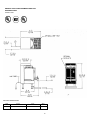
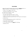
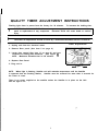
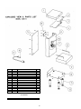
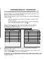
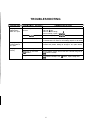
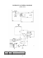
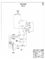
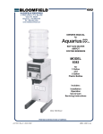
SATELLITE DOCKING STATION
BLOOMFIELD MODEL: SDS-1
TABLE OF CONTENTS
Introduction
General Layout Data Sheet
Features
Warranty
Safety
Installation Instruction
Leveling the Unit
Electrician's Installation Instructions
73342 Rev (-)
Page
Page
Page
Page
Page
Page
Page
Page
1
2
3
4
5
6
6
6
Initial Installation Instructions
Quality Timer Adjustment Instructions
Exploded View
Parts Identification
Ordering/Service Procedure
Troubleshooting
Schematic —
Wiring Diagram
Page
Page
Page
Page
Page
Page
Page
Page
6
7
8
8
9
10
12
12
Printed in December, 1997
INTRODUCTION
BLOOMFIELD MODEL: SDS-l
HI-QUALITY SATELLITE DOCKING STATION
Thank you for purchasing a Bloomfield Satellite Docking Station. You will achieve
maximum performance from this unit if you familiarize yourself with its many outstanding
features. Please take a few minutes to read through the owner’s manual. Proper
installation is very important if maximum performance and satisfaction are to be achieved.
If you have any difficulties, consult your nearest, Bloomfield Authorized Distributor. They
have the required expertise to provide the proper advice and assistance. If the Bloomfield
Distributor is unable to assist you, please contact the factory directly.
Please be certain the electrical connections are compatible, as improper connections
could damage the Unit and void the warranty.
Safe and satisfactory operation of your Bloomfield Satellite Docking Station depends to a
great extent upon its proper installation. This Satellite Docking Station must be installed
without alteration and in accordance with these printed instructions and applicable electrical
codes. The performance and safety of the Brewer can be greatly Impaired If It Is altered
in any way, or If installation deviates from the Instructions printed herein, and will not
be covered under any warranty service agreement.
This Bloomfield Docking Station has been designed with adjustment flexibility to cover a
wide spectrum of customer needs.
1
GENERAL LAYOUT DATA BLOOMFIELD SATELLITE
DOCKING STATION
MODEL: SDS-1
ELECTRICAL SPECIFICATIONS
Model
WATTS
VOLTS
AMPS
503-1
45 (with one Satellite)
120
.4
2
FEATURES
MODELS SDS-l SATELLITE DOCKING STATION manufactured by BloomfIeld Industries Inc., Is
designed to hold coffee at a correct temperature for serving.
0
Operates on 120 Volt, .4 Amp, 45 Watt service.
0
Safety feature including absence of any hot surfaces.
6
Automatic Start when Satellitte is in place,
0
Ideal for self service applications.
0
Auto safety electrical shut-off when Satellite is removed.
0
Adjustable non-skid rubber feet on brewer for easy leveling.
0
Adjustable coffee quality timer light which flashes at end of approved coffee holding time.
0
Optional Drip Tray.
0
Teflon color coded wiring, keyed to color tabs at connection points.
0
Unit size requires minimal counter space.
0
Satellite Brewer & Satellites OPTIONAL.
0
UL, CUL & NSF Listed UL & CUL: E9253) (NSF: Standard 4)
0
Manufactured in USA
3
WARRANTY POLICY
All electrical products manufactured by Wells/Bloomfleld are warranted against defects
in material and workmanship by our authorized service agents with:
o One (1) year replacement part warranty
0 One (1) year. on labor
0 All genuine. Wells/Bloomfield replacement parts are warranted for ninety (90) days
from date of purchase on non-warranty equipment. This parts warranty is limited
only to replacements of the defective part. Any use of non-genuine Bloomfield
parts completely voids any warranty.
Labor includes cost of service invoice and is limited travel time to a sixty (60) mile
radius (or up to a maximum of one hour) to the nearest authorized service agency
or one of it’s sub-service agencies. This service will be provided on the customers
premises for non-portable models. Portable models (a device with a cord and plug)
must be taken or shipped to the closest authorized service agency; transportation
charges prepaid. All labor shall be performed during regular working hours. Overtime
premium will be charged to the buyer.
In addition to this warranty policy are the following exceptions:
A.
Dispensers (i.e., tea and coffee) carry ninety (90) day parts replacement only.
Warranty does not include any coverage for:
Resetting the safety thermostats, circuit breakers, overload protectors, or fuse
replacements unless warranted conditions are caused.
All problems due to operation at voltage other than specified on equipment
nameplates - conversion to correct voltage must be the customer’s responsibility.
All problems due to electrical connections not made in accordance with electrical
code requirements and wiring diagrams supplied with the equipment.
All problems due to inadequate water supply, such as fluctuating, high or low
water pressure, etc.
All problems due to mineral/calcium deposits, or contamination from chlorides
and or chlorines. De-liming is considered a preventative maintenance function
and not covered by warranty.
0
Calibration of thermostat. Replacement of items subject to normal wear to Include
such items as knobs, baskets, grids, mechanical timers, and thermocouples. Normal
maintenance functions including lubrication, adjustment of thermostats, microswitches,
replacement of fuses, and Indicating lights.
0
Installation, labor, and job check-outs are not considered warranty.
4
THIS WARRANTY IS THE COMPLETE AND ONLY WARRANTY, EXPRESS OR IMPLIED IN LAW
OR FACT, INCLUDING BUT NOT LIMITED TO WARRANTIES OF MERCHANTABILITY OR FITNESS
_
FOR ANY PARTICULAR PURPOSE, AND/OR FOR DIRECT, INDIRECT OR CONSEQUENTIAL
DAMAGES IN CONNECTION WITH WELLS/BLOOMFIELD PRODUCTS. This warranty is void if it
is determined that upon inspection by an authorized Wells/Bloomfield dealer/distributor that
the equipment has been modified, misused, misapplied, Improperly installed, or damaged in
transit or by fire, flood or act of nature. All problems due to water supply, lime build-up,
or high or low water pressure are not covered by this warranty. It also does not apply If
the serial nameplate has been removed or service is performed by unauthorized personnel.
.
NOTE: A Warranty Statement and Complete Service Agency Listing with Warranty exclusions
is provided with each unit.
SATELLITE DOCKING STATION IS VOID IF:
Other than genuine Bloomfield replacement parts are used.
Unit is plugged into voltage other than specified on serial plate.
Recommended Bloomfield servicing procedures are not followed.
SAFETY
Knowledge of proper procedures is essential to the safe operation of electrically energized
equipment. In accordance with generally accepted product safety labeling guidelines for
potential hazards, the following 4 signal words are used throughout this chapter.
!
!
!
DANGER - Danger is used to indicate the presence of a hazard which will cause
severe personal injury, death, or substantial property damage in the event the
statement is ignored.
WARNING - Warning is used to indicate the presence of a hazard which can cause
severe personal injury, death, or substantial property damage in the event the
statement is ignored.
CAUTION - Caution is used to indicate the presence of a hazard which will or can
cause minor personal injury, or property damage in the event the statement Is
ignored.
NOTE - Note is used to notify personnel of installation, operation o& maintenance
information which is important, but not hazard related.
NOTE - This piece of equipment is made in the USA and has American sizes on
hardware. All metric conversions are approximate and can vary in size.
Hazard Communication Standard (HCS) - The procedures in this chapter include the
use of chemical products. These chemical products will be highlighted with bold
face letters followed by the abbreviation (HCS). See the Hazard Communication
Standard (HCS) Manual for the appropriate Material Safety Data Sheet(s) (MSDS).
5
INSTALLATION INSTRUCTION
READ THIS COMPLETELY BEFORE STARTING THE INSTALLATION `-
!
CAUTION: DO NOT plug in or energize this unlt until lnstallation Instructions are read
and followed. Damage to the Unit will occur If the Instructions are not followed.
To enable the installer to make a quality installation and hold delay time to a minimum,
the following suggestions and tests should be done before the actual unit installation is
begun.
LEVELING THE UNIT
:
Set Satellite Docking Station in operating location and level. For proper unit operation,
It is very important that the unit be level when It Is standing In Its proper operating
position. A spirit level should be place on the top plate of the unit, at the edge, as a
guide when making level adjustments. Level the unit from left to right and front to back
by turning the adjustable feet that support the unit.
!
CAUTION: Rubber feet must be Installed on each leg of the unit. Failure to do so
will result In movement of the Satellite Docking Station which can cause personal
Injury and/or damage to unlt.
ELECTRICIAN’S INSTALLATION INSTRUCTIONS
!
WARNING ELECTRICAL SHOCK HAZARD: Satellite Docking Station must be properly
grounded to prevent possible shock hazard. Electrlcal shock will cause death or
serious Injury.
The unit requires a dedicated power source capable of supplying: 120 Volt, A.C. (3) wire,
15 Amp Service.
The unit is shipped from the factory with a power cord.
INITIAL INSTALLATION INSTRUCTIONS
A
CAUTION: lnitial lnstallatlon should be performed by a qualified Installer or qualified
service technician. Improper Installation will damage the Satellite Docking Station.
Be sure all electrical connections are secure.
Plug in Satellite Docking Station
NOTE: Satellite Light will flash momentarily to initialize the timer when initially plugged
into electrical outlet. DO NOT plug in unit when Satellite is in place. This will cause light
to flash constantly.
Position Satellite onto the Satellite Docking Station to insure light is on (there may be
a slight delay before light comes on in some models)
The Light will start flashing after the preset time is reached.
in the SS1 Instruction Manual for more information.
6
See Satellite Operation Section
QUALITY TIMER ADJUSTMENT INSTRUCTIONS
Flashing light timer is preset from the factory for 30 minutes.
!
!
To increase the holding time:
ELECTRICAL SHOCK HAZARD: Disconnect power supply to Unit before removal of any
panel or replacement of any component. Electrical shock will cause death or serious
injury.
CAUTION: All adjustments should be made by a authorized Bloomfield Service Technician
I
Timer Adjustment
1. Unplug unit from the electrical outlet.
2. Remove Rear panel. (See item 5 on page 8)
3. Locate time control (See item 13 on page 8) and turn
clockwise to holding time maximum. (See Figure 1)
NOTE: Maximum allowable time is 120 minutes.
4. Replace Rear Panel.
5. Plug unit in.
- Figure 1 NOTE: When light is flashing, Satellite unit will maintain temperature until the Satellite
is removed from the Docking Station, Satellite must be removed for more than 4 seconds for
the Timer to reset.
There is no power supplied to the satellite unless the Satellite is in place on the Unit
and the light is on.
7
ITEM
1
2
3
4
5
6
7
8
9
10
11
12
13
15
16
17
SERVICE
8718-31
83081
83046
83077
83098
83107
83102
83105
35-210
6407-15
DESCRIPTION
TOP HOUSING WLD ASSY
PILOT LIGHT GREEN 120V
SHIELD FUNNEL
PLATE BTM TOP HOUSING
PANEL BACK *
BODY WLD ASSY
CONNECTOR ASSY
HANDLE GUIDE "L"
BASE WLD ASSY
PLATE BOTTOM
LEG 4" FLANGE. BLACK
FEET. RUBBER. BLACK
TIMER W/SPACER & NUT
SWITCH CHERRY W/SCREW
STRAIN RELIEF
CORD ASSY
QTY.
1
1
1
1
1
1
1
2
1
1
4
4
1
1
1
1
ACCESSORY
900014
DRIP TRAY
1
8
I
ORDERING/SERVICE PROCEDURE
Use only genuine Bloomfield replacement parts in this Satellite Docking Station. The
use of replacement parts other than those supplied by Bloomfield voids the warranty.
Parts are available at your Authorized Bloomfield Service Agency as provided in your
Warranty Statement and Service Agency Listing.
To find. the parts required to restore proper operation to the Satellite Docking Station,
proceed as follows:
1.Refer to the exploded views located in this chapter to identify the parts
needed. (Page 8)
2.Use the item number from the exploded view to locate the corresponding
parts in the parts identification Table. (Page 8)
Ordering Information - Once the parts needed are known, record the following
information from the Identification Name Plate on the side of the Unit and
Parts Identification Section on page 8.
Serial Number:
Model:
Part No.
Description
1
Part No.
I QtY
Description
I QtY I
I
I
I
I
How to order - For immediate shipment, call your local BLOOMFIELD INDUSTRIES
Authorized Service Agency.
Service information - To obtain service assistance in addition to that contained in this
chapter, call BLOOMFIELD in the U.S. at (702) 345-0444.
Be prepared to give the model and serial numbers of your Satellite Docking Station, as well
as the problem and the troubleshooting steps already taken, to the service technician when
calling for assistance.
Q
TROUBLESHOOTING
A
ELECTRICAL SHOCK HAZARD: Inspecting, testing and repair of electrical equipment should be performed only by qualified service personnel. The Satellite Docking
Station should be unplugged when servicing, except when electrical tests are
required. Electrical shock will cause serious Injury or death.
it is very important, when servicing equipment to:
1. Define the basic problem
2. Isolate the probable cause
3. Take corrective action regarding those items hampering proper operation of
the equipment.
it is usually relatively easy to define the basic problem, but sometimes very difficult to
pinpoint the precise cause.
A Troubleshooting guide is provided in this manual to suggest probable causes and
corrective actions for each. Obviously, if the cause is not isolated and corrected,
proper operation of the equipment cannot be restored.
Should the problem remain after exhausting the troubleshooting steps suggested, refer
to the Order/Service information section of this chapter. (page 9)
!
ELECTRICAL SHOCK HAZARD: Use extreme care during electrical circuit test. Live
circuits will be exposed. Electrical shook will cause serious injury or death.
10
TROUBLESHOOTING
CORRECTIVE ACTION
[ P R O B L E M ][ P R O B A B L E C A U S E ]
Quality light lo not
on/flashing when
Satellite is in place.
Satellite Receptical or SDS-l
Connector
Check Receptical and Connector Assembly, make sure all pins are
tight and in place.
Check ail soldered wiring.
~
Check continuity, replace if defective.
Snap Action Switch in Connector
Check continuity, replace if defective.
Satellite is not in proper position Place Satellite unit in proper position, making sure the, bottom dimples
on Satellite base are located on the matching dimples on the Brewer.
Quality light stays
on when Satellite is
not in place.
Snap Action Switch
Snap Action switch on Connector should open when Satellite is
removed from position, shutting off the light. if not, replace Switch.
Quality light flashes
constantly
Satellite is still in place
Remove Satellite for more than 4 seconds for timer to reset.
Satellite was in place when
timer initialized
Remove Satellite, Unplug unit for more than 4 seconds. Plug unit in
(with Satellite removed)
Quality Timer
Remove Satellite, Unplug unit for more than 4 seconds. Plug unit in
(with Satellite removed) If unit still flashes, replace Quality timer.
11
I‘
SCHEMATIC & WIRING DIAGRAM
(MODEL SDS-1)
MODEL:
VOLTS
WATTS:
SDS-1
120
45 W (USE WITH [1] 9105DS OR 9105DP)
12
13