1
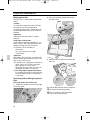
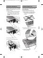
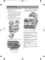
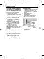
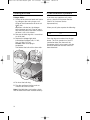
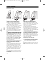
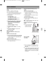
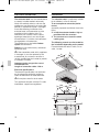
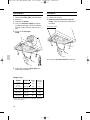
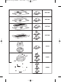
5750.197 457_Bo Umschl
DHL 53…
DHL 54…
DHL 55…
DHL 57…
DHL 75…
DHL 77…
04.10.2006
13:15 Uhr
und
de GebrauchsMontageanweisung
and
en Operating
installation instructions
de montage
fr Notice
et d’utilisation
en
nl Gebruiksmontageaanwijzing
per l’uso
it Instruzioni
e l’installazione
de uso
es Instrucciones
y montaje
pt Instruções de Serviço
e de Montagem
Internet: http://www.bosch-hausgeraete.de
Bosch Info-Team: de Tel. 01 80/5 30 40 50 (E 0,12/Min. DTAG)
Seite 1
5750.197 457+458.Bo/Si.qxd
24.01.2005
10:08 Uhr
Seite 6
Filter und Wartung
Aktivkohlefilter
Bei Dunstabzugshauben mit zwei
Filterkassetten:
Achtung: Die Halogenlampen müssen
ausgeschaltet und abgekühlt sein.
1. Drücken Sie die Raste an den Fettfiltern
in Pfeilrichtung ein und klappen Sie den
Fettfilter zuerst nur leicht nach unten.
Lösen Sie ihn indem Sie ihn zu sich herziehen.
Aus- und Einbauen des Aktivkohlefilters
Bei Dunstabzugshauben mit einer
Filtermatte:
1. Ausbau des Filters siehe Fettfilter.
❑ Das Drahtgitter wird beim Einbau
eines Aktivkohlefilters nicht mehr
benötigt.
2. Legen Sie den Aktivkohlefilter auf die
Filtermatte und klemmen Sie ihn ein.
2. Reinigen Sie die Fettfilter.
3. Setzen Sie die gereinigten Fettfilter
wieder ein.
6
3. Montieren des Filterrahmens.
❑ Siehe Fettfilter.
5750.197 457_Bo Umschl
04.10.2006
13:15 Uhr
Seite 2
de
Seite
2– 15
it
pagna
55– 67
en
page
16 – 28
es
página
68– 81
fr
pages
29 – 41
pt
página
82–94
nl
pagina
42 – 54
Gebrauchsanweisung:
Betriebsarten
Abluftbetrieb
❑ Der Lüfter der Dunstabzugshaube saugt
den Küchendunst an und leitet ihn durch
den Fettfilter ins Freie.
❑ Der Fettfilter nimmt die fettigen Bestandteile des Küchendunstes auf.
❑ Die Küche bleibt weitgehend frei von Fett
und Geruch.
D Bei Abluftbetrieb der Dunstabzugshaube und gleichzeitigem Betrieb
schornsteinabhängiger Feuerungen (wie
z. B. Gas-, Öl- oder Kohleheizgeräte,
Durchlauferhitzer, Warmwasserbereiter)
muss für ausreichend Zuluft gesorgt
werden, die von der Feuerstätte zur Verbrennung benötigt wird.
Ein gefahrloser Betrieb ist möglich, wenn
der Unterdruck im Aufstellraum der
Feuerstätte von 4 Pa (0,04 mbar) nicht
überschritten wird.
Dies kann erreicht werden, wenn durch
nicht verschließbare Öffnungen, z. B. in
Türen, Fenstern und in Verbindung mit
Zuluft-/Abluftmauerkasten oder durch
andere techn. Maßnahmen, wie gegenseitige Verriegelung o. ä., die
Verbrennungsluft nachströmen kann.
Bei nicht ausreichender Zuluft besteht
Vergiftungsgefahr durch zurückgesaugte
Verbrennungsgase.
2
Ein Zuluft-/Abluftmauerkasten allein stellt
die Einhaltung des Grenzwertes nicht
sicher.
Anmerkung: Bei der Beurteilung muss
immer der gesamte Lüftungsverbund der
Wohnung beachtet werden. Bei Betrieb von
Kochgeräten, z. B. Kochmulde und Gasherd wird diese Regel nicht
angewendet.
Wenn die Dunstabzugshaube im Umluftbetrieb – mit Aktivkohlefilter – verwendet wird,
ist der Betrieb ohne Einschränkung
möglich.
Umluftbetrieb
❑ Hierzu muss ein Aktivkohlefilter eingebaut werden (siehe Filter und Wartung).
Der Aktivkohlefilter kann beim Fachhandel erworben werden (siehe Sonderzubehör auf der letzten Seite).
❑ Der Lüfter der Dunstabzugshaube saugt
den Küchendunst an und leitet ihn durch
den Fett- und Aktivkohlefilter gereinigt in
die Küche zurück.
❑ Der Fettfilter nimmt die fettigen Bestandteile des Küchendunstes auf.
❑ Der Aktivkohlefilter bindet die Geruchsstoffe
5750.197 457+458.Bo/Si.qxd
24.01.2005
10:08 Uhr
Seite 16
Instructions for Use
Operating modes
Before using the first time
Exhaust-air mode
! The appliance is not intended for use
by young children or infirmed persons
without supervision.
Young children should be supervised to
ensure they do not play with the appliance.
❑ The ventilator fan draws the vapours
produced during cooking into the
extractor hood, where they pass
through the grease filter and out into the
open air.
❑ The grease filter absorbs the grease
contained in the vapours produced
during cooking.
❑ The kitchen is kept almost totally free
from grease and odours.
Circulating-air mode
❑ An activated carbon filter must be fitted
for this operating mode (see Filters and
maintenance).
Activated carbon filters can be
purchased from specialist outlets
(see Optional accessories on the last
page).
❑ The ventilator fan draws the vapours
produced during cooking into the
extractor hood, where they pass
through the grease filter and the activated carbon filter before the clean air is
discharged back into the kitchen.
❑ The grease filter absorbs the grease
contained in the vapours produced
during cooking.
❑ The activated carbon filter absorbs any
odorous substances.
Before using the first time
Important notes
This extractor hood complies with all
relevant safety regulations.
Repairs should only be carried out by
qualified specialists.
! If the connection cable of this appliance
is damaged, it must be replaced by the
manufacturer, his customer service or a
similarly qualified person in order to prevent
a hazardous situation.
Improperly executed repairs can give
rise to significant hazards for the user.
16
! The appliance should only be
connected up to the mains and taken into
use by a qualified specialist.
! Dispose of packaging materials
properly (see Installation instructions).
! Defective bulbs should be replaced
immediately to prevent the remaining bulbs
from overloading.
! Light bulbs must always be fitted
when the extractor hood is in use.
! Never operate the extractor hood
without a grease filter.
! Overheated fat or oil can easily catch
fire.
If you are cooking with fat or oil, e.g. chips,
etc., never leave the cooker unattended.
! Do not flambé food directly under the
extractor hood.
Risk of grease filter catching fire due
to flames.
!
!
The hotplates must always be covered
with a utensil.
!
Restrictions apply to the use of the
extractor hood over a solid-fuel burner
(coal, wood, etc.). (See Installation
instructions).
Gas hobs / Gas cookers
!
Do not use all the gas hotplates
simultaneously for a prolonged period
(max. 15 minutes) at maximum thermal
load, otherwise there is a risk of burns if
the housing surfaces are touched or a risk
of damage to the extractor hood. If the
extractor hood is situated over a gas hob,
operate the hood at maximum setting if
three or more gas hotplates are operated
simultaneously.
5750.197 457+458.Bo/Si.qxd
24.01.2005
10:08 Uhr
Seite 17
How to operate the extractor hood
Filters and maintenance
!
Various types of grease filter can be
used to absorb the grease contained in
the vapours produced during cooking.
The most effective method of removing vapours produced during cooking is
to:
❑ Switch the ventilator ON
as soon as you begin cooking.
❑ Switch the ventilator OFF
a few minutes after you have finished
cooking.
Operating controls on different
models
on
off
1
0
2
P
Light
Intensive setting
Fan settings
Light
P
3
2
1
Fleece grease filter
The filter mat is made from material that is
itself virtually non-inflammable.
Caution:
As it becomes more and more saturated
with grease however, the filter becomes
increasingly inflammable. The efficiency of
the extractor hood can also be adversely
affected.
Important:
Renewing the fleece filter at appropriate
intervals prevents the possibility of it
catching fire as a result of a build-up of
heat, such as occurs when deep-fat frying
or roasting is taking place.
Renewing the fleece filter:
❑ Under normal operating conditions
(1 to 2 hours per day), the fleece filter
will require replacing after 8 to 10
weeks. Printed fleece filters must be
renewed no later than when the coloured printing has started to fade.
❑ Use only original replacement filters.
In so doing you will ensure that safety
regulations are upheld and the extractor
hood performs as effectively as possible.
Intensive setting
Fan settings
Disposing of the old fleece grease filter:
! Fleece grease filters do not contain any
pollutants. They can be composted and
disposed of as biodegradable waste.
Note: The light can be switched on at any
time, including when the vapour extractor
tray has been pushed back into the hood.
17
5750.197 457+458.Bo/Si.qxd
24.01.2005
10:08 Uhr
Seite 18
Filters and maintenance
Metal grease filter
The filter mat is made of non-combustible
metal.
Caution:
As it becomes more and more saturated
with grease, the filter also becomes
increasingly inflammable. The efficiency of
the extractor hood can also be adversely
affected.
Important:
Clean the metal grease filter at regular
intervals.
Cleaning the metal filter:
Under normal operating conditions (1 to 2
hours per day), the metal grease filter will
require cleaning after 8 to 10 weeks.
❑ The filter can be cleaned in a
dishwasher.
This can however cause slight
discoloration.
Important:
Metal filters that are heavily saturated with
grease should not be cleaned at the same
time as any crockery, etc.
❑ If the filter mat is going to be cleaned by
hand, soak it first of all in a hot detergent solution for several hours.
Clean the filter with a brush, rinse it off
thoroughly and allow it to drip dry.
❑ Use only original replacement filters.
In so doing you will be ensuring that the
extractor hood performs as effectively
as possible.
2. Press the retaining spring and remove
the filter frame.
3. Remove the wire grille and replace the
filter mat.
Removing and installing the grease
filter
Extractor hoods with a filter mat:
1. Rotate the handles on the left and right
of the filter grille.
18
4. Install the filter frame in reverse sequence.
! Re-attach the retaining spring.
! The left and right sides of the filter
frame must lock into position!
5750.197 457+458.Bo/Si.qxd
24.01.2005
10:08 Uhr
Seite 19
Filters and maintenance
Activated carbon filter
Extractor hoods with two filter cartridges:
Warning: The halogen bulbs must be switched off and cool.
1. Depress the detent on the grease filters
in the direction of the arrow and fold
down the grease filter slightly. Detach
the grease filter by pulling it towards
yourself.
Removing and installing the activated carbon filter
Extractor hoods with a filter mat:
1. Remove the filter; see grease filter.
❑ The wire grille is no longer required
when an activated carbon filter is
installed.
2. Place the activated carbon filter on the
filter mat and clamp it in.
2. Clean the grease filters.
3. Re-insert the clean grease filters.
3. Install the filter frame.
❑ See grease filter.
19
5750.197 457+458.Bo/Si.qxd
24.01.2005
10:08 Uhr
Seite 20
Activated carbon filter
Extractor hoods with two filter cartridges:
1. Remove the filter cartridge.
❑ See grease filter.
2. Insert the screw through the wing nut
and the sleeve and screw in the middle
screw in the false bottom (required only
during the initial installation). Screw,
sleeve and wing nut are enclosed with
the activated carbon filter.
3. Using a screwdriver, press in the two
lugs on the false bottom. If a spacer rail
has been installed, it must be removed.
4. Tape over the activated carbon filter with
the enclosed sealing strip.
20
5. Insert the activated carbon filter at the
rear, fold up and lock in the middle with
the wing nut. If the spacer rail has been
removed, it must be re-installed.
6. Re-insert the two filter cartridges.
Removing the activated carbon filter:
❑ The activated carbon filter is removed in
reverse sequence.
Changing the activated carbon filter:
If used normally (1 to 2 hours daily), the
activated carbon filter should be changed
approx. once a year.
Activated carbon filters can be purchased
from SPECIALIST OUTLETS (see optional
accessories on the last page).
Use original filters only. This will ensure
optimum performance.
Disposing of the old activated carbon
filter:
Activated carbon filters do not contain any
pollutants. They can be disposed of e.g. as
residual waste.
5750.197 457+458.Bo/Si.qxd
24.01.2005
10:08 Uhr
Seite 21
Cleaning and care
Switch off the extractor hood and isolate by pulling out the mains plug or switching off the disconnector on the installation side.
❑ At the same time as you renew the
grease filter (see Filters and
maintenance), clean off any grease from
all accessible parts of the housing.
This significantly reduces the fire hazard
and ensures that the extractor hood
performs as effectively as possible.
❑ Clean the extractor hood with a hot
detergent solution or a mild window
cleaning agent.
❑ If the hood is extremely dirty (older
stains), use a liquid window cleaner.
❑ Do not scratch off dried-on dirt, but
wipe off with a damp cloth.
❑ Do not use scouring agents.
Warning: Clean the control buttons with a
mild detergent solution and a soft, damp
cloth only.
Painted, aluminium and plastic surfaces:
❑ Do not use scouring agents or abrasive
sponges.
❑ Do not use dry cloths.
❑ Do not use corrosive, acidic or alkaline
cleaning agents.
❑ Note: Do not use alcohol (spirit) on
plastic parts, otherwise the surface may
become matt in appearance.
❑ Caution! Ensure that the kitchen is adequately ventilated. Avoid naked flames.
Changing the bulbs
1. Switch off the extractor hood and isolate
by pulling out the mains plug or switching off the disconnector on the installation side.
2. Remove the filter frame.
❑ See grease filter.
3. Replace the bulb (standard filament
bulb, max 40 W, E14 bulb holder).
4. Attach the filter frame.
❑ See grease filter.
21
5750.197 457+458.Bo/Si.qxd
24.01.2005
10:08 Uhr
Seite 22
Cleaning and care
If you encounter a problem
Halogen bulbs:
1. Switch off the extractor hood and isolate
by pulling out the mains plug or switching off the disconnector on the installation side.
! When switched on, the halogen
bulbs become very hot. Even for some
time after the bulbs have been switched
off there is still a risk of burns.
2. Remove the bulb ring with a screwdriver
or similar tool.
3. Replace the halogen light bulb
(conventional halogen bulb, 12 Volt,
max. 20 Watt, G4 cap).
Caution: Refer to for plug-in
lampholder.
Take hold of the bulb with a clean cloth.
If you have any questions or if a fault
occurs, please call Customer Service.
(See list of Customer Service
representatives).
4. Re-insert the bulb ring.
5. Plug the appliance into the mains or
switch it on at the fuse box.
Note: If the light does not function, check
that the bulbs have been inserted correctly.
22
When you call, please quote the following:
E-Nr.
FD
Enter the relevant numbers into the box
above. The E-Nr. (product no.) and FD
(production date) are shown on the
nameplate which can be seen inside the
extractor hood after the filter frame has
been detached.
5750.197 457+458.Bo/Si.qxd
24.01.2005
10:08 Uhr
Seite 23
Installation Instructions:
Important information
! Old appliances are not worthless
rubbish. Valuable raw materials can be
reclaimed by recycling old appliances.
Before disposing of your old appliance, render it unusable.
! You received your new appliance in a
Additional information concerning gas
cookers:
! When installing gas hotplates, comply
with the relevant national statutory
regulations (e.g. in Germany: Technische
Regeln Gasinstallation TRGI).
protective shipping carton. All packaging
materials are environmentally friendly and
recyclable. Please contribute to a better
environment by disposing of packaging
materials in an environmentally-friendly
manner.
Please ask your dealer or inquire at your
local authority about current means of
disposal.
! Always comply with the currently valid
! The extractor hood can be used in
between the upper edge of the trivet
and lower edge of the extractor
hood:
650 mm.
exhaust air or circulating air mode.
! Always mount the extractor hood over
regulations and installation instructions supplied by the gas appliance
manufacturer.
! Only one side of the extractor hood may
be installed next to a high-sided unit or high
wall. Gap at least 50 mm.
! Minimum distance on gas hotplates
the centre of the hob.
! Minimum distance between electric hob
and bottom edge of extractor hood:
650 mm.
!The extractor hood must not be
installed over a solid fuel cooker – a
potential fire hazard (e.g. flying sparks) –
unless the cooker features a closed,
non-removable cover and all national
regulations are observed.
min 650
! The smaller the gap between the
extractor hood and hotplates, the greater
the likelihood that droplets will form on the
underside of the extractor hood.
23
5750.197 457+458.Bo/Si.qxd
24.01.2005
10:08 Uhr
Seite 24
Prior to installation
Exhaust-air mode
The exhaust air is discharged upwards
through a ventilation shaft or directly
through the outside wall into the open.
D Exhaust air should neither be directed
into a smoke or exhaust flue that is
currently used for other purposes, nor into a
shaft that is used for ventilating rooms in
which stoves or fireplaces are also located.
Local authority regulations must be
observed when discharging air into smoke
or exhaust flues that are not otherwise in
use.
D When the extractor hood is operated
in exhaust-air mode simultaneously with
a different burner which also makes use
of the same chimney (such as gas, oil or
coal-fired heaters, continuous-flow heaters,
hot-water boilers) care must be taken to
ensure that there is an adequate supply
of fresh air which will be needed by the
burner for combustion.
Safe operation is possible provided that the
underpressure in the room where the
burner is installed does not exceed 4 Pa
(0.04 mbar).
This can be achieved if the combustion air
can be replenished by being able to flow
through non-closeable openings such as in
doors, windows, wall ventilation boxes, or
by alternative technical measures such as
reciprocally shutting the other device off,
etc.
An air-intake/exhaust-air wall box by itself is
no guarantee that the limiting value will not
be exceeded.
24
Note: When assessing the overall
requirement, the combined ventilation
system for the entire household must be
taken into consideration. This rule does not
apply to the use of cooking appliances,
such as hobs and ovens.
All legal requirements concerning the
discharge of exhaust air must be observed.
Unrestricted operation is possible if the
extractor hood is used in recirculating mode
– with activated carbon filter.
The extractor hood should be fitted with a
one-way flap for exhaust-air mode if there is
not already one installed in the exhaust-air
pipe or wall box. If a one-way flap is not
enclosed with the appliance, purchase one
from a specialist outlet (see optional accessories on the last page).
Attaching the one-way flap
❑ Insert the two lugs on the one-way flap
into the holes on the air-pipe connector
or air outlet and lock into position.
! Before installing the one-way flap, ensure that the lettering or stamp is on the outside.
5750.197 457+458.Bo/Si.qxd
24.01.2005
10:08 Uhr
Seite 25
Prior to installation
Optimum performance of the extractor
hood:
❑ Short, smooth extraction pipe.
❑ As few pipe bends as possible.
❑ Largest possible pipe diameter (preferably 150 mm ø) and large pipe bends.
❑ Round pipes:
We recommend
for single-motor model,
inner diameter of at least 120 mm
for double-motor model.
inner diameter of at least 150 mm
❑ Flat ducts must have an inner crosssection equivalent to round pipes
which have an inner diameter of
120/150 mm.
120 mm l approx. 113 cm2
150 mm l approx. 177 cm2
❑ If pipe diameters differ: use sealing
strip.
❑ Ensure an adequate air supply for
exhaust-air mode.
Extractor hoods with 150 mm Ø air
outlet:
150 mm l extraction pipe
❑ Screw the reducing connector (see
optional accessories on the last page)
onto the air outlet.
❑ Attach the extraction pipe to the reducing connector.
150 mm l extraction pipe
❑ Attach the exhaust-air pipe directly to
the air outlet..
! If a one-way flap has been fitted, conduct a performance test.
Extractor hoods with rectangular air
outlet:
❑ Screw the enclosed
air-pipe connector
over the air outlet.
Pipe connection
Extractor hoods with 120 mm Ø air
outlet:
100 mm Ø extraction pipe
❑ Insert the reducing connector (see optional accessories on the last page) into the
air-pipe connector and then attach the
exhaust-air pipe.
120 mm Ø extraction pipe
❑ Attach the exhaust-air pipe directly to
the air-pipe connector.
Recirculated
air mode
❑ The air cleaned by an additional activated carbon filter is conveyed back into
the room.
❑ In recirculated air mode the exhaust opening must be protected by a grille (see
optional accessories on the last page) in
order to prevent a mechanical or electrical hazard.
25
5750.197 457+458.Bo/Si.qxd
24.01.2005
10:08 Uhr
Seite 26
Electrical connection
Installation
The extractor hood must be connected to
a correctly installed earthed socket only.
Attach the earthed socket as close to the
appliance as possible and in an accessible
position. If the earthed socket is no longer
accessible following installation of the
extractor hood, a disconnector must be
provided on the installation side. Disconnectors are switches with a contact
opening of more than 3 mm and all-pole
disconnection. LS switches and contactors
are regarded as disconnectors.
The appliance must be isolated before
repairs are carried out.
Repairs may be carried out by authorised
technicians only.
The extractor hood is particularly suitable
for installation in a flue or chimney.
To ensure optimum extraction performance
(especially important for kitchen island solutions):
❑ Install the extractor hood as high as
possible within the structure
❑ The structure must cover the entire
cooking area.
The following cutouts must be made for
the installation depending on the model:
Extractor hood with rocker switch, 53 cm
wide, 1-motor:
! If the connection cable of this appliance
m
in
0
is damaged, it must be replaced by the
manufacturer, his customer service or a
similarly qualified person in order to prevent
a hazardous situation.
Improper repairs may put the user at
considerable risk.
Length of connection cable: 1.20 m.
Electrical specifications:
The electrical specifications can be found
on the rating plate inside the appliance
when the filter frame has been removed.
1
min
3
60 -
15
2
50
0
-3
16
! Do not place hand in the air outlet.
This appliance complies with the EC radio
interference suppression regulations.
248
100
248
120
47 75
160
12
530
75
280
26
256
5750.197 457+458.Bo/Si.qxd
24.01.2005
10:08 Uhr
Seite 27
Installation
Extractor hood with slide control, 53 cm
wide, 1 and 2-motor:
m
in
5
35
1
min
3
2-
Extractor hood with slide control, 73 cm
wide, 1 and 2-motor
m
in
5
15
35
50
0
-3
1
min
2 -3
70
0
-3
16
16
248
150
248
120
348
150
55
35
95
160
9
9
530
380
348
120
55 95
35
160
730
100
225
346
150
496
100
225
380
120
150
346
696
160
310
250
380
530
120
160
230
9
15
230
310
60 80
9
730
60 80
95
95
346
380
250
346
27
5750.197 457+458.Bo/Si.qxd
24.01.2005
10:08 Uhr
Seite 28
Installation
Removal
1. Remove the filter grille (see operating
instructions).
2. Connect the power.
3. Press the extractor hood up into the
installation opening until the installation
aid locks into position at the front and
rear.
4. Screw in the extractor
hood.
1. Loosen the screws.
2. Hold the underside of the extractor
hood, Hold the underside of the extractor hood.
Installation spring
3. Lower the extractor hood and remove.
5. Insert and secure the filter grille (see
operating instructions).
Weight in kg:
Model
Width
Exhaust
air
Recircu
lated air
1-motor
Rocker switch
53 cm
5,0
6,3
1-motor
Slide control
53 cm
9,5
10,7
1-motor
Slide control
73 cm
10,3
11,6
2-motor
Slide control
53 cm
8,3
9,5
2-motor
Slide control
73 cm
8,7
9,9
Design changes with respect to technical development
shall remain withheld
28
5750.197 457_Bo Umschl
04.10.2006
13:15 Uhr
Seite 3
DHZ 2100
280
0
53
280
53
280
53
DHZ 7204
0
0
30
0/7
380
53
380
53
DHZ 7304
DHZ 7305
30
0/7
461423
30
280
5
30 0
0/773
55330/
3803
80
481051
3030
7
00/7/
5
533
38308
0
0
28
0
53
095660
38
0
38
0
30
/7
30
5
30
0/7
53
5750.197 457_Bo Umschl
04.10.2006
13:15 Uhr
Robert Bosch Hausgeräte GmbH
Seite 4
5750 197457
Printed in Germany
1006 Hi.


![[de] Gebrauchs- und Montageanleitung 2 [en] Instructions](http://vs1.manualzilla.com/store/data/006783472_1-9623bc8bb4187c1cd6f5b4be12ce6579-150x150.png)