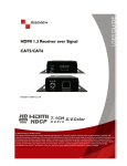
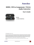
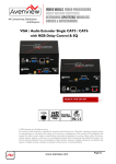
1
Cat5 DVI-D + Audio Series User’s Guide © 2008 Avenview™ Inc. All rights reserved. The contents of this document are provided in connection with Avenview Inc. (“Avenview”) products. Avenview makes no representations or warranties with respect to the accuracy or completeness of the contents of this publication and reserves the right to make changes to specifications and product descriptions at any time without notice. No license, whether express, implied, or otherwise, to any intellectual property rights is granted by this publication. Except as set forth in Avenview Standard Terms and Conditions of Sale, Avenview assumes no liability whatsoever, and disclaims any express or implied warranty, relating to its products including, but not limited to, the implied warranty of merchantability, fitness for a particular purpose, or infringement of any intellectual property right. Reproduction of this manual, or parts thereof, in any form, without the express written permission of Avenview Inc. is strictly prohibited. Disclaimer While every precaution has been taken in the preparation of this document, Avenview Inc. assumes no liability with respect to the operation or use of Avenview hardware, software or other products and documentation described herein, for any act or omission of Avenview concerning such products or this documentation, for any interruption of service, loss or interruption of business, loss of anticipatory profits, or for punitive, incidental or consequential damages in connection with the furnishing, performance, or use of the Avenview hardware, software, or other products and documentation provided herein. Avenview Inc. reserves the right to make changes without further notice to a product or system described herein to improve reliability, function or design. With respect to Avenview products which this document relates, Avenview disclaims all express or implied warranties regarding such products, including but not limited to, the implied warranties of merchantability, fitness for a particular purpose, and non-infringement. www.avenview.com 1 Table of Contents Getting Started ....................................................................................................................................... 3 Key Features ........................................................................................................................................... 3 Panel Description ................................................................................................................................... 4 DVI-C5-2 2 Port DVI-D + Audio Transmitter ....................................................................................... 4 DVI-C5-4 4 Port DVI-D + Audio Transmitter ....................................................................................... 4 DVI-C5-8 8 Port DVI-D + Audio Transmitter ....................................................................................... 5 Cable and Accessories ............................................................................................................................ 5 Installation and Operation ..................................................................................................................... 6 DVI-C5-LC-R Transmitter Installation ................................................................................................. 6 Selection of Cable............................................................................................................................... 6 Multi-Port DVI-C5-2/4/8 Transmitter Installation.............................................................................. 8 Monitor and Speaker Connection through RJ45 and RJ11 Ports ....................................................... 9 Installation of Multiple Transmitters ........................................................................................... 10 Specifications ....................................................................................................................................... 11 DVI Transmitter and Transceiver ..................................................................................................... 11 www.avenview.com 2 Getting Started The Cat5/5e/6 DVI-D + Audio Extender system consists of a Transmitter and a Receiver. The system can extend DVI-D and audio signals over Cat5/5e/6 cable and 4-wire phone cable. By taking advantage of low-cost Cat5/5e/6 FTP cable, the Cat5 DVI-D Extender can simplify installation, extend AV signal and save cost. The Cat5 DVI-D Extender system is perfect for digital signage and public information display applications where crystal-clear, high-resolution digital video needs to be shown without distance limitations. Key Features Multiply one DVI-D and Audio source to 2/4/8 DVI-D and Audio outputs over Cat 5/5e/6 and 4-wire phone cable. Video Amplifier Bandwidth: 1.65GHz Maximum distance and resolution between Transmitter and Receiver are: DVI Input: Transmitting over standard DVI cable up to 10 meters (30 feet) DVI Output: Transmitting over standard DVI cable at 1920x1200 up to 10 meters (30 feet) RJ45 Output and using longer range Receiver DVI-C5-LC-R: - 800x600 @ 100 meters (330 feet) - 1024x768 @ 70 meters (230 feet) - 1280x1024 @ 60 meters (200 feet) - 1920x1200 @ 35 meters (115 feet) DVI Input / Output Connector: DVI-D Audio Type and Distance: Stereo over 4-wire phone cable up to 100 meters (330 feet) Input for one DVI-D + Audio, Output for one DVI-D + Audio connection and 1/2/4/8 sets of RJ45 and RJ11 connections to transmit DVI-D and Audio signal using Cat 5/5e/6 and 4-wire phone cable. Built-in EDID simulation in Receivers. Computer can boot up DVI signal without connecting a local monitor. LED Status to indicate the DVI activity. Stackable capacity to expand the AV broadcasting. Magnetic pad and attachable metal plate for single port receiver, initial preset range of frequency is up to 1920x1200 www.avenview.com 3 Panel Description DVI-C5-2 2 Port DVI-D + Audio Splitter / Extender DVI-C5-4 4 Port DVI-D + Audio Splitter / Extender www.avenview.com 4 DVI-C5-8 8 Port DVI-D + Audio Transmitter Cable and Accessories DVI Integrated AV Cable 1.8m www.avenview.com 5 Installation and Operation DVI-C5-LC-R Installation a. Device Connection: Plug power adapter to DVI-C5-LC-R, the orange LED above RJ45 should turn ON to indicate the power on status. The other LED should turn off, since there is no input of video signal from “ SYSTEM LINK” port. b. The “STATUS” LED in the front panel will turn ON as the EQ/FOCUS control switch to the left end and the EQ/FOCUZ will stay on AUTO. This will not function until the Receiver gets video signal from “SYSTEM LINK” port. c. Connect DVI monitor’s DVI cable to the Receiver. Selection of Cable a. Most makes and versions of Cat 5/5e/6 cables will work with DVI-C5-LC-R Receiver. However, since the quality and characteristics of Cat 5/5e/6 cables varies it has been found that some perform better than others. The major factor influencing the transmitting distance is the skew property of the cables. Skew represents the difference in propagation delay between the fastest and slowest set of wire pairs. A lower skew will mean a longer video transmitting distance. www.avenview.com 6 b. Skew Property: A Cat 5/5e/6 cable with a skew lower than 15ns/100m should enable a cascading length of < 80m (275 ft) at 800x600, <50m at 1024x768, and < 40m at 1280x1024. c. Termination: The RJ45 terminations to the Cat 5/5e/6 cable must be made to the EIA 568B specifications. 1. 5. Orange White Blue White 2. Orange 3. Green White 6. Green 7. Brown White The EIA/TIA definition of 568B in the pin assignment 4. 8. Blue Brown PAIR 3 PAIR 2 PAIR 1 PAIR 4 JACK POSITION www.avenview.com 7 d. Connect the Cable: Plug one end of the cable to DVI-C5-LC-R Receiver’s RJ45 “SYSTEM LINK” port. The Receivers connected monitor should display now and the green LED above DVI-C5-LC-R’s RJ45 port should turn ON to reflect the DVI signal activation. For DVI-C5-LC-R, you can manually adjust the EQ/FOCUS to have the best DVI display. The display DVI resolution will also relate to the distance been extended. It will be better to test prior to actual installation and should not exceed the suggested frequency and corresponding distance. Installation Diagram of DVI-C5-LC-R Multi-Port DVI-C5-2/4/8 Splitter / Extender Installation a. First Time Setup: Turn off the DVI output device (PC or DVD Player) and monitors. b. Connection: Connect local DVI monitor and speaker to the “VIDEO/AUDIO OUT” of the transmitter and take one DVI integrated cable DVI-C5-180AT), plug DVI end to “VIDEO/AUDIO IN” port of transmitter and the other end of the cable to PC’s DVI-D video and speaker ports. c. Connect power adapter. d. Turn ON your DVI output device and monitor to confirm the function of display. The “LINK” LED of the transmitter should turn Orange to indicate the connection of a local DVI monitor and the “ACTIVE” LED should turn Blue to indicate an activated DVI-D signal. e. The transmitter has built in an EDID simulator, when you connect local DVI monitor, the transmitter will automatically record the EDID from DVI monitor. When you not connecting DVI monitor locally, the transmitter will simulate the EDID communication like a regular monitor and activate the DVI signal of PC. www.avenview.com 8 Local Connection of Multi-Port Transmitter Monitor and Speaker Connection through RJ45 and RJ11 Ports a. Refer to previous section for Receiver to install and prepare the cable to be connected. b. RJ45 VIDEO with DVI-C5-LC-R: If the video connection is HDMI type, then you will need to use appropriate DVI-HDMI adapter to connect. The supported DVI-D resolution and distance is similar to regular DVI cable. It supports 800x600@100m, 1024x768@70m, 1280x1024@60m, 1920x1200@35m. c. RJ11 AUDIO: The RJ11 ports in the back of the Transmitter support Stereo Audio for each connector. Prepare one 4-wire phone cable or use 4 wires out of the Cat 5/5e/6 cable to make the RJ11 connector. The pin definition of RJ45 is one to one and the supported length is greater than 50 meters (longer than the supported length of DVI-D) Connection Diagram of 2-Port Transmitter www.avenview.com 9 General Troubleshooting Problem Possible Solution Off-Center Screen Image, Odd Colors or No Picture No Image Try adjusting the brightness, sharpness, contrast, and color balance controls of your monitor. Try adjusting the centering and positioning controls of your monitor to position the picture on the screen. Ensure that the monitor cable is securely fastened to the DVI and Monitor port. Installation of Multiple Transmitters a. Multiple Transceivers: By using additional DVI-C5-R Transceivers, it is possible to extend the system almost indefinitely to remote DVI-D displays. b. From “VIDEO / AUDIO OUT”: Use one set of standard DVI/Audio cable. Connect one end from “VIDEO / AUDIO OUT” of first layers Transmitter and the other end to “DVI / AUDIO IN” port of the second layer’s Transmitter (as shown below). Installation Diagram of Multiple DVI Transmitters www.avenview.com 10 Specifications DVI Transmitter and Splitter / Extender Model Description Input Output Max Distance and Resolution Signal Type Power Consumption Dimension (LxWxH) mm DVI-C5-LC-R 1 Port DVI-D Transmitter DVI-C5-2 2 Port DVI-D Splitter Extender DVI-C5-4 DVI-C5-8 4 Port DVI-D 8 Port DVI-D Splitter Extender Splitter Extender DVI Female x 1 DVI Male x 1 Audio x 1 DVI Female x 1 DVI Female x 1 DVI Female x 1 Audio x 1 Audio x 1 Audio x 1 RJ45 x 1 RJ45 x 2 RJ45 x 4 RJ45 x 8 RJ11 x 2 RJ11 x 4 RJ11 x 8 DVI Input: 10m (33ft) transmitting over standard DVI cable DVI Output: Maximum Resolution of 1920 x 1200 @ 10m (33ft) RJ45 Output: < 100m (330ft) @ 800 x 600 < 70m (230ft) @ 1024 x 768 < 60m (200ft) @ 1280 x 1024 <35m (120ft) @ 1920 x 1200 DVI-D DC 5V, 250mA DC 5V, 800mA DC 5V, 1000mA DC 5V, 1200mA Compact 1U 1U 1U www.avenview.com 11 www.avenview.com 12