1
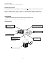
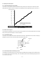
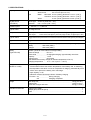
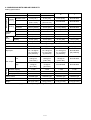
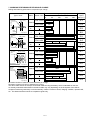
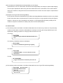
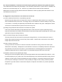
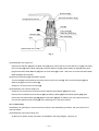
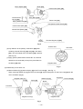
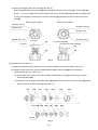
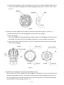
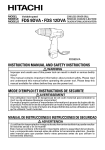
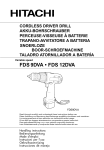
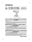
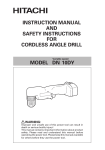
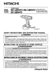
MODEL
FDS 12DVA
POWER TOOLS
CORDLESS DRIVER DRILL
FDS 12DVA
LIST No. F835
TECHNICAL DATA
AND
SERVICE MANUAL
Nov. 1999
SPECIFICATIONS AND PARTS ARE SUBJECT TO CHANGE FOR IMPROVEMENT
F
REMARK:
Throughout this TECHNICAL DATA AND SERVICE MANUAL, a symbol(s)
is(are) used in the place of company name(s) and model name(s) of our
competitor(s). The symbol(s) utilized here is(are) as follows:
Competitors
Symbols Utilized
Company Name
Model Name
B
BOSCH
PSR12VES-2
J
RYOBI
CTH1202K2
Notice for use
Specifications and parts are subject to change for improvement.
Refer to Hitachi Power Tool Technical News for further information.
CONTENTS
Page
[ Business Section ]
1. PRODUCT NAME
• • • • • • • • • • • • • • • • • • • • • • • • • • • • • • • • • • • • • • • • • • • • • • • • • • • • • • • • • • • • • • • • • • • • • • • • • • • • • • • • • • • • • • • • • • • • • • • • • • • • • • • • • • • • • • • • • • • • • • • •
• • • • • • • • • • • • • • • • • • • • • • • • • • • • • • • • • • • • • • • • • • • • • • • • • • • • • • • • • • • • • • • • • • • • • • • • • • • • • • • • • • • • • • • • • • • • • • • • • • • • • • • • • •
1
• • • • • • • • • • • • • • • • • • • • • • • • • • • • • • • • • • • • • • • • • • • • • • • • • • • • • • • • • • • • • • • • • • • • • • • • • • • • • • • • • • • • • • • • • • • • • • • • • • • • • • • • • • • • • • • • • • • • • • • • • •
1
2. MARKETING OBJECTIVE
3. APPLICATIONS
1
4. SELLING POINTS
• • • • • • • • • • • • • • • • • • • • • • • • • • • • • • • • • • • • • • • • • • • • • • • • • • • • • • • • • • • • • • • • • • • • • • • • • • • • • • • • • • • • • • • • • • • • • • • • • • • • • • • • • • • • • • • • • • • • • •
4-1. Selling Point Descriptions
5. SPECIFICATIONS
1
•••••••••••••••••••••••••••••••••••••••••••••••••••••••••••••••••••••••••••••••••••••••••••••••••••••••
2
• • • • • • • • • • • • • • • • • • • • • • • • • • • • • • • • • • • • • • • • • • • • • • • • • • • • • • • • • • • • • • • • • • • • • • • • • • • • • • • • • • • • • • • • • • • • • • • • • • • • • • • • • • • • • • • • • • • • • • •
3
6. COMPARISONS WITH SIMILAR PRODUCTS
• • • • • • • • • • • • • • • • • • • • • • • • • • • • • • • • • • • • • • • • • • • • • • • • • • • • • • • • • • • • • • • • • • • • • • • • • • • •
7. WORKING PERFORMANCE PER SINGLE CHARGE
••••••••••••••••••••••••••••••••••••••••••••••••••••••••••••••••
5
• • • • • • • • • • • • • • • • • • • • • • • • • • • • • • • • • • • • • • • • • • • • • • • • • • • • • • • • • • • • • • • • • • • • • • • • • • • • • • • • • •
6
• • • • • • • • • • • • • • • • • • • • • • • • • • • • • • • • • • • • • • • • • • • • • • • • • • • • • • • • • • • • • • • • • • • • • • • • • • • • • • • • • • • • • • • • • • • • • • • • • • • • • • • • • • • • • • • • •
6
8. PRECAUTIONS IN SALES PROMOTION
8-1. Safety Instructions
4
8-2. Inherent Drawbacks of Cordless Driver Drills Requiring Particular Attention During
Sales Promotion
••••••••••••••••••••••••••••••••••••••••••••••••••••••••••••••••••••••••••••••••••••••••••••••••••••••••••••••••••••
9. REFERENCE MATERIALS
• • • • • • • • • • • • • • • • • • • • • • • • • • • • • • • • • • • • • • • • • • • • • • • • • • • • • • • • • • • • • • • • • • • • • • • • • • • • • • • • • • • • • • • • • • • • • • • • • • • • • • • • •
9-1. Speed Control Mechanism
8
9
• • • • • • • • • • • • • • • • • • • • • • • • • • • • • • • • • • • • • • • • • • • • • • • • • • • • • • • • • • • • • • • • • • • • • • • • • • • • • • • • • • • • • • • • • • • • • • • • • • • • •
9
• • • • • • • • • • • • • • • • • • • • • • • • • • • • • • • • • • • • • • • • • • • • • • • • • • • • • • • • • • • • • • • • • • • • • • • • • • • • • • • • • • • • • • • • • • • • • • • • • • • • • • • • • • • • • • • • • • • • • • • • •
10
[ Service Section ]
10. REPAIR GUIDE
10-1. Precautions in Disassembly and Reassembly
• • • • • • • • • • • • • • • • • • • • • • • • • • • • • • • • • • • • • • • • • • • • • • • • • • • • • • • • • • • • • • • • • • • • • • • •
• • • • • • • • • • • • • • • • • • • • • • • • • • • • • • • • • • • • • • • • • • • •
16
• • • • • • • • • • • • • • • • • • • • • • • • • • • • • • • • • • • • • • • • • • • • • • • • • • • • • • • • • • • • • • • • • • • • • •
17
10-2. Precautions in Disassembly and Reassembly of Battery Charger
11. STANDARD REPAIR TIME (UNIT) SCHEDULES
10
[ Appendix ]
Assembly Diagram for FDS 12DVA
•••••••••••••••••••••••••••••••••••••••••••••••••••••••••••••••••••••••••••••••••••••••••••••••••
18
1. PRODUCT NAME
Hitachi 12 V Cordless Driver Drill, Model FDS 12DVA
2. MARKETING OBJECTIVE
Since the sales initiation of economically priced cordless driver drills
FDS series, they have been well received
over a period of 4 years in international markets. As a result of innovative technical research and development
program for operability, overload durability and market price competitiveness, the Model FDS 12DVA has been
developed to enhance the market share of Hitachi Cordless Power Tools. Vigorous sales promotion is anticipated
with concurrent introduction of new Model FDS 9DVA.
3. APPLICATIONS
Tightening and loosening wood screws, self-tapping screws and machine screws
Drilling into wood materials, plastic, mild steel and aluminum
4. SELLING POINTS
22-position adjustable
torque setting
Two speed transmission with
one-touch speed shift knob
Variable torque setting
for fastener tightening
Motor with cooling fan
10 mm keyless chuck
Variable speed switch
with braking function
Push-button type
reversing switch
Equipped with feedback
power control
1.4 Ah cassette battery
--- 1 ---
4-1. Selling Point Descriptions
4-1-1. 22-Position Adjustable Torque Setting
The number of clutch positions has been increased from the previous five to twenty-two to ensure finer torque
setting than that of previous model, and therefore, the operability has been significantly improved. (See Fig. 1.)
Torque (N•m) (kgf•cm)
5.9
60
5.4
55
4.9
50
4.4
45
3.9
40
3.4
35
2.9
30
2.5
25
2.0
20
1.5
15
1.0
10
Clutch position
Adjustable torque is about 2 kgf•cm
at each click within the torque range
of 10 --- 60 kgf•cm.
1
•
3
•
5
•
7
•
9
•
11
•
13
•
15
•
17
•
19
•
•
22
Fig. 1 Clutch torque
4-1-2. Motor with Cooling Fan
The cooling fan incorporated in the motor and the air vents provided in its outer frame greatly enhance the cooling
effect, ensuring improved durability in continuous operation.
4-1-3. 10 mm Keyless Chuck
The keyless chuck facilitates fast and easy replacement of driver bits. Replacement can be carried out simply by
holding the ring with one hand, while turning the sleeve with the other hand.
Tighten
Driver bit
Loosen
Ring
Sleeve
Fig. 2
4-1-4. Variable Speed Switch with Braking Function
The braking function allows the driver unit to stop rotation immediately when the trigger switch is released, which
is a convenient feature during actual working. Also, the feedback system ensures a sufficiently large torque even
in the variable speed range.
--- 2 ---
5. SPECIFICATIONS
Capacity
Screwdriver Machine screw
6 mm (1/4")
5.5 x 63 mm (#12 x 2-1/2")
Wood screw
Drill
Metal
Mild steel 12 mm (15/32") [thickness 1.6 mm (1/16")]
Aluminum 15 mm (19/32") [thickness 1.6 mm (1/16")]
Wood
21 mm (13/16") [thickness 18 mm (11/16")]
• • • • • • • •
• • • • • • • • • • • •
• • • • • •
• • • • • • • • • • • • • • • • • • • • • •
Keyless chuck
(10TLRE-N)
Mount type
Diameter
Rotation speed
0 --- 350 /min, 0 --- 1,050 /min
Type of motor
DC magnet motor
Torque
Slip torque
Max. torque
Screw-on (UNF 3/8" --- 24")
0.8 --- 10 mm (1/32" --- 3/8")
• • • • • • • •
•••••••
1.0 --- 5.9 N•m, 10 --- 60 kgf•cm (9 --- 52 in-lbs.) [22 stages]
Low 21.6 N•m, 220 kgf•cm (191 in-lbs.) High 6.9 N•m, 70 kgf•cm (61 in-lbs.)
Type of switch
Trigger switch with push button for forward and reverse rotation changeover (w/o stopper)
Type of handle
T-type
Enclosure
Body
Battery
Charger
• • • • • • • • • • • • • • • • • • • • • •
• • • • • • • • • • • • • • • • • • •
Battery
(Type FEB 12S)
• • • • • • • • • • • • • • • • • •
Glassfiber reinforced polycarbonate resin (moss green)
ABS resin (black)
ABS resin (black)
Sealed cylindrical nickel cadmium storage battery
Nominal voltage
DC 12 V
Nominal life
Charging/discharging: approximately 500 times
Capacity
1.4 Ah
Charging time
60 minutes
(with standard accessory charger at ambient temperature of 20 ˚C)
Charging temperature
10 ˚C --- 40 ˚C (50 ˚F --- 104 ˚F)
• • • • • • • • • • • • • • •
• • • • • • • • • • • • • • • • • • • • •
• • • • • • • • • • • • • • • • • • • • • • • • • •
• • • • • • • • • • • • • • • • • •
• • • • • • •
Charger
(Model UC 12SD)
Overcharge prevention circuit:
A thermostat monitors the surface temperature of the battery and, on detecting
the temperature rise which occurs on completion of charging, automatically turns
off the unit to prevent the battery from overcharge.
Input capacity: 51 W
Indication method: Pilot lamp indicator of battery charging
Function: On
During charging
Off
Charging completed
• • • • • • • • • • • • • • • • • • • • •
• • • • • • • • • • • • • • • • • • • • •
Weight
Main body unit
Charger unit
Gross with charger and case
• • • • • • • • • • • • • • • • • • • • • • • • • • • • • • • • • • • • • • • • • • • • • • • • • • • • • • • • • • • • • • • • • • • • • • • • • • • • •
Standard accessories
1.6 kg (3.4 Ibs.)
1.4 kg (3.1 Ibs.)
5.0 kg (11.0 Ibs.)
• • • • • • • • • • • • • • • • • • • • • • • • • • • • • • • • • • • • • • • • • • • • • • • • • • • • • • • • • • • • • • • • • • • • • • • • • •
• • • • • • • • • • • • • • • • • • • • • • • • • • • • • • • • • • • • • • • • • • • • • • • • • • • • •
Charger (UC 12SD)
Phillips (plus) driver bit (No.2)
Case
• • • • • • • • • • • • • • • • • • • • • • • • • • • • • • • • • • • • • • • • • • • • • • • • • • • • • • • • • • • • • • • • • • • • • • • • • • • • • • • • • • • • • • • •
• • • • • • • • • • • • • • • • • • • • • • • • • • • • • • • • • • • • • • • • • • • • • • • • • • • • • • • • • • • • • • • • • • • • • • • • • •
• • • • • • • • • • • • • • • • • • • • • • • • • • • • • • • • • • • • • • • • • • • • • • • • • • • • • • • • • • • • • • • • • • • • • • • • • • • • • • • • • • • • • • • • • • • • • • • • • • • • • • • • • • • • • •
--- 3 ---
1
1
1
6. COMPARISONS WITH SIMILAR PRODUCTS
Catalog specifications
Maker
HITACHI
HITACHI
Model
FDS 12DVA
FDS 12DV
6 mm (1/4")
6 mm (1/4")
Max. capacity
Machine screw
Screw
driving
Drilling
Rotation
speed
Wood screw
J
8 mm (5/16")
Not indicated
Not indicated
Not indicated
Mild steel
12 mm (15/32")
10 mm (3/8")
12 mm (15/32")
Not indicated
Aluminum
15 mm (19/32")
10 mm (3/8")
15 mm (19/32")
Not indicated
Wood
21 mm (13/16")
18 mm (23/32")
20 mm (25/32")
Not indicated
Low
0 --- 350 /min
0 --- 290 /min
0 --- 400 /min
0 --- 300 /min
High
0 --- 1,050 /min
0 --- 900 /min
0 --- 1,150 /min
0 --- 1,000 /min
Keyless
Keyless
Keyless
Keyless
10 mm (3/8")
10 mm (3/8")
10 mm (3/8")
10 mm (3/8")
DC magnet motor
DC magnet motor
DC magnet motor
DC magnet motor
Type
Drill
chuck
5.5 mm dia. x 63 mm length 5.5 mm dia. x 63 mm length
(#12 x 2-1/2)
(#12 x 2-1/2")
B
Capacity
Motor
2-Speed transmission
Electric brake
Gear changeover type 2-speed transmission
Equipped
Equipped
Equipped
Equipped
1.0 --- 5.9 N•m
10 --- 60 kgf•cm
(9 --- 52 in-lbs.)
[22 positions]
1.0 --- 4.9 N•m
10 --- 50 kgf•cm
(9 --- 43 in-lbs.)
[5 positions]
1.0 --- 8.0 N•m
10 --- 82 kgf•cm
(9 --- 71 in-lbs.)
[5 positions]
Not indicated
[23 positions]
Low
21.6 N•m
220 kgf•cm
(191 in-lbs.)
17.6 N•m
180 kgf•cm
(156 in-lbs.)
16.0 N•m
163 kgf•cm
(142 in-lbs.)
Not indicated
High
6.9 N•m
70 kgf•cm
(61 in-lbs.)
5.9 N•m
60 kgf•cm
(52 in-lbs.)
Not indicated
Not indicated
Nominal capacity
1.4 Ah
1.3 Ah
1.4 Ah
1.3 Ah
Nominal voltage
12 V
12 V
12 V
12 V
Charging time*
60 minutes
60 minutes
60 minutes
60 minutes
Battery mount
Cassette type
Cassette type
Cassette type
Cassette type
Overall length
220 mm (8-21/32")
223 mm (8-25/32")
219 mm (8-5/8")
250 mm (9-27/32")
Weight
1.6 kg (3.4 lbs.)
1.6 kg (3.5 lbs.)
1.6 kg (3.5 lbs.)
1.6 kg (3.5 lbs.)
Slip torque
Battery
Max. torque
Remarks*
• • • • • • • •
Charging time varies depending on the type of charger to be used.
--- 4 ---
7. WORKING PERFORMANCE PER SINGLE CHARGE
Drilling and fastening performance comparison per charge
Working capacity (*1)
Type of work
Mild steel
Maker
T1.6 (1/16")
Model name *0
0
*250
50
6.5 mm dia. (1/4")
American
pine
FDS 12DV
60
10.3
40
6.9
55
8.5
FDS 12DVA
205
18 mm dia. (11/16")
HITACHI
215
FDS 12DV
140
B
Wood boring
<Low speed>
4.7
FDS 12DV
85
5.9
45
B
4.6
70
J
FDS 12DVA
12 mm (15/32")
4.3
85
6.0
<Low speed>
Machine
screw
6 mm (1/4")
4.4
FDS 12DVA
HITACHI
Wood screw
3.5
3.1
195
J
63 mm (2-1/2")
5.5 mm dia. (#12)
American
pine
Driling
speed
(sec./pc.)
9.3
J
T18 (11/16")
*1000
200
55
B
<High speed>
*750
150
FDS 12DVA
HITACHI
HSS
drill bit
*500
100
HITACHI
FDS 12DV
*850
*895
*650
B
*745
J
<High speed>
0.9
1.0
0.8
0.9
Remarks* Number of machine screws fastened per charge
Remarks*1 Number of holes or fasteners per charge
The above table shows an example of test data obtained using the battery which is standard for this tool.
As actually measured values listed in the above table may vary depending on the sharpness of the drill bit,
workpiece hardness (particularly in wood materials), moisture content of wood, charging condition, operator skill,
etc. This data should be used as a comparative guide only.
--- 5 ---
8. PRECAUTIONS IN SALES PROMOTION
8-1. Safety Instructions
In the interest of promoting the safest and most efficient use of the Model FDS 12DVA Cordless Driver Drill by all
of our customers, it is very important that at the time of sale, the salesperson carefully ensures that the buyer
seriously recognizes the importance of the contents of the Handling Instructions, and fully understands the
meaning of the precautions listed on the Caution Plate and Name Plate attached to each tool.
A. Handling Instructions
Salespersons must be thoroughly familiar with the contents of the Handling Instructions in order to give pertinent
advice to the customer. In particular, they must have a thorough understanding of the precautions for use of the
cordless tools which are different from those of ordinary electric power tools.
(1) Before use, ensure that the unit is fully charged.
New units are not fully charged. Even if the units were fully charged at the factory, long periods of inactivity,
such as during shipping, cause the storage battery to lose its charge. Customers must be instructed to fully
charge the unit prior to use.
(2) When charging storage batteries, use only the exclusive Model UC 12SD Charger provided with the tool.
Because of the designed rapid-charging feature (about one hour), use of other battery chargers is hazardous.
(3) Connect the Charger to an AC power outlet only.
Use of any other power source (DC outlet, fuel powered generator, etc.) will cause the Charger to overheat
and burn out.
(4) Do not use any voltage increasing equipment (transformer, etc.) between the power source and the Charger.
If the Charger is used with voltage higher than that indicated on the unit, it will not function properly.
(5) Conduct battery charging at an ambient temperature range of 10 ˚C --- 40 ˚C (50 ˚F --- 104 ˚F).
Special temperature sensitive devices are employed in the Charger to permit rapid charging. Ensure that
customers are instructed to use the Charger at the indicated ambient temperature range. At temperature
under 10 ˚C (50 ˚F) the thermostat will not function properly, and the storage battery may be overcharged. At
temperature over 40 ˚C (104 ˚F), the storage battery cannot be sufficiently charged. The optimum temperature
range is 20 ˚C --- 25 ˚C (68 ˚F --- 77 ˚F).
(6) The battery charger should not be used continuously.
At high ambient temperature, if over three storage batteries are charged in succession, the temperature of the
coils on the transformer will rise and there is a chance that the temperature fuse inserted in the interior of the
transformer will inadvertently melt. After charging one battery, please wait about 15 minutes before charging
the next battery.
(7) Do not insert foreign objects into the air vents on the Charger
The Charger case is equipped with air vents to protect the internal electronic components from overheating.
Caution the customer not to allow foreign materials, such as metallic or flammable objects, to be dropped or
inserted into the air vents. This could cause electrical shock, fire, or other serious hazards.
--- 6 ---
(8) Do not attempt to disassemble the Storage Battery or the Charger.
Special devices, such as a thermostat, are built into the storage battery and charger to permit rapid charging.
Incorrect parts replacement and/or wiring will cause malfunctions which could result in fire or other hazards.
Instruct the customer to bring these units to an authorized service center in the event repair or replacement is
necessary.
(9) Disposal of the Type FEB 12S Storage Battery
Ensure that all customers understand that Type FEB 12S Storage Batteries should be turned in to any Hitachi
Power Tools sales outlet or authorized service center when they are no longer capable of being recharged or
repaired. If thrown into a fire, the batteries may explode, or, if discharged indiscriminately, leakage of the
cadmium compound contained in the battery may cause environmental pollution.
B. Caution Plates
(1) The following cautions are listed on the Name Plate attached to the main body of each tool. Be particularly
careful to ensure that the customer understands the necessity of removing the storage batteries prior to bit
replacement, cleaning, inspection or carrying of the tool when not in use.
For Europe
CAUTION
Read thoroughly HANDLING INSTRUCTIONS before
use.
For Germany, Switzerland, Austria, and Belgium
ACHTUNG
Lesen Sie die Bedienungsanleitung sorgfältig.
For France
CAUTION
TRES IMPORTANT : Lire avec attention la notice
d'utilisation.
For Italy
ATTENZIONE
Leggere attentamente le istruzioni prima dell' uso.
(2) The following cautions are listed on the Name Plate attached to each Type FEB 12S Storage Battery.
CAUTION Read thoroughly
HANDLING INSTRUCTIONS
before use.
Do not disassemble nor
throw into fire.
--- 7 ---
8-2. Inherent Drawbacks of Cordless Driver Drills Requiring Particular Attention During Sales Promotion
The cordless driver drill offers many advantages; it can be used in places where no power source is available, the
absence of a cord allows easy use, etc. However, any cordless tool has certain inherent drawbacks.
Salespersons must be thoroughly familiar with these drawbacks in order to properly advise the customer in the
most efficient use of the tool.
A. Suggestions and precautions for the efficient use of the tool
(1) Use the Cordless Driver Drill for comparatively light work.
Because they are battery driven, the output of the motor in cordless driver drills is rather low in comparison
with conventional electric power tools. Accordingly, they are not suitable for continuous drilling of many holes
in succession, or for drilling into particularly hard materials which creates a heavy load. Salespersons should
recommend conventional electric power tools for such heavy work.
(2) Drilling of large diameter holes should be conducted at low speed.
Instruct the customer that drilling of large diameter holes or other work which requires particularly strong
torque should be done at low speed. Because there is less torque at high speed, attempting such work at high
speed will not improve working efficiency.
(3) Do not insert a foreign object into body vent holes.
The body of this tool has vent holes for improving the cooling efficiency. As a fan is built into the motor, a
foreign object inserted through a vent hole may cause a failure. Please instruct customers to never insert a
foreign object into the vent hole.
(4) Avoid "Locking" of the motor.
Locking of the motor will cause an overload current that could result in burning of the motor and/or rapid
deterioration of the battery. Salespersons should advise the customer to immediately release the switch and
stop operation if the motor becomes locked. (A jammed drill bit can be disengaged from the workpiece
material by setting the switch to reverse rotation, or by manually turning the main body of the tool.)
(5) Variation in amount of work possible per charge
Although the nominal chargeable capacity of the storage batteries used with the Model FDS 12DVA is 1.4 Ah,
the actual capacity may vary within 10% of that value depending on the ambient temperature during use and
charging, and the number of times the batteries have been recharged. It should be noted that other factors
which may have a bearing on the amount of work possible per charge are the working conditions (ambient
temperature, type and moisture content of the workpiece, sharpness of the drill bit, etc.) and the operational
skill of the user.
--- 8 ---
(6) Precautions in the use of HSS Drill Bits
Although the Model FDS 12DVA is designed for drilling capacities of 21 mm (13/16") in wood, and 15 mm
(19/32") in aluminum, and 12 mm (15/32") in mild steel, this capability is not as efficient as conventional
electric power tools. In particular, when drilling through aluminum material with a 15 mm (19/32") drill bit, the
drill tends to become locked when the drill bit penetrates through the material. For this reason, the customer
should be cautioned to reduce the thrust on the main body of the drill when drilling completely through the
material to avoid locking the tool. Repeated locking of the drill causes excessive current flow from the
batteries which not only decreases the amount of work possible per charge, but could also result in burning of
the motor.
B. Suggestions and precautions for the efficient use of the charger and storage batteries
If the Type FEB 12S Storage Batteries are exposed to direct sunlight for an extended period or if the tool has just
been operated for a long time, charging may not be possible if the temperature of a battery (type FEB 12S) is
above 40 ˚C (104 ˚F). In such a case, the customer should be advised to place the battery in a shaded area with
a good airflow, and allows sufficient cooling before recharging. This phenomenon is common to all existing
batteries and chargers which employ temperature sensitive overcharge protection devices. The cooling time
required before recharging can be accomplished varies from a few minutes to about 30 minutes, depending on
the load, duration of use, and ambient temperature.
9. REFERENCE MATERIALS
9-1. Speed Control Mechanism
Spindle rotation speed of the Model FDS 12DVA can be
(%)
100
trigger switch is depressed. The relationship between the
amount the trigger switch is depressed (in millimeters) and
the rotation speed is illustrated in Fig. 3.
Note: The gradient and values illustrated in Fig. 3 are
intended for reference only, and will vary slightly
due to differences in the discharge condition of the
battery, the ambient temperature, and individual
speed-control element accuracy.
Rotation speed
controlled by simply varying the amount by which the
60 5
12 8
0
8 +0.5
0
2.2 0.5
6.5 0.5
Amount trigger switch is depressed (mm)
Fig. 3
--- 9 ---
10. REPAIR GUIDE
Be sure to remove the storage batteries from the main body before servicing. Inadvertent triggering of the switch
with the storage battery connected will result in the danger of accidental turning of the motor.
10-1. Precautions in Disassembly and Reassembly
The [Bold] numbers in the description below correspond to the item numbers in the Parts List and exploded
assembly diagram for the Model FDS 12DVA.
10-1-1. Disassembly
(1) Removal of Housing (B) [31]
Remove the seven Tapping Screws (W/Washers) D3 x 16 [26] secured to the main body. Gently open
Housing (A) [31] and Housing (B) [31] while holding their battery loading sections.
(2) After Housing (B) [31] has been removed, all the internal parts, assembled or separate, can be taken out as
they are. Lift the entire contents from Housing (A) [31] while holding the Motor [25] and Cap [4].
(3) Removal of the Drill Chuck [2] (See Fig. 4.)
(a) Turn the Motor [25] counterclockwise (when viewed from the rear) and remove it from the Rear Case [14].
Remove the Shift Knob [37] from the Shift Arm [16]. Take care not to remove the Shift Arm [16] from the
Rear Case [14] in this operation.
(b) Attach the motor spacer (an accessory of the special repair tool J-292, Code No. 316379) to the assembly
of the Drill Chuck [2], Cap [4], Front Case [9] and Rear Case [14] and then mount it in special repair tool
J-292 clamped in the vise as illustrated in Fig. 4. In this operation, check that the pinion press-fitted in the
special repair tool J-292 and Planet Gear (A) [21] are engaged properly.
(c) Turn the Cap [4] clockwise (when viewed from the front) until it can turn no further. In this position, the drill
mark "
" on the Cap [4] is positioned on the Shift Arm [16] side. Secure the Slide Ring Gear [17] to
the Front Case [9] side with the Shift Arm [16].
(d) Turn the sleeve of the Drill Chuck [2] counterclockwise (when viewed from the front) to fully open the jaws
of the Drill Chuck [2]. Turn the Special Screw (Left Hand) M5 x 35 [1] clockwise and remove it. (Note that
the Special Screw is left-hand threaded.)
(e) Fit the hexagonal bar wrench M10 into the Drill Chuck [2] as illustrated in Fig. 4 and remove the Drill Chuck
[2] by turning the hexagonal bar wrench counterclockwise.
--- 10 ---
Drill Chuck [2]
Special Screw M5 x 35 [1]
Hexagonal bar wrench
Cap [4]
Front Case [9]
Slide Ring Gear [17]
Shift Arm [16]
Rear Case [14]
Vise
Special repair tool (J-292)
Fig. 4
(4) Disassembly of the gear unit
Remove the Shift Arm [16] from the Rear Case [14], then remove the four Screws Set D3 x 12 [15] connecting
the Front Case [9] and the Rear Case [14]. Remove Washer (A) [13], Planet Gears (C) Set [12], Ring Gear
[11] and the twelve Steel Balls D5 [10] from the Front Case [9] in order. Take care not to lose the twelve Steel
Balls D5 [10] in this operation.
(5) Removal of the Spring [6] and Washer (D) [7]
Turn the Nut [5] counterclockwise and remove it from the Front Case [9], then remove the Spring [6] and
Washer (D) [7] from the Front Case [9].
(Note) Do not remove the Front Case [9].
(6) Disassembly of the power supply unit
(Note) Do not remove the fin secured to the DC-Speed Control Switch [34] with a screw.
Remove the two Machine Screws M3 x 8 [29], and take the Motor [25] and the Motor Spacer [24] apart.
Disconnect the Internal Wires (B) [32] [33] from the Motor [25] with a soldering iron, then disconnect them
from the DC-Speed Control Switch [34] with a soldering iron in the same manner.
10-1-2. Reassembly
Reassembly can generally be carried out as the reverse of the disassembly procedure, with some items to be
noted as follows.
(2) Reassembly of the power supply unit
(a) Be sure to perform wiring connections as indicated in the wiring diagram. (See Fig. 5.)
--- 11 ---
Motor [25]
Motor Spacer [24]
Internal Wire (Red) [33]
Internal
Wire (Black) [32]
Machine Screw
M3 x 8 [29]
Ferrite Core [35]
Spring Washer M3 [30]
DC-Speed Control Switch [34]
Internal Wire (Red) [33]
Internal Wire (Black) [32]
Terminal Support (A) [40]
Fig. 5
Positive side
Red mark
(b) Pay attention to the polarity of the Motor [25] when
soldering Internal Wires (B) [32] and [33] to the Motor
[25]. The red-marked side of the Motor [25] is positive.
(See Fig. 6.)
(c) Apply grease (Hitachi Motor Grease No. 29, Code No.
930035 is recommended) to the pinion press-fitted on
the Motor [25] shaft.
Negative side
Fig. 6
(2) Reassembly of the clutch unit
(a) Mount Washer (D) [7] and the Spring [6] to the Front Case [9]. (See Fig. 7.)
When mounting Washer (D) [7] into the Front Case [9], align the projection on the Front Case [9] with the
notch of Washer (D) [7].
Register mark (oo)
Nut [5]
Washer (D) [7]
Spring [6]
Projection
Notch
Z surface
Z surface
Register mark (o)
Register mark
Fig. 7
--- 12 ---
Front Case [9]
(b) Mount the Nut [5] to the Front Case [9]. (See Fig. 8.)
Align the register mark (o) on the Nut [5] with the register mark on the Front Case [9]. Turn the Nut [5]
about 1 --- 1/4 turns clockwise so that the register mark (oo) on the Nut [5] is aligned with the register mark
on the Front Case [9]. Check that the Z surface of the Nut [5] is aligned with the Z surface of the Front
Case [9].
Mounting start position
Mounting end position
Register mark (o)
Register mark (oo)
Register mark
Register mark
Register mark (oo)
Register mark (o)
Z surface of Nut [5]
Z surface of Front Case [9]
Z surface
[5]
Z surface
[5]
[9]
[9]
Fig. 8
(3) Reassembly of the gear unit
(a) Apply grease (Hitachi Motor Grease No. 29, Code No. 930035) to the meshing parts of the gear.
(b) Install the parts series from the twelve Steel Balls D5 [10] to Washer (B) [23] into the assembly
reassembled in step (2). (See Fig. 9.)
(i) Note the direction of the groove when installing the Slide Ring Gear [17] so that the groove faces
toward the Motor [25].
(ii) Install the Front Case [9] and the Rear Case [14] together with the mark on the Front Case [9] aligned
with the mark on the Rear Case [14]. (See Fig. 12.)
[9]
[10]
[11]
[17] [18] [19]
[12]
[20]
[13]
[21]
Groove
Fig. 9
--- 13 ---
[14]
[22]
[23]
[15]
(iii) Install Washer (B) [23] in the Rear Case [14] with the projections of Washer (B) [23] engaged with the
recesses in the Rear Case [14], and turn Washer (B) [23] clockwise until it can turn no further. (See
Fig. 10.)
Recess
Projection
[23]
Projection
Fig. 10
(c) Install the Click Spring [8] and the Cap [4] on the assembly reassembled in step (b). (See Fig. 11.)
(i) Insert the projection of the Click Spring [8] into the hole of the Front Case [9].
(ii) Mount the Cap [4].
Mount the Nut [5] into the Cap [4] engaging the wider projection of the Nut [5] with the wider recess of
the Cap [4]. (The wider recess of the Cap [4] is positioned at "1" when viewed from the outside.)
(iii) Apply grease (Hitachi Motor Grease No. 29, Code No. 930035) to the sliding surfaces of the Cap [4]
and the Click Spring [8].
Cap [4]
"1"
Wider recess
Wider projection
Click Spring [8]
Nut
Projection
Hole
Cap [4]
Recesses
Nut [5]
Projections
Fig. 11
(d) Install the Shift Arm [16] into the assembly reassembled in step (c).
With the ridge at the Shift Arm [16] facing the Motor [25] side, first install them on the unmarked side of the
assembly reassembled in step (c). Then insert the projections on the Shift Arm [16] into the holes in the
Rear Case [14] and make sure that the projections are fitted into the grooves in the Slide Ring Gear [17]
mounted within the Rear Case [14]. (See Fig. 12.)
--- 14 ---
Ridge
[16]
[16]
Hole
Mark
Groove
Fig. 12
(e) Install the Drill Chuck [2].
Install the Drill Chuck [2] using the special repair tool (J-292, Code No. 316379) and secure it with the
Special Screw (Left Hand) M5 x 35 [1].
(f) Install the Shift Knob [37] into the assembly reassembled in step (e).
When installing the Shift Knob [37] into the Shift Arm [16], note that the "LOW" mark on the Shift Knob [37]
faces the Motor [25] with the Shift Arm [16] engaged with the recess in the Shift Knob [37].
(g) Install the assembly reassembled in step (1) and the assembly reassembled in step (f) together. (See Fig.
13.)
Fit the projection on the Motor Spacer [24] into the recess in the Rear Case [14] while ensuring that the
Shift Knob [37] is aligned with the positive side of the Motor [25] and turn the Motor Spacer [24] clockwise
when viewed from the rear of the Motor [25] until it can turn no further. During installation, make sure that
the pinion press-fitted onto the shaft of the Motor [25] and Planet Gear (A) [21] mesh properly.
Projection
Recess
Fig. 13
(4) Installation of the Bit Holder [28] into Housing (B) [31]
Fit the upper and lower projections of the Bit Holder [28] in the grooves in Housing (B) [31].
(5) Installation of the assembly reassembled in step (3) into Housings (A) and (B) [31]
(a) Install the Pushing Button [36] into Housing (B) [31]. (See Fig. 14.)
(b) Install the assembly reassembled in step (3) into Housing (A) [31]. Note that the projections on the Front
Case [9] and the Motor Spacer [24] are engaged in the recesses in Housing (A) [31], and the projection on
Housing (A) [31] is engaged in the groove of the Cap [4]. (See Fig. 15.)
--- 15 ---
[31]
[36]
[31]
Groove
Projection
Projections
Recesses
Fig. 14
Fig. 15
(c) Set the assembly reassembled in step (b) to Housing (B) [31] and secure it with the seven Tapping Screws
(W/Washers) D3 x 16 [26].
(d) Verify proper operation of the Cap [4].
When the assembly procedure up to step (c) is completed, ensure that the number "1" on the Cap [4] and
the drill mark "
" are in alignment with the triangle mark on Housings (A) and (B) [31]. If the Cap [4]
turnes loosely, correctly re-install the Click Spring [8] as it is improperly installed. If the number "1" on the
Cap [4] or the drill mark "
" cannot reach the triangle mark on Housings (A) and (B) [31], correctly re-
install the Cap [4] referring to step (3) (c), as it is improperly installed.
(6) Other precautions in reassembly
(a) When the assembly procedure is completed, make sure that the turning direction of the Drill Chuck [2]
corresponds to the position of the Pushing Button [36]. When the Pushing Button [36] is pressed from the
(R)-marked side, the Drill Chuck [2] should turn clockwise when viewed from the rear (opposite side of the
Drill Chuck [2]). Also make sure that the turning speed of the Drill Chuck [2] switches between "HIGH" and
"LOW" by switching over the Shift Knob [37]. Make sure that the run-out of the Drill Chuck [2] holding a
9 mm dia. test bar is below 0.8 mm at a distance of 85 mm from the chuck end.
(b) The tightening torque of each screw is given below.
Special Screw (Left Hand) M5 x 35 [1] : 2.9 --- 3.9 N•m ( 30 --- 40 kgf•cm, 26.1 --- 34.8 in-lbs.)
Drill Chuck
[2] : 12.7 --- 16.7 N•m (130 --- 170 kgf•cm, 113 --- 148 in-lbs.)
Screw Set
D3 x 12 [15] : 0.6 --- 1.0 N•m (
6 --- 10 kgf•cm, 5.2 --- 8.7 in-lbs.)
Machine Screw
M3 x 8 [29] : 0.6 --- 0.9 N•m ( 6.5 --- 9.5 kgf•cm, 5.6 --- 8.3 in-lbs.)
Tapping Screw (W/Washer) D3 x 16 [26] : 1.1 --- 1.9 N•m ( 11 --- 19 kgf•cm, 9.5 --- 16.5 in-lbs.)
10-2. Precautions in Disassembly and Reassembly of Battery Charger
Please refer to the Technical Data and Service Manual for precautions in disassembly and reassembly of the
Battery Charger UC 12SD.
--- 16 ---
11. STANDARD REPAIR TIME (UNIT) SCHEDULES
MODEL
Variable
Fixed
10
20
Work Flow
FDS12DVA
General Assembly
Spring
Drill Chuck
Housing
(A).(B) Set
Motor
Cap
DC-Speed
Control Switch
Nut
Shift Arm
Fin
(Gear Box
Ass'y)
Front Case
Lock Ring
Ring Gear
Carrier
First Ring
Gear
Planet Gear
(A) Set
Pinion (B)
Pinion (C)
Slide Ring
Gear
Planet Gear
(C) Set
Rear Case
--- 17 ---
30
40
50
60
Assembly Diagram for FDS 12DVA
--- 18 ---
FDS 12DVA
PARTS
ITEM
NO.
1
CODE NO.
318-228
SPECIAL SCREW (LEFT HAND) M5X35
NO.
USED
1
2
312-516
DRILL CHUCK 10TLRD-N (W/O CHUCK WRENCH)
1
3
318-229
GEAR BOX ASS’Y
1
4
318-233
CAP
1
5
318-232
NUT
1
6
312-709
SPRING
1
7
312-714
WASHER (D)
1
8
312-713
CLICK SPRING
1
9
318-230
FRONT CASE
10
306-936
STEEL BALL D5
11
312-715
RING GEAR
1
12
312-705
PLANET GEAR (C) SET (3 PCS.)
3
13
312-704
WASHER (A)
1
14
312-697
REAR CASE
1
15
315-817
SCREW SET D3X12 (6 PCS.)
4
311-962
SHIFT ARM
1
315-137
SLIDE RING GEAR
1
18
315-805
PINION (C)
1
19
315-816
PLANET GEAR (B) SET (3 PCS.)
3
20
315-804
PINION (B)
1
21
315-815
PLANET GEAR (A) SET (3 PCS.)
3
22
315-136
FIRST RING GEAR
1
23
312-716
WASHER (B)
1
24
318-231
MOTOR SPACER
1
25
318-244
MOTOR
1
26
991-672
TAPPING SCREW (W/WASHER) D3X16
7
NAME PLATE
1
28
318-237
BIT HOLDER
1
29
949-203
MACHINE SCREW M3X8 (10 PCS.)
2
30
949-451
SPRING WASHER M3 (10 PCS.)
2
31
318-243
HOUSING (A).(B) SET
1
32
306-041
INTERNAL WIRE (B) (BLACK)
1
33
306-040
INTERNAL WIRE (B) (RED)
1
34
318-245
DC-SPEED CONTROL SWITCH
1
35
318-247
FERRITE CORE
1
36
318-235
PUSHING BUTTON
1
37
318-234
SHIFT KNOB
1
HITACHI LABEL
1
306-952
STRAP (BLACK)
1
39
INCLUD.4-24
1
17
38
REMARKS
12
16
27
*
DESCRIPTION
FOR FRG,AUT,ITA,HOL,SUI,FRA,BEL,ESP
40
315-141
TERMINAL SUPPORT (A)
1
*
41
318-241
BATTERY FEB 12S (W/ENGLISH N.P)
1
*
41
318-239
BATTERY FEB 12S (W/ENGLISH N.P)
1
FOR INA,NZL,HKG,SIN,SAF,KOR
*
41
318-240
BATTERY FEB 12S (W/ENGLISH N.P)
1
FOR USA,CAN
PARTS
* : ALTERNATIVE
--- 19 ---
9 --- 99
FDS 12DVA
STANDARD ACCESSORIES
ITEM
NO.
501
CODE NO.
DESCRIPTION
CHARGER (MODEL UC 12SD)
NO.
USED
1
502
318-236
+ DRIVER BIT NO.2 55L
1
*
503
318-246
CASE
1
*
503
318-361
CASE
1
*
504
BIT SET
1
*
505
TORCHLIGHT (MODEL UB 12D)
1
9 --- 99
PARTS
* : ALTERNATIVE
--- 20 ---
REMARKS
FOR MODEL WITH TORCHLIGHT