1
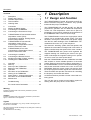
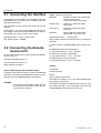
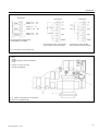
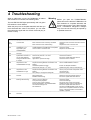
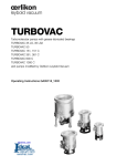
Vacuum Solutions
Application Support
Service
LEYBOLD VACUUM
GA 05.218/3.02
TURBOTRONIK
NT 340 M
NT 340 MA
NT 341 MA
Electronic frequency
converters
Cat.No.
857 29/30/31
857 32
857 34
Operating Instructions
Description
Contents
Description . . . . . . . .
Design and Function .
Standard Specification
Technical Data . . . . . .
Ordering Data . . . . . .
2
2.1
2.2
2.3
Connection . . . . . . . . . . . . . . . . . . . . . . . . . . 7
Setting the Mains Voltage . . . . . . . . . . . . . . . 7
Connecting the TURBOVAC . . . . . . . . . . . . . . 7
Connecting the Forevacuum Pump . . . . . . . . 7
2.4
TURBOTRONIK NT 340 M & MA without
temperature control (TCU):
Connecting the Cooling, Venting Device
and the Flange Heater . . . . . . . . . . . . . . . . . 8
TURBOTRONIK NT 340 MA with
temperature control (TCU):
Connecting the Temperature Control
and the Forevacuum Valve . . . . . . . . . . . . . . 10
TURBOTRONIK NT 341 MA:
Connecting the Temperature Control
and the Forevacuum Valve . . . . . . . . . . . . . . 12
2.5
2.6
.
.
.
.
.
.
.
.
.
.
.
.
.
.
.
.
.
.
.
.
.
.
.
.
.
.
.
.
.
.
.
.
.
.
.
.
.
.
.
.
.
.
.
.
.
.
.
.
.
.
.
.
.
.
.
.
.
.
.
.
.
.
.
.
.
.
.
.
.
.
.
.
.
.
.
Page
...2
...2
...3
...5
...6
1
1.1
1.2
1.3
1.4
2.7
2.8
2.9
2.10
Connecting the Interface . . . . . . . . . . . . . . . 14
Connecting the Remote Control . . . . . . . . . . 14
Modifying the Relay “Failure” (Option) . . . . . 16
Installing the TURBOTRONIK . . . . . . . . . . . 16
3
3.1
3.2
3.3
3.4
3.5
3.6
3.7
3.8
3.9
Operation . . . . . . . . . . . . . . . . . . . . . . . . . . 18
Start-up . . . . . . . . . . . . . . . . . . . . . . . . . . . . 18
Start-up of the TURBOVAC . . . . . . . . . . . . . 18
Bakeout of the TURBOVAC . . . . . . . . . . . . . 18
Operation . . . . . . . . . . . . . . . . . . . . . . . . . . 19
Shut-down of the TURBOVAC . . . . . . . . . . . 19
Venting of the TURBOVAC . . . . . . . . . . . . . . 19
Power Failure - Linecord Interruption . . . . . . 19
Shut-down of the TURBOTRONIK . . . . . . . . 20
Maintenance . . . . . . . . . . . . . . . . . . . . . . . . 20
4
Troubleshooting . . . . . . . . . . . . . . . . . . . . . . 21
1 Description
1.1 Design and Function
The TURBOTRONIK NT 340 M, NT 340 MA, and NT 341
MA are electronic frequency converters. They operate
turbomolecular pumps TURBOVAC.
The TURBOTRONIK NT 340 MA and NT 341 MA are
prepared for operation with an additional temperature
control unit. This temperature control unit is part of a
temperature control which maintains the temperature of
the TURBOVAC within a narrow control range.
The TURBOTRONIK converts the single-phase mains
voltage into a regulated DC power supply. The unit’s
electronic circuitry then switches this DC power supply
onto the four stator windings of the TURBOVAC’s commutatorless DC motor in a cyclical sequence.
This electronic switching system uses Hall probes, and
replaces the commutator normally found in DC motors. A
digital controller keeps the speed of the motor constant.
The TURBOTRONIK also powers and regulates the
magnetic bearing unit. Switching the motor to the generator mode keeps the magnetic bearing unit in operation even in case of a mains power failure.
Both the TURBOTRONIK and the TURBOVAC are fitted
with sensors to ensure reliable operation of the entire
system. External control and monitoring equipment e.g.
the LEYBOTRONIK I can be connected via floating plugand-socket terminals located at the rear of the TURBOTRONIK. Both the remote control unit and the lines
for the pump system’s status signals are connected here.
These terminals also provide connections for controlling
the forepump, the heater and valves.
An RS-232 interface provides a further control and monitoring option.
The unit also has a counter-current braking system for
slowing down the pump when it is shut down.
EC Conformance Declaration . . . . . . . . . . . . 22
Warning
Indicates procedures that must be strictly observed to prevent
hazards to persons.
Caution
Indicates procedures that must be strictly observed to prevent dam
age to, or destruction of the appliance.
Figures
The references to diagrams, e. g. (2/10), consist of the Fig. No. and
the Item No. in that order.
We reserve the right to alter the design or any data given in these Op
erating Instructions.
The illustrations are not binding.
2
GA 05.218/3.02 - 11/97
Description
1.2 Standard Specifications
TURBOTRONIK NT 340 M
Mains voltage
setting
230 V
120 V
Cat. No.
857 29
857 30
for TURBOVAC
340 M, MC, 400 MC
Standard Specification
Power linecord, Miniature fuses: 2 T 8.0 A; 2 T 4.0 A;
2 T* 3.15 A; 2 T1.0 A; 2 T 0.5 A; 2 T 0.315 A
3 mains plugs, 2 terminal strips,
1 portable socket-outlet
Mains voltage
setting
100 V
Cat. No.
857 31
for TURBOVAC
340 M, MC, 400 MC
Standard Specification
Power linecord, Miniature fuses: 2 T 4.0 A;
2 T 3.15 A; 2 T1.0 A; 2 T 0.5 A; 2 T 0.315 A
3 mains plugs, 2 terminal strips,
1 portable socket-outlet
TURBOTRONIK NT 340 MA
Mains voltage
setting
120 V
Cat. No.
857 32
for TURBOVAC
340 M, 340 MC
340 MCT
400 MC, 400 MCT
Standard Specification
Power linecord, Miniature fuses: 2 T 8.0 A; 2 T 0.5 A;
TURBOTRONIK NT 341 MA
Mains voltage
setting
208 V
Cat. No.
857 34
for TURBOVAC
341 MCT, 410 MCT
Standard Specification
Power linecord (mounted),
Miniature fuses 4 T 5.0 A, 2 T 0.5 A
Connection lines to the TURBOVAC do not belong to
the standard specifications.
*T= slow-blow
GA 05.218/3.02 - 11/97
Fig. 1 Front panels of the TURBOTRONIK,
explanation see table 1 and 2
3
Description
Table 1: Operational Status Display of the Front Panel LEDs
LED
Color
Display
LOAD
(LED chain)
green
LED “START” lights up: speed of the TURBOVAC (individual LED, linear display)
LED “STOP” lights up: speed of the TURBOVAC (individual LED, linear display)
LED “OVERLOAD” lights up: speed of the TURBOVAC (individual LED, linear display)
LED “NORMAL” lights up: motor current (LED chain, logarithmic display)
LED “FAILURE” lights up: failure code (one LED “LOAD” flashes)
REMOTE
yellow
Lights up when the converter is controlled via the remote control inputs or via the interface;
key manipulation is ignored.
Flashes when control is possible both via keyboard and the RS 232 interface.
POWER
green
Lights when mains power supply is on.
NORMAL
green
Lights during normal operation, speed is above 95 % of the target speed
Flashes in case of acceleration, braking and “OVERLOAD”.
FAILURE
red
Lights in case of failure.
Flickers in case of current peaks within the magnetic bearings.
HEATING
only on NT 340 M
green
Lights when heating is on.
Flashes when heating has been preselected.
HIGH SPEED
only on NT 340 MA
and NT 341 MA
green
Lights when the TURBOVAC runs with high speed (51,600 min-1).
OVERLOAD
yellow
Lights in case of overload, i. e. speed is below 95 % of the target speed having finished
the acceleration sequence.
START
green
Lights in case of TURBOVAC’s acceleration.
Flashes when the delay start-up time is active.
STOP
green
Lights when the TURBOVAC brakes.
Table 2: Functions of the Front Panel Keys
Key
Functions
HEATING
only on NT 340 M
Switching the TURBOVAC’s heating on and off.
HIGH SPEED
only on NT 340 MA
and NT 341 MA
Selecting high or optimized speed for TURBOVAC.
see Section 3.1.
START
Starting the TURBOVAC’s acceleration.
STOP
Braking the TURBOVAC.
Resetting a failure report.
4
GA 05.218/3.02 - 11/97
Description
1.3 Technical Data
Supply Outlets NT 340 M & MA
50/60 Hz
Voltage value corresponds to mains voltage
VALVE
max. 20 VA
HEATER
max. 300 VA
FAN
max. 100 VA
<1000 VA
For 100 V and 120 V connection: sum of the supply outlets (VALVE, HEATER, FAN)
max. 400 VA
Mains voltage, with selector switch
100/120/220/240 V,+10%/-15%
Mains frequency
Power consumption
including all connected units
Power consumption of theTURBOVAC
Rated speed of the TURBOVAC
<400 VA
43,860 / 51,600 min-1
6,000 min-1
Minimum speed of the TURBOVAC
Power output (motor)
Nominal voltage
Current limitation
50 V
7A
Power output for the magnetic bearing
Nominal voltage
Current limitation
± 16 V
±7A
RS 232/V.24
25-pin, D-shell, female
4,800 or 9,600
Operating temperature;
with sufficient free convection
0-45°C (32°F - 113°F)
Storage temperature
-25°C...+70°C (-77°F - +158°F)
Interference elemination
ISM appliance group 1, Limit value class A
according to EN 50081-2 / EN 55011
Control Inputs - digital, floating
each terminal
Interface
Connector
Baud rate
25 Veff AC max., 60 V DC
versus protective conductor
LEYBOTRONIK I compatible
Interference resistance
High level; between “+” and “-” terminal
13 V...33 V/max. 10 mA
Electrostatic discharge (ESD)
IEC 801-2, VDE 0843, Part 2
Low level; between “+” and “-” terminal
0 V...7 V
Burst IEC 801-4, VDE 0843, Part 4
Level III
Pulse duration
for remote control active “START” pump,
“STOP” pump, heater On/Off
>200 ms
high-energy impulse
IEC 801-5, VDE 0843, Part 5
Level III
Target speed analog input, not isolated
Setting range
Rated Speed
Minimum Speed
Weight
0...10 V
0V
10 V
Control Outputs
Relay
25 Veff AC, 60 V DC, 2 A/60 W/125 VA
for normal operation
operating contact
for acceleration
operating contact
for failure
resting contact, switchable
to operating contact
Severity 4
approx. 7 kg
Temperature control unit: supply outlets
Voltage corresponds to mains voltage
Heating collar “HEATER”
max. 120 W
Cooling water magnetic valve “COOLER”
max. 30 W
Forevacuum valve “VALVE”
max. 120 W
Temperature control unit: fuses
F1 and F2
F3
T 1.6 A
T 0.315 A
Analog voltage
0...10 V
selectionable speed or motor current proportional
Loadable
max. 5 mA
Standstill, no current
corresponds to 0 V
Rated speed, max. current
corresponds to 10 V
Reference voltage
15 V, max. 20 mA
(not isolated for speed potentiometer and remote
control inputs)
Forevacuum pump “FOREPUMP”;
Relay point
GA 05.218/3.02 - 11/97
6 A, 750 VA, 250 V
5
Description
(Front panel)
(Housing)
NT 340 M
(Front panel)
(Housing)
NT 340 MA
NT 341 MA similar
Fig. 2a Dimensional drawings of TURBOTRONIK , dimensions in mm
1.4 Ordering Data
Accessories for temperature control
Ref. No.
Pump system control LEYBOTRONIK I
Power unit for LEYBOTRONIK I
Delaying venting device
Venting valve for delaying venting device
013 10
upon request
012 44
012 45
TURBOTRONIK NT 340 M
Connection line set for connecting
the TURBOVAC
3 m long
5 m long
10 m long
20 m long
Connection line to the
TURBOVAC bearing, 3 m long
6
859 20
859 22
Connection lines
to the heater
to the cooling water magnet valve (COOLER)
to the valve
to the temperature control unit (I/O)
to the Pt 100
859
859
859
859
859
31
32
33
34
39
TURBOTRONIK NT 341 MA
857
857
857
857
70
71
72
73
Connection line to the
TURBOVAC motor, 20 m long
859 12
Connection line to the
TURBOVAC bearing, 20 m long
859 13
Accessories for temperature control
TURBOTRONIK NT 340 MA
Connection line to the
TURBOVAC motor, 3 m long
Temperature control unit (TCU)
Temperature sensor Pt 100
859 10
859 11
Temperature control unit (TCU)
Temperature sensor Pt 100
859 21
859 22
Connection lines
to the valve
to the temperature control unit (I/O)
mains connection line to the temperature
control unit
to the Pt 100
to the cooling water magnet valve (COOLER)
859 33
859 34
859 35
859 36
859 37
GA 05.218/3.02 - 11/97
Connection
(Front panel)
(Housing)
NT 340 MA with
plugged-in temperature
control unit
Fig. 2b Dimensional drawings of TURBOTRONIK , dimensions in mm
2 Connection
Warning
Connections for forevacuum pump, cooling,
venting valve and flange heater must be
done by a qualified electrician in accordance with the applicable safety regulations.
2.1 Setting the Mains
Voltage
The TURBOTRONIK has been set at the factory for a
mains power supply; see Section „1.2 Standard Specification“.
To change this setting, remove the dummy plug (3/15)
with a screwdriver and reinsert it according to the stamped-on voltage setting. The selected voltage indication
must be in the immediate proximity of the arrow.
If you do change the voltage setting, please also change
the line power fuse accordingly; see the table.
Fuses
LINE
VALVE
HEATING FAN
————————————————————————
100 V
T*) 4.0 A T 0.315 A T 3.15 A
T 1.0 A
120 V
T 8.0 A T 0.315 A T 3.15 A
T 1.0 A
220/240 V T 4.0 A T 0.315 A T 3.15 A
T 1.0 A
2.2 Connecting the
TURBOVAC
Insert and fasten the connection line to the motor of the
TURBOVAC at the socket DRIVE and to the TURBOVAC
itself.
Insert and fasten the connection line to the stabilizer and
axial sensor of the TURBOVAC at the socket BEARING
and to the TURBOVAC itself; both plugs are non-interchangeable.
2.3 Connecting the
Forevacuum Pump
Connect the forepump to the relay contact output FOREPUMP. When pressing the START key the contact is
closed without any delay and the forepump is switched
on.
The forepump is shut down when the TURBOVAC has
come to a standstill, switching examples see fig. 11.
A starting delay for the TURBOVAC can be set at the
potentiometer DELAY; see Section 3.1
(*) slow-blow)
In case of need, other fuses may be installed for VALVE,
HEATING and FAN. However, the sum of the fuses’
capacity for the three connections must not exceed:
4.5 A for 100/120 V
6.0 A for 220/240 V.
Plug the power linecord into the socket (3/14), (5/15).
The NT 341 MT has a fixed linecord.
GA 05.218/3.02 - 11/97
7
Connection
Key to Fig. 3
1
Power switch
2
Relay contact for forevacuum pump
ON/OFF
3
Connection for supply of the
TURBOVAC
4
LED red, magnetic bearing active
5
Connection for the magnetic bearing
of the TURBOVAC
6
Connection socket for RS 232 interface
7
Connection terminal strip
8
Potentiometer for setting
the delay time
9
Parameter selection for RS 232
interface
10 Connection for fan or solenoid valve
for water cooling
11 Connection for heating
12 Fuses
13 Connection for venting valve
14 Connection for power linecord
15 Plug for selecting the mains
voltages with integrated fuse
Fig. 3 TURBOTRONIK NT 340 M & MA, rear panel
2.4 NT 340 M & NT 340 MA without temperature control:
Connecting the Cooling, Venting Device and the Flange
Heater
Cooling
The mains power supply to the socket (3/10) is switched
on as soon as the TURBOVAC acceleration sequence
begins; max. load 100 VA. The relevant fuse (3/12) is
below the socket.
The power supply to the socket is switched off once the
TURBOVAC has come to a standstill and when the
power switch is turned off.
A magnetic valve for the water cooling or a fan can be
connected to the socket (3/10).
Venting
The mains power supply to the socket (3/13) is switched
on without any delay when START is activated. The
power is turned off when STOP or FAILURE are activated; max. load 20 VA. The relevant fuse (3/12) is below
the socket.
8
Caution
Any interruption in power, no matter how
short, will cause the pump to be vented.
Power Failure Airing Valve
If the TURBOVAC is operated without purge gas a power
failure airing valve can be connected to socket (3/13)
VALVE.
Purge Gas- and Venting Valve
When operating the TURBOVAC with purge gas it must
be vented via the purge gas and venting valve.
Delayed Venting Device and Venting Valve
When shutting down or in case of a power failure the
connection of the delayed venting device allows for setting the start and duration of the venting sequence in
order to protect a system or a process-procedure.
The presetting time can vary between 3 to 15 minutes.
A short power failure does not entail an unwanted venting.
Connect the delayed venting device to (3/13).
GA 05.218/3.02 - 11/97
Connection
HEATER
VALVE
N2
DRIVE
BEARING
FOREPUMP
POWER
FAN (COOLER)
Fig. 4 Block wiring diagram for TURBOVAC 340 M & MC & 400 MC and NT 340 M & MA
Flange Heater
(Only for pumps with CF connection flange)
The mains power supply to the socket (3/11) is switched
on when HEATING is activated, provided that the pump
operation status is NORMAL; max load 300 VA.
The relevant fuse (3/12) is below the socket.
Connect the flange heater to the TURBOVAC at socket
(3/11) “HEATER”.
GA 05.218/3.02 - 11/97
9
Connection
Key to fig. 5
1 Power switch
2 Relay contact for forevacuum
pump ON/OFF
3 Connection for supply of the
TURBOVAC
4 LED red, magnetic bearing
active
5 Connection for the magnetic
bearing of the TURBOVAC
6 Connection socket for RS 232
interface
7 Connection terminal strip
8 Potentiometer for setting
the delay time
9 Parameter selection for RS 232
interface
10 Connection for voltage supply of
the temperature controller
11 Connection for cooling water
magnetic valve
12 Connection for heating collar
13 Connection for forevacuum valve
14 Connection for Pt 100
15 Connection of the power linecord
Fig. 5 TURBOTRONIK NT 340 MA with temperature control unit, rear panel
Warning
Prior to opening the temperature control unit
pull it off. If the plug of the temperature control
unit is connected there may be line voltage
inside the unit.
Fig. 6 Location of the fuses F1, F2, F3 in the temperature control unit;
bottom removed
Table 3: Temperature Control Unit: Pin assignment of the Sub D Sockets
Sub D Socket VOLTAGE I/0 (Plug)
Sub D Socket Pt 100 (Socket)
Pin 1
Relay contact*
Linked with pin 2
Pin 2
Voltage of the Pt 100 (0.1 V corresponds to 1 °C)
Pt 100
Pin 3
Common point for the relay*
Pt 100
Pin 4
Voltage treshold „NORMAL“
Linked with pin 3
Pin 5
Relay contact*
Linked with pin 3
Pin 6
Earthed (of NT: pin 21 of the socket REMOTE)
Linked with pin 2
Pin 7
Voltage treshold „Pump too cold“
Linked with pin 3
Pin 8
Voltage treshold „Pump too hot“
Linked with pin 3
Pin 9
+ 15 V (of NT: pin 210 of the socket REMOTE)
Voltage supply for temperature controller
Linked with pin 3
* If the pump is too hot or too cold (FAILURE), the contact between pin 1 and 3 is closed and open between pin 3 and 5.
In the operation mode NORMAL of the temperature controller the contact between pin 1 and 3 is open and closed between pin 3 and 5.
Too hot: T > 75 °C (167°F); too cold: T < 55 °C (131°F); NORMAL: 55 °C ≤ T ≤ 75 °C (131°F ≤ T ≤ 167°F)
10
GA 05.218/3.02 - 11/97
Connection
HEATER
DRIVE
N2
BEARING
FOREPUMP
TCU
POWER
COOLER
VALVE
Pt 100
Fig. 7 Block wiring diagram for TURBOVAC 340 MCT & 400 MCT and NT 340 MA with temperature control
2.5 NT 340 MA with temperature
control: Connecting the
Temperature Control and the
Forevacuum Valve
Forevacuum valve
The socket VALVE is supplied with current provided the
mains voltage is applied, max. rate: 120 W.
A heater for a forevacuum valve can be connected to the
socket.
Temperature control
The parts required for temperature control are listed in
Section 1.4.
Plug in the temperature control unit, see Fig. 5.
The temperature control controls the temperature of the
TURBOVAC 340 MCT & 400 MCT within a narrow control range.
Connect the connection line to the heating collar at the
heating collar of the TURBOVAC and at the socket HEATER.
Plug in the connection line to the cooling water magnetic
valve at the cooling water magnetic valve of the TURBOVAC and at the socket COOLER.
Plug the connection line of the Pt 100 of the TURBOVAC
into the socket Pt 100.
Plug in the connection line temperature control unit TURBOTRONIK at the sockets VOLTAGE I/O and
REMOTE.
GA 05.218/3.02 - 11/97
11
Connection
Key to Fig. 8
1
Power switch
2
Relay contact for forevacuum
pump ON/OFF
3
Connection for supply of the
TURBOVAC
4
LED red, magnetic bearing active
5
Connection for the magnetic
bearing of the TURBOVAC
6
Connection socket for RS 232
interface
7
Connection terminal strip
8
Potentiometer for setting
the delay time
9
Parameter selection for RS 232
interface
10 Power linecord
11 Fuses power supply
Fig. 8 TURBOTRONIK NT 341 MA, rear panel
2.6 NT 341 MA:
Connecting the Temperature Control and the
Forevacuum Valve
Temperature control
The parts required for temperature control are listed in
Section 1.4.
Connect the connection line of the heating collar at the
socket HEATER.
Plug in the connection line to the cooling water magnetic
valve at the cooling water magnetic valve of the TURBOVAC and at the socket COOLER.
Plug the connection line of the Pt 100 of the TURBOVAC
into the socket Pt100.
Plug in the connection line temperature control unit TURBOTRONIK at the sockets VOLTAGE I/O and
REMOTE.
Install the temperature control unit.
The temperature control controls the temperature of the
TURBOVAC 341 MCT & 410 MCT within a narrow control range.
The temperature control unit has to be connected to 120
V AC mains voltage.
Warning
Forevacuum valve
The socket VALVE is supplied with current provided the
mains voltage is applied, max. rate: 120 W.
A heater for a forevacuum valve can be connected to the
socket.
The power supply must ensure that even in
case of failure no lethal voltages may occur.
12
GA 05.218/3.02 - 11/97
Connection
HEATER
DRIVE
N2
BEARING
FOREPUMP
POWER
VALVE
POWER
TCU
COOLER
Pt 100
Fig. 9 Block wiring diagram for TURBOVAC 341 MCT & 410 MCT and NT 341 MA with temperature control
COOLER
HEATER
VALVE
POWER
SUPPLY
4,4
60
7,6
31,8
25,5
VOLTAGE I/O
Pt 100
127
138,5
Fig. 10 Temperature Control Unit, dimensions in mm
GA 05.218/3.02 - 11/97
13
Connection
2.7 Connecting the Interface
Inputs - Remote control active
REMOTE
Disables the keys and activates the
remote control inputs
(continuous signal; High-active)
START pump
Impulse or continuous signal;
High-active
STOP pump
At DIP switch 1 you can choose whether the analog output voltage at the terminal strip REMOTE will rise proportionnally to the motor current or the speed.
Impulse or continuous signal;
Low-active
HEATING
Heating ON/OFF steady-state
signal; High = On, Low = Off
ON analog output = motor current LOAD.
Speed (target value)
OFF analog output = SPEED.
Due to safety reasons the STOP function (Low-active) is
dominant.
A description of the interface for operating the TURBOTRONIK with a computer can be ordered under the
description SB 05.207.
The parameters for the interface will be set at the DIP
switches.
2.8 Connecting the Remote
Control Unit
analog signal
In order to start the TURBOTRONIK via the remote control:
the REMOTE-inputs must be activated
i.e. high-level between “+” and “-” terminal,
For the signal assignments of the terminal strip REMOTE refer to fig. 12.
the STOP-inputs must be inactivated
i.e. high-level between “+” and “-” terminal,
Switching examples see fig. 13.
the START-inputs must be activated
i.e. high-level between “+” and “-” terminal.
Technical Data see section 1.3.
Relay statuses see table 4.
Note for Switching Example ON/OFF Switch
If instead of the ON-OFF switch a jumper is established
between Pin 4 and 20, the TURBOVAC will start up automatically once the TURBOTRONIK is switched on.
Acceleration,
Normal operation,
Failure,
Current-/speed actual value,
The reference voltage is +15 V for speed potentiometer
and remote control inputs.
Caution
The maximum permissible voltage at each
of the terminals is 25 Veff AC, 60 V DC versus protective conductor.
14
Outputs
The reference voltage is protected by the fuse F7. Position of the fuse se fig. 14. For changing the fuse open the
TURBOTRONIK as described in section 2.9.
GA 05.218/3.02 - 11/97
Connection
Power <750 VA /single-phase
Power >750 VA /single-phase
three-phase
Fig. 11 Switching examples for the motor connection of the forevacuum pump
Key to Fig. 6
Inputs
Inputs
Outputs
L=LOW; H=HIGH
13
14
15
16
17
18
19
20
21
22
1
2
3
4
5
6
7
8
9
10
11
12
Outputs
REMOTE
REMOTE
“STOP”
“STOP”
not used
not used
“START”
“START”
HEATING
HEATING
not used
not used
“-”
“+”
“-”
“+”
“-”
“+”
“-”
“+”
H=active
L=active
H=active
H=active
NORMAL
Target speed
NORMAL
attained
FAILURE
FAILURE
Acceleration (ACCEL)
Acceleration (ACCEL)
not used
+15 V
earthed
Analog output voltage
0...10 V
23 earthed
24 Speed target value, 10...0 V
The inputs are
opto-coupled
Fig. 12 TURBOTRONIK rear panel;
assigment of the terminal strip REMOTE
Table 4
Relay status
VALVE
(3/13)
HEATER
(3/11)
FAN
(3/10)
FOREPUMP
(3/2)
ACCEL
Fig. 12
FAILURE
Fig. 12
NORMAL
Fig. 12
Power off
open
open
open
open
open
closed**
open
Standstill
open
open
open
open
open
closed**
open
Delayed start-up device
closed
open
open
closed
closed
closed**
open
Acceleration
closed
open
closed
closed
closed
closed**
open
NORMAL
closed
closed*
closed
closed
open
closed**
closed
Overload
closed
closed*
closed
closed
open
closed**
closed
Braking
open
open
closed
closed
open
closed**
open
Failure; TURBOVAC rotates
open
open
closed
closed
open
open**
open
Failure; TURBOVAC stands still
open
open
open
open
open
open**
open
* if selected
** modifications possible
GA 05.218/3.02 - 11/97
15
Connection
2.9 Modifying the Relay
FAILURE (Option)
2.10 Installing the
TURBOTRONIK
On delivery the relay FAILURE is a resting contact (normally closed). It can be changed to an operating contact
(normally open).
Install the TURBOTRONIK.
Warning
Before you open the TURBOTRONIK
please first ensure that the TURBOVAC has
been braked to a complete standstill, and
that the mains power cord is disconnected.
Since, nonetheless dangerous voltages
may occur the unit must only be opened by
a qualified electrician.
The heat dissipation of the TURBOTRONIK must not be
obstructed. Insure a sufficient ventilation - the ambient
temperature during operation must not exceed 45°C
(113°F).
If - after installation - the rear of the TURBOTRONIK
is no more accessible, switch on the POWER switch
before mounting and if nec. set the starting delay; refer to
section 3.1.
Warning
If the TURBOTRONIK is built into a rack the
mains plug is not within easy reach. Therefore install a separation between the TURBOTRONIK and the mains when you build it
into a rack.
For modifying the relays, remove the fastening screw of
the upper cover sheet at the rear and pull out the upper
cover sheet.
Modify the jumper (14/2).
State of delivery
Modification
Warning
resting contact 1-2
operating contact 2-3
Close the TURBOTRONIK again.
We recommend noting all the modifications made on the
unit itself or at least in the Operating Instructions for that
particular instrument.
16
Do not operate the TURBOTRONIK with the
standard mains lead in chemically aggressive surroundings. If you operate the TURBOTRONIK in chemically aggressive surroundings replace the mains lead by a resistant one.
GA 05.218/3.02 - 11/97
Connection
Terminals No.
Terminals No.
Terminals No.
active = 13 V ... 33 V
inactive = 0 V ... 7 V
active = 0 V ... 7 V
inactive = 13 V ... 33 V
active = 13 V ... 33 V
inactive = 0 V ... 7 V
Active control with a voltage signal;
LEYBOTRONIK I compatible
Via continuous contact, remote control
via key; passive control with contacts
Via continuous contact, ON/OFF
switch; passive control with contacts
Fig. 13 Connection of the remote control
Key to Fig. 14
1 Relay
2 Jumper
3 Connection plug for the RS 232 interface
4 Fuses
F7 Fuse for 15 V at Pin 20 of the
terminal strip REMOTE
Fig. 14 Position of the jumper for the relay failure;
top view into the TURBOTRONIK
GA 05.218/3.02 - 11/97
17
Operation
3 Operation
3.1 Start-up
Insert the power plug.
Switch on the POWER switch.
Having switched on the power switch the TURBOVAC’s
stabilizer is activated and the rotor lifts up.
Afterwards all LEDs light up for approx. 2 s for a functional check. The green LED „POWER“ remains on.
On the TURBOTRONIK NT 340 MA and 341 MA with
temperature control the temperature control is switched
on.
It is not necessary to check or to recalibrate the rotor
position control system.
Setting the Start-up Delay
You can set a start-up delay for the TURBOVAC of up to
five minutes at the rear of the TURBOTRONIC at DELAY.
Due to the starting delay the TURBOVAC starts after the
forevacuum pump.
Selecting high or optimized speed
(only on NT 340 MA & NT 341 MA)
The TURBOVAC is designed for operation with optimized
speed.
In certain cases the standard speed which is set on delivery, can be increased (HIGH SPEED). Please contact
your local Leybold service representative.
Caution
HIGH SPEED operation may result in shorter operational lifetime of the pump. Your
warranty may be voided.
3.2 Start-up of the
TURBOVAC
Pressing the START key initiates the acceleration
sequence; if a forevacuum pump is connected it will start
up immediately.
If a delay has been set, the START LED will flash during
the delay period, after which it will remain on con
tinuously and the TURBOVAC starts.
The NORMAL LED flashes during acceleration. The LED
chain indicates the increasing speed with one LED each.
When 95% of the target speed has been reached, the
LED NORMAL remains on continuously, the START LED
extinguishes.
During normal operation the LED chain indicates the
course of the increasing motor power consumption; the
increasing current (load) drawn by the TURBOVAC is
indicated by the LED chain with one LED each lighting
up after the other starting at the bottom and moving
upwards.
If the TURBOVAC exceeds the minimum speed within 8
minutes but does not attain 95 % of the target speed it
will change to OVERLOAD operation.
The LED OVERLOAD lights up and the LED chain indicates the speed.
3.3 Bake-out of the
TURBOVAC
(only for NT 340 M)
Bake-out is only possible with the CF version during
NORMAL operation.
Pressing the HEATING key switches the flange heater
ON and OFF. The green LED in the key lights up when
the heating is ON.
With preselection the LED flashes during the accelera
tion phase; during NORMAL and activated heating the
LED lights continuously.
18
GA 05.218/3.02 - 11/97
Operation
3.4 Operation
During normal operation the TURBOVAC runs with target
speed. The LED NORMAL lights and the LED chain
shows - starting at the bottom and moving upwards the current consumed.
In case of increased load (e.g. increased pressure due to
a leak) the speed is compensated via an additional current consumption. Thus, the number of the lighting LEDs
is a measure of the pressure rise.
A further pressure rise beyond the point of the max. current limitation leads to a decreasing speed due to an
increasing gas friction.
3.6 Venting of the
TURBOVAC
Vent the TURBOVAC every time the TURBOVAC is
switched off in order to prevent a potential backstreaming of oil vapors from the forevacuum line to the highvacuum side.
If a power failure airing valve or a delayed venting
device is connected to the socket (3/13) VALVE the TURBOTRONIK controls venting automatically.
The speed will likewise drop when the temperature of the
TURBOVAC or TURBOTRONIK is too high, the LED
OVERLOAD lights up.
3.7 Power Failure Linecord Interruption
If the target speed drops below 95% the LED chain indicates the speed. The LED NORMAL flashes.
If there is a power failure or if the power plug is
accidentally disconnected, the TURBOTRONIK automatically switches over the drive of the TURBOVAC to generator operation. This means that during run-down of the
pump, the active magnetic bearing regulation will be
maintained until the rotor sets down on the touch-down
bearings with the rate of rotation being low.
If the speed drops below the minimum speed, the TURBOVAC is switched off and the LED FAILURE lights up.
3.5 Shut-down of the
TURBOVAC
Pressing the STOP key switches off the pump and the
heater and activates braking.
The forevacuum pump will be switched off provided it is
connected via FOREPUMP; the TURBOVAC will be vented if the venting valve is connected via (3/13).
The LED in the STOP key lights up, and the LED NORMAL flashes until the TURBOVAC stands still.
The motor brakes the pump actively until it comes to a
complete standstill; the speed is again indicated by the
LED chain.
If the connecting lines between the TURBOVAC and the
TURBOTRONIK are interrupted, the automatic generator operation and the emergency power supply to the
active magnetic bearing are put out of operation. In this
case, the rotor is set down immediately onto the touchdown bearings, runs down with a considerable noise
level and there is a risk that the touch-down bearings are
damaged.
The connection line to the TURBOTRONIK is secured
against accidental interruption. If it is, nevertheless, interrupted e. g. by mechanical destruction, brake the TURBOVAC via venting until it stands still.
If a malfunction occurs the FAILURE signal can be reset
via the STOP key provided the cause of malfunction has
been eliminated and the rotor of the TURBOVAC stands
still.
GA 05.218/3.02 - 11/97
19
Operation
3.8 Shutdown of the
TURBOTRONIK
Press the STOP key, and wait until the pump comes to a
standstill.
The LEDs in the keys START, STOP and NORMAL are
extinguished.
Switch the POWER switch to the “0” position. The temperature control at the TURBOTRONIK NT 340 MA and
NT 341 MA with temperature control is switched off.
If the red LED DON’T DISCONNECT has gone off the
connection lines to the TURBOVAC can be disconnected
in case of necessity.
Caution
Only after the pump has come to a standstill
is the POWER switch to be switched to the
“0” positon.
In case of accidental shutdown, start up the pump at
once.
3.9 Maintenance
The TURBOTRONIK is maintenance-free.
20
GA 05.218/3.02 - 11/97
Troubleshooting
4 Troubleshooting
When a malfunction occurs, the TURBOVAC is braked
and the failure is indicated; see following table.
The red LED FAILURE lights permanently and one green
LED within the chain flashes.
When the pump is at a complete standstill, and after you
have eliminated the cause of the failure, you can reset
the malfunction signal with the STOP command (key or
remote control).
Warning
Before you open the TURBOTRONIK,
please first ensure that the TURBOVAC has
been braked to a complete standstill, and
that the mains power cord is disconnected.
Since, nonetheless dangerous voltages
may occur the unit must only be opened by
a qualified electrician.
LED flashes Symptom
Probable Cause
Recommended Corrective Action
————————————————————————————————————————————————————————————————
No. 1
Linecord fault.
Motor connection line incorrectly connected.
Check the motor connection line and connect it
(below)
correctly.
Motor connection line malfunctioning.
Replace the motor connection line.
————————————————————————————————————————————————————————————————
No. 2
TURBOVAC is not
TURBOTRONIK and TURBOVAC incompatible. Check the system.
supported by the
Loose contact in connection line.
Repair the connection lines.
TURBOTRONIK.
————————————————————————————————————————————————————————————————
No. 3
Not used
————————————————————————————————————————————————————————————————
No. 4
Speed below minimum or
Forevacuum pressure >10-2 mbar.
Check the forevacuum.
has not been attained
Pump blocked.
Inform the Leybold after-sales service.
during acceleration within
High-vacuum pressure too high.
Check the vacuum chamber.
8 minutes.
————————————————————————————————————————————————————————————————
No. 5
Temperature in the
Frequent switching between acceleration and
Let the TURBOTRONIK cool down.
TURBOTRONIK too high.
braking.
Ambient temperature too high.
Ensure an adequate ventilation.
Forevacuum pressure >10-2 mbar.
Operate the pump under normal load only.
————————————————————————————————————————————————————————————————
No. 6
Temperature in the
Frequent switching between acceleration and
Let the pump cool down and operate under
TURBOVAC too high.
braking.
normal load only.
Poor cooling or cooling line interrupted.
Check the cooling.
————————————————————————————————————————————————————————————————
No. 7
Self test.
Mains malfunction.
Switch the mains off and then again on.
EPROM malfunctioning.
Inform the Leybold after-sales service.
————————————————————————————————————————————————————————————————
No. 8
Bearing malfunctioning.
Venting curve not observed.
Check the system.
Pump incorrectly adjusted.
Control the bearings.
Pump or pump system vibration.
Set up the pump system more quietly.
Excess temperature in the TURBOTRONIK.
Operate the pump under normal load only.
Touch-down bearings worn.
Inform the Leybold after-sales service.
RF interference.
Ground the TURBOTRONIK, locate the AC
power cord in a separate bundle from the RF
source, change the location of the TURBOTRONIK, if needed.
————————————————————————————————————————————————————————————————
No. 9
Not used.
GA 05.218/3.02 - 11/97
21
EC Conformance Declaration
•
EC Low-Voltage Guidelines (73/23/EEC)
•
EEC Directive on Elektromagnetic Compatibility
(89/336/EWG), measured with a typical test
configuration
Applicable, harmonized standards:
•
EN 61010-1: 1993
Designation of the product:
•
EN 50081-2: 1992
Electronic frequency converter
•
prEN 50082-2: 1992
Catalog numbers:
857 29/30/31
857 32
857 34
Applied national standards and technical
specifications:
•
VDE 0411 Part 1/03.94
•
VDE 0839 Part 81-2/03.93
•
EVDE 0839 Part 82-2/01.93
LV.GT.0114.02.07.96
Models: TURBOTRONIK NT 340 M
NT 340 MA
NT 341 MA
Cologne, July 5, 1996
—————————————————————
Mr. Beeck, Instruments Division Manager
—————————————————————
Mr. Finke, Instruments Development
1.80.7.635.27 RSP 11.97
Cologne, July 5, 1996
Technical alterations reserved
This declaration becomes invalid if modifications are
made to the product without consultation with us.
The products comply with the following guidelines:
Printed in Germany on chlorine-free bleached paper
We, the Leybold Vacuum GmbH, declare herewith that
the products listed below, on the basis of their design
and engineering as well as in the embodiment which we
have placed on the market, comply with the applicable
safety and health requirements set forth in EC guidelines.
LEYBOLD VAKUUM GmbH
Bonner Strasse 498 (Bayenthal)
D-50968 Cologne
Tel.: + 49 (221) 347-0
Fax: + 49 (221) 347-1250
http://www.leyboldvac.de
e-mail:[email protected]
GA 05.218/3.02 - 11/97