1
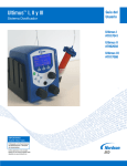
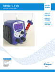
Ultimus™ I, II and III
Dispensing Workstation
User’s
Guide
Ultimus I
#7017041
Ultimus II
#7002003
Ultimus III
#7017068
IMPORTANT!
Save this Sheet.
Forward to
Maintenance or
Tool Crib Supervisors
Electronic pdf files of
EFD manuals are also available
at www.nordsonefd.com
EC Declaration of Conformity
In Accordance with EN ISO/IEC 17050-1:2010
Manufacturer:
Address:
Type of Equipment:
Product Name:
Model & Part Number:
Nordson EFD LLC
40 Catamore Boulevard
East Providence, RI 02914 USA
Fluid Dispenser
Ultimus™ I, II and III Series
❑Ultimus I, (2400) 7017041
❑Ultimus II, (2415) 7002003
❑Ultimus III, (2405) 7017068
Manufacture Date: ____________
Serial Number:
____________
The above listed product(s) have been evaluated for conformity to:
‘WEEE Directive’
2002/96/EC
‘RoHS Directive’
2011/65/EU
‘EMC Directive’
2004/108/EC
‘Low Voltage Directive’ 2006/95/EC
The standards to which conformity is declared are:
EN 55011, 2007
Industrial, scientific and medical (ISM) radio-frequency equipment Electromagnetic disturbance characteristics – Limits and methods
of measurement, Class A.
EN61000-3-2:2006/A1/A2(2009) Limits for Harmonic Current Emissions
EN61000-3-3:2008
Limitation of voltage changes, voltage fluctuations and flicker in public
low voltage supply systems
Emissions Standards:
EN61000-6-2:2005
Immunity Standards:
EN61000-4-2
EN61000-4-3
EN61000-4-4
EN61000-4-5
EN61000-4-6
EN61000-4-11
Electromagnetic compatibility (EMC) – Part 6-2: Generic standards – Immunity
for industrial environments.
Electrostatic Discharge (ESD)
Radiated RF Immunity
Electrical Fast Transient/Burst
Surge Immunity
Conducted RF Immunity
Voltage Dips, Short Interruptions
CAN/CSA-C22.2 No. 1010-1-92, ANSI/UL 61010A-1:2002, EN 61010-1:2001-02 Second Edition
Safety Requirements for Electrical Equipment for Measurement, Control, and Laboratory Use,
Part 1: General Requirements
Safety Standards:
Nordson EFD LLC
Danny Crane
Danny Crane
Plant Manager
Place: East Providence, RI USA
Date: May 18th, 2012
Authorized Representative:
European Technical Manager
EFD International
Unit 14, Apex Business Centre
Boscombe Road
Dunstable, Bedfordshire
LU5 4SB England
©2012 Nordson Corporation 7028764 Rev.01 v06/01/12
Introduction
Welcome to the Ultimus I, II and III, the most complete dispensing system on the market. This User’s
Guide will help you maximize the usefulness of your new workstation.
Please spend a few minutes to become familiar with the controls and features. Follow our recommended
testing procedures. Review the helpful information we have included, which is based on more than
30 years of industrial dispensing experience.
Most questions you will have are answered in this guide. However, if you need assistance, please do
not hesitate to contact Nordson EFD or your authorized Nordson EFD distributor.
In the USA, call 800.556.3484 between 8:30 a.m. and 5:30 p.m. Eastern time.
In Europe, call +44 (0) 1582 666334.
In Asia, call +86 (21) 3866 9006.
In all other areas, call your authorized EFD distributor or +1.401.431.7000.
The Nordson EFD Pledge
We pledge that you will be completely satisfied with our products. We endeavor to ensure that every
Nordson EFD product is produced to our no-compromise quality standards.
If you feel that you are not receiving all the support you require, or if you have any questions or
comments, I invite you to write or call me personally.
Our goal is to build not only the finest equipment and components, but also to build long-term customer
relationships founded on superb quality, service, value and trust.
Ken Forden, General Manager
2
www.nordsonefd.com [email protected] USA & Canada 800-556-3484 Europe +44 (0) 1582 666334 India+ 91 80 4021 3600 Asia +China: +86 (21) 3866 9006
Sales and service of Nordson EFD dispensing systems are available worldwide.
Contents
Safety . . . . . . . . . . . . . . . . . . . . . . . . . . . . . . . . . . . . . . . . . . . . . . . . . . . . . . . . . . . . . . 4
Getting Started . . . . . . . . . . . . . . . . . . . . . . . . . . . . . . . . . . . . . . . . . . . . . . . . . . . . . . . . 6
Specifications. . . . . . . . . . . . . . . . . . . . . . . . . . . . . . . . . . . . . . . . . . . . . . . . . . . . . . . . . 7
Features and Controls . . . . . . . . . . . . . . . . . . . . . . . . . . . . . . . . . . . . . . . . . . . . . . . . 8-10
Back Panel . . . . . . . . . . . . . . . . . . . . . . . . . . . . . . . . . . . . . . . . . . . . . . . . . . . . . . 11
Filling the Syringe Barrel . . . . . . . . . . . . . . . . . . . . . . . . . . . . . . . . . . . . . . . . . . . . . . . 13
Vacuum Control . . . . . . . . . . . . . . . . . . . . . . . . . . . . . . . . . . . . . . . . . . . . . . . . . . . . . . 14
Syringe Barrel Loaders . . . . . . . . . . . . . . . . . . . . . . . . . . . . . . . . . . . . . . . . . . . . . . . . . 15
Initial Test Procedures. . . . . . . . . . . . . . . . . . . . . . . . . . . . . . . . . . . . . . . . . . . . . . . . . . 16
Memory . . . . . . . . . . . . . . . . . . . . . . . . . . . . . . . . . . . . . . . . . . . . . . . . . . . . . . . . . . . . 18
Menu Functions . . . . . . . . . . . . . . . . . . . . . . . . . . . . . . . . . . . . . . . . . . . . . . . . . . . . . . 20
Input/Output Connection . . . . . . . . . . . . . . . . . . . . . . . . . . . . . . . . . . . . . . . . . . . . . . . . 22
Pin Function . . . . . . . . . . . . . . . . . . . . . . . . . . . . . . . . . . . . . . . . . . . . . . . . . . . . . . . . . 23
Vacuum Calibration. . . . . . . . . . . . . . . . . . . . . . . . . . . . . . . . . . . . . . . . . . . . . . . . . . . . 23
Troubleshooting . . . . . . . . . . . . . . . . . . . . . . . . . . . . . . . . . . . . . . . . . . . . . . . . . . . . . . 24
Helpful Hints. . . . . . . . . . . . . . . . . . . . . . . . . . . . . . . . . . . . . . . . . . . . . . . . . . . . . . . . . 25
Productivity Tools . . . . . . . . . . . . . . . . . . . . . . . . . . . . . . . . . . . . . . . . . . . . . . . . . . . . . 26
Warranty . . . . . . . . . . . . . . . . . . . . . . . . . . . . . . . . . . . . . . . . . . . . . . . . . . . . . Back Cover
IMPORTANT SAFETY INFORMATION
All Nordson EFD disposable components, including syringe barrels, cartridges, pistons, tip caps, end
caps, and dispense tips, are precision engineered for one-time use. Attempting to clean and re-use
components will compromise dispensing accuracy and may increase the risk of personal injury.
Always wear appropriate protective equipment and clothing suitable for your dispensing application.
Do not exceed maximum operating pressure of 100 psi (7.0kg/cm2).
Do not heat syringe barrels or cartridges to a temperature greater than 100°F (38°C).
Dispose of components according to local regulations after one-time use.
Do not clean components with strong solvents (e.g. MEK, Acetone, THF).
Cartridge retainer systems and barrel loaders should be cleaned with mild detergents only.
To prevent fluid waste, use Nordson EFD SmoothFlowTM pistons.
This manual is for the express and sole use of EFD dispenser purchasers
and users, and no portion of it may be reproduced in any form.
www.nordsonefd.com [email protected] USA & Canada 800-556-3484 Europe +44 (0) 1582 666334 India+ 91 80 4021 3600 Asia +China: +86 (21) 3866 9006
Sales and service of Nordson EFD dispensing systems are available worldwide.
3
Safety
Introduction
Read and follow these safety instructions. Task- and equipment-specific warnings, cautions and
instructions are included in equipment documentation where appropriate.
Qualified Personnel
Equipment owners are responsible for making sure that EFD equipment is installed, operated and
serviced by qualified personnel. Qualified personnel are those employees or contractors who are
trained to safely perform their assigned tasks. They are familiar with all relevant safety rules and
regulations, and are physically capable of performing their assigned tasks.
Intended Use
Use of EFD equipment in ways other than those described in the documentation supplied with the
equipment may result in injury to persons or damage to property.
Some examples of unintended use of equipment include
• Using incompatible materials
• Using incompatible or damaged parts
• Making unauthorized modifications
• Using unapproved auxiliary equipment
• Removing or bypassing safety guards or interlocks • Operating equipment in excess of maximum ratings
Regulations and Approvals
Make sure all equipment is rated and approved for the environment in which it is used. Any
approvals obtained for EFD equipment will be voided if instructions for installation, operation and
service are not followed.
Personal Safety
To prevent injury follow these instructions.
• Do not operate or service equipment unless you are qualified.
• Do not operate equipment unless safety guards, doors or covers are intact and automatic
interlocks are operating properly. Do not bypass or disarm any safety devices.
• If you receive even a slight electrical shock, shut down all electrical or equipment immediately.
Do not restart the equipment until the problem has been identified and corrected.
• Obtain and read Material Safety Data Sheets (MSDS) for all materials used. Follow the
manufacturer’s instructions for safe handling and use of materials, and use recommended
personal protection devices.
• To prevent injury, be aware of less-obvious dangers in the workplace that often cannot be
completely eliminated, such as hot surfaces, sharp edges, energized electrical circuits and moving
parts that cannot be enclosed or otherwise guarded for practical reasons.
• This equipment is for indoor use only.
• Use only the power adapter provided with the unit. Contact EFD to purchase a replacement adapter.
• Always keep dispensing end of syringe barrel pointed away from your face and towards the work
piece. Store the syringe barrel in an appropriate holder when not in use.
• Caution: Use EFD filter/muffler #7016875 or wear adequate ear protection when operating the
vacuum in close proximity for a prolonged period of time.
4
• Caution: A pressure regulator of 0 to 100 psi is intended to be provided before connecting unit
to the air supply.
Safety
Fire Safety
To avoid a fire or explosion, follow these instructions.
• Shut down all equipment immediately if you notice static sparking or arcing. Do not restart the
equipment until the cause has been identified and corrected.
• Do not smoke, weld, grind or use open flames where flammable materials are being used or stored.
• Provide adequate ventilation to prevent dangerous concentrations of volatile particles or vapors. Refer
to local codes or your material MSDS for guidance.
• Do not disconnect live electrical circuits when working with flammable materials. Shut off power at a
disconnect switch first to prevent sparking.
• Know where emergency stop buttons, shutoff valves and fire extinguishers are located.
• Clean, maintain, test and repair equipment according to the instructions in your equipment
documentation.
• Use only replacement parts that are designed for use with original equipment. Contact your EFD
representative for parts information and advice.
Action in the Event of a Malfunction
If a system or any equipment in a system malfunctions, shut off the system immediately and perform
the following steps:
• Disconnect and lock out system electrical power.
• Identify the reason for the malfunction and correct it before restarting the system.
Disposal
Dispose of equipment and materials used in operation and servicing according to local and national
codes.
RoHS标准相关声明 (China RoHS Hazardous Material Declaration)
产品名称
Part Name
金属转接头
有害物质及元素
Toxic or Hazardous Substances and Elements
铅
汞
镉
六价铬
多溴联苯
多溴联苯醚
Lead
Mercury
Cadmium
(Pb)
(Hg)
(Cd)
Hexavalent
Chromium
(Cr6)
Polybrominated
Biphenyls
(PBB)
Polybrominated
Diphenyl Ethers
(PBDE)
X
O
O
O
O
O
All Brass Fittings
O: 表示该产品所含有的危险成分或有害物质含量依照EIP-A, EIP-B, EIP-C 的标准低于
SJ/T11363-2006 限定要求。
O: Indicates that this toxic or hazardous substance contained in all the homogeneous materials for this part,
according to EIP-A, EIP-B, EIP-C is below the limit requirement in SJ/T11363-2006.
X: 表示该产品所含有的危险成分或有害物质含量依照EIP-A, EIP-B, EIP-C 的标准高于
SJ/T11363-2006 限定要求.
X: Indicates that this toxic or hazardous substance contained in all the homogeneous materials for this part,
according to EIP-A, EIP-B, EIP-C is above the limit requirement in SJ/T11363-2006.
www.nordsonefd.com [email protected] USA & Canada 800-556-3484 Europe +44 (0) 1582 666334 India+ 91 80 4021 3600 Asia +China: +86 (21) 3866 9006
Sales and service of Nordson EFD dispensing systems are available worldwide.
5
Getting
Started
The Ultimus workstation is designed to provide complete process control for precise, repeatable fluid
dispensing.
Key features include
•
All-digital, multi-function display with simultaneous readout of air pressure, time, vacuum,
deposit shot count and time of day
•
Unique air management reservoir and high-speed solenoid system for consistent, repeatable
deposits
•
Time increment adjustments as small as 0.0001 seconds for precise deposit control
•
Workstation panels to hold a variety of useful accessories, including light, ergonomic syringe
barrel holder, magnifier and more
First Steps
First: Place the dispenser in your work area. The Ultimus is equipped with “stay put” rubber pads. It
can be placed on the benchtop or any flat surface.
Second: Connect to power and air supplies, and program the unit. For step-by-step setup
instructions, see the Ultimus Quick Start Guide.
Third: Now is a good time to activate your Ten Year Warranty. Please register your warranty online at
www.nordsonefd.com/warranty/dispensers/ten/ Or if you prefer, follow the instructions in the
enclosed “Welcome” letter to contact your area Nordson EFD representative.
6
www.nordsonefd.com [email protected] USA & Canada 800-556-3484 Europe +44 (0) 1582 666334 India+ 91 80 4021 3600 Asia +China: +86 (21) 3866 9006
Sales and service of Nordson EFD dispensing systems are available worldwide.
Specifications
Cabinet size: 14.3 W x 18.1 H x 17.3 D cm (5.63 x 7.12 x 6.82")
Weight: 2.3 kg (5.0 lb)
Power adapter:
AC input: 100-240 VAC(+/-10%) ~, 50/60Hz, 0.6A
DC output: 24 VDC @ 1.04A
End-of-cycle feedback circuits: 5 to 24 VDC; 100mA maximum
Initiate circuits: Foot pedal, finger switch or 5 to 24 VDC signal
Cycle rate: Exceeds 600 cycles per minute
Time
Range:
Programmable from 0.0001 to 999.9999 seconds
Accuracy:
Within ±0.05% of the selected time setting
Repeatability: Less than 16 µsec at any time setting
Pressure readout accuracy
Ultimus I
(7017041): ±2.0 psi, 0 to 100 psi
Ultimus II
(7002003): ±0.3 psi, 0 to 15 psi
Ultimus III:
(7017068) ±0.3 psi, 0 to 5 psi
Vacuum readout accuracy
Ultimus I, II or III:
±2.0 in H2O, 0 to 18 in H2O
Ambient operating conditions:
Temperature: 5°C to 45°C (41°F to 113°F)
Humidity: 85% RH at 30°C non-condensing
Height above sea level: 2000 meters max (6,562 feet)
Meets or exceeds CE and CSA requirements
Ultimus I (7017041)
Air input: 80 to 100 psi (5.5 to 6.9 bar)
Air output: 0 to 100 psi (0 to 6.9 bar)
Ultimus II (7002003)
Air input: 80 to 100 psi (5.5 to 6.9 bar)
Air output: 0 to 15 psi (0 to 1.0 bar)
Ultimus III (7017068)
Air input: 80 to 100 psi (5.5 bar to 6.9 bar)
Air output: 0 to 5 psi (0 to 0.34 bar)
Note: Specifications and technical details are subject to change without prior notification.
www.nordsonefd.com [email protected] USA & Canada 800-556-3484 Europe +44 (0) 1582 666334 India+ 91 80 4021 3600 Asia +China: +86 (21) 3866 9006
Sales and service of Nordson EFD dispensing systems are available worldwide.
7
Features &
Controls:
Front Panel
cycle counter
mode indicator
time of day
menu
dispense pressure
dispense time
vacuum pullback
multi-function controls
power
data/time control
display navigation
output air
vacuum regulator
pressure regulator
Dispense Mode
When powered for the first time, the Ultimus Home screen displays in TIMED
mode. Otherwise, it displays in the mode last used.
Timed
Mode
You can verify what mode you’re in by checking the top left corner of the
display screen. It will be TIMED, TEACH, STEADY or MEMORY.
•
You can return to TIMED mode from TEACH or STEADY by pressing
TIMED in the bottom right corner of the display.
•
You can return to TIMED mode from MEMORY by pressing MENU, then
selecting TIMED.
See the appropriate section below for details on each dispense mode.
Dispense Time
Dispense time, shown with an hourglass icon, displays from 000.0001 to 999.9999 seconds.
Follow these steps to set the dispense time.
•
Begin in TIMED mode.
•
Press the left/right arrows to highlight the first number you want to
change.
•
Press the up/down arrows to set the time. Or if you prefer, you can
also use the timer dial (top right knob) to set the time.
•
Repeat as needed to adjust the other numbers in the dispense time row.
See the Ultimus Icon Guide, included with your dispensing system, if you are working
in Chinese, Japanese, or Korean. Sample icons:
(Timed)
8
(Steady)
(Teach)
(Menu)
(Select)
(Home)
www.nordsonefd.com [email protected] USA & Canada 800-556-3484 Europe +44 (0) 1582 666334 India+ 91 80 4021 3600 Asia +China: +86 (21) 3866 9006
Sales and service of Nordson EFD dispensing systems are available worldwide.
Features &
Controls:
Front Panel
Air Pressure
Air pressure is displayed in psi. See page 20 to change the display of pressure from psi to bar or
kPa. It is shown with the icon of an arrow pushing into a syringe barrel. Follow these steps to set air
pressure.
•
Pull the air pressure regulator knob out to unlock it (bottom left knob).
•
Turn the knob clockwise to the desired pressure setting.
•
To reduce pressure, turn the knob counterclockwise until the display
reads a lower pressure than needed. Then increase the pressure until you
reach the correct setting.
•
Push the knob in to lock the pressure setting.
For Ultimus I, II and III units: Set plant air supply within 80 to 100 psi (5.5 to 6.9 bar).
Caution: A pressure regulator of 0 to 100 psi is intended to be provided before connecting unit to
the air supply.
Vacuum
Vacuum is displayed in inH2O (inches of water). See page 20 to change the display of vacuum from
inH2O to inHg, kPa, mmHg, or Torr. It is shown with the icon of an arrow
pulling out of a syringe barrel. Follow these steps to set vacuum pressure.
•
Pull the vacuum regulator knob out to unlock it (bottom right knob).
•
Turn the knob clockwise to the desired setting. You can adjust the
vacuum in increments of 0.1 inH2O.
•
Push the knob in to lock the vacuum setting.
•
Caution: Use EFD filter/muffler #7016875 or wear adequate ear
protection when operating the vacuum in close proximity for a prolonged period of time.
Clock
A real time clock is displayed in the top right corner. Follow these steps to set the clock.
•
Press MENU.
•
Press the down arrow to highlight SET CLOCK.
•
Press SELECT.
•
Press the left/right arrow to highlight the number to change.
•
Press the up/down arrow to adjust the time. Or use the timer dial (top
right knob) to adjust the time or toggle between AM (morning) and PM
(afternoon/evening).
•
Press SAVE. This saves the time and automatically returns you to the Home screen.
www.nordsonefd.com [email protected] USA & Canada 800-556-3484 Europe +44 (0) 1582 666334 India+ 91 80 4021 3600 Asia +China: +86 (21) 3866 9006
Sales and service of Nordson EFD dispensing systems are available worldwide.
9
Features &
Controls:
Front Panel
Power
Press the power button to turn the unit on. A Nordson EFD logo will briefly appear before the Home
screen displays. The Ultimus will go into sleep mode when it’s inactive for more than 90 minutes.
Simply press any button or the foot pedal to reactivate the screen.
Menu
You can access the menu screen by pressing MENU. From here press the up/down and left/right
arrows to select from a variety of screens, including:
TIMED
TEACH
MEMORY
CLEAR COUNT
UNITS OF PRESSURE
UNITS OF VACUUM
SECURITY
LANGUAGE
SAVE JOB
SET CLOCK
INFO
See page 20 for details on various Menu functions.
Shot Count
The shot count is displayed in the top center section of the display screen. It displays the number of
deposits that have been dispensed. Follow these steps to reset the shot count.
•
Press MENU.
•
Press the down arrow to scroll to CLEAR COUNT.
•
Press SELECT. This resets the shot count to 0 and automatically returns you to the Home screen.
Timed Mode
In TIMED mode, the Ultimus will dispense a single deposit each time you press the foot pedal or
finger switch. Deposit size is based on dispense time and pressure settings shown on the display.
Steady Mode
In STEADY mode you can dispense for as long as you press the foot pedal or finger switch. From
TIMED mode, press STEADY. This toggles the display so that the top left corner is now selected for
STEADY mode. See Initial Test Procedures, page 16, for more details on STEADY mode.
Teach Mode
In TEACH mode you can “teach” the deposit based on physical size. Begin in the Home screen for
TIMED mode. Press TEACH. This toggles the display so that the top left corner is now selected for
TEACH mode. See Initial Test Procedures, page 17, for more details on TEACH mode.
Output Air Port
The Ultimus features two output air ports. You can connect the Optimum™ adapter assembly to the
port on the front panel or the back panel, whichever is most convenient.
10
Features &
Controls:
Back Panel
Power Communication Input/
Input Port
Port
Output
Auxiliary Foot Pedal /
Port Finger Switch
Chassis Connection
This symbol identifies the
chassis connection terminal.
Used for grounding the
chassis to shunt leakage
current and/or enhance
system EFD protection.
Exhaust
Output air
Input air
Power Input Port
The power input port is located at the top left corner of the Ultimus. The Ultimus power pack
automatically adjusts for 100 to 240 VAC.
Use only the universal power pack provided with the Ultimus workstation. The unit is shipped with
four power plugs (one USA and three international plugs) and a 5.9 ft (1800 mm) length power cord.
•
Connect the DC plug from the cord into the Ultimus power input port.
•
Connect the power cord into your local power source.
Communication Port
The Ultimus communication port, located on the top row of ports, is for EFD use only.
Input/Output 8 Pin Interface Connector
Input/output features are used when the Ultimus is interfaced with external control circuits.
The 8 pin connector is located on the top row of ports. See page 22 for details.
•
An End-of-Cycle signal, in the form of an electronic switch, closes upon completion of the
dispense cycle.
www.nordsonefd.com [email protected] USA & Canada 800-556-3484 Europe +44 (0) 1582 666334 India+ 91 80 4021 3600 Asia +China: +86 (21) 3866 9006
Sales and service of Nordson EFD dispensing systems are available worldwide.
11
Features &
Controls:
Back Panel
Auxiliary Port
The auxiliary port, a 6 pin mini DIN connection, is located on the top row of ports. It is designed to
power the Ultimus accessories such as the workstation lamp.
Note: Turn off Ultimus unit before connecting workstation lamp accessory (#7017122).
The auxiliary port is interchangeable with the foot pedal / finger switch port.
Foot Pedal / Finger Switch Port
The switch port, a 6 pin mini DIN connection, is located on the top right corner of the Ultimus. It is
used to connect the foot pedal or finger switch that activates the dispense cycle. The switch port is
interchangeable with the auxiliary port, described above. Be sure to align the foot pedal or finger
switch cord connector so that arrow on the connector is on top.
Exhaust Port
The exhaust port is the larger 8 mm pneumatic fitting located at the bottom left corner of the
Ultimus workstation.
• If needed, you can connect a cleanroom filter muffler to filter output air to meet Fed 209-B
(0.5 micron particulates). Specify #7017049.
• Caution: Use EFD filter/muffler #7016875 or wear adequate ear protection when operating the
vacuum in close proximity for a prolonged period of time.
Air Output Port
The Ultimus features two air output ports to provide regulated air pressure to the syringe barrel. Both
ports have quick-connect fittings and are interchangeable, sharing the same air source.
• You can connect to the port on the front panel or the back panel, whichever is most convenient.
• On the back panel, the air output is the center port on the bottom row.
• Push in the black quick-connect from the EFD adapter assembly to the air output port and twist to
lock. Note: air does not flow through the port until a quick-connect is installed.
Air Input Port
The air input port is the smaller pneumatic fitting (6 mm) located at the bottom right corner of the
Ultimus workstation.
• Push one end of the air input hose into the input fitting on the back of the Ultimus. An 8 ft (2.4 mm)
air hose is provided.
• Connect the other end of the air input hose to your plant air supply. A standard 1/4-inch NPT
fitting is included with your unit.
Note: clean, dry filtered factory air is required to meet warranty. If your air supply is not filtered,
order the five-micron filter regulator specify #7002002.
Warning! Bottled nitrogen can be used. If high pressure bottled air or nitrogen is used, a high
pressure regulator must be installed on the bottle and set at 100 psi (6.9 bar) maximum. In this
instance, the #7002002 filter regulator is not required.
12
Caution: A pressure regulator of 0 to 100 PSI is intended to be provided before connecting unit to
the air supply.
Filling
the Syringe
Barrel
Caution: Do not completely fill syringe barrels. The optimum fill is a maximum 2/3 of the barrel
capacity and 1/2 of the barrel capacity when using the EFD blue LV Barrier™ piston.
For best results, we strongly recommend that you use a piston as part of your dispensing system.
The white EFD SmoothFlow™ piston is
appropriate for most fluids and has
Remember
several advantages.
•
•
•
•
First, vacuum adjustment is less
sensitive.
For best results, EFD strongly recommends the
use of a piston as part of your dispensing system.
Fumes cannot
escape.
Second, the piston prevents fumes
from the fluid being exhausted into
the work environment.
Third, the piston prevents fluid
backflow into the dispenser if the
syringe barrel is inadvertently turned
upside down.
No air gap when
using the
SmoothFlow
piston.
SmoothFlow piston prevents fluid backflow.
If you choose to not use a piston when dispensing
thin fluids, remember these important points.
Open
Fourth, the piston makes it easy and
safe to change tips without dripping.
For watery solvents and cyanoacrylates,
request the blue EFD LV Barrier piston,
available in 3cc, 10cc and 30cc sizes. If
you are dispensing an RTV silicone and
find that the piston bounces and causes
stringing, request the EFD orange, flat wall
piston.
Do not tip the barrel upside down or lay
flat. This will cause the liquid to run into
the dispenser.
Closed
When changing tips or
attaching a tip cap,
snap the safety clip
completely closed to
prevent any dripping or
bubbling.
Filling procedure for pourable low and medium
viscosity fluids
SmoothFlow piston
If the fluid you are dispensing is pourable, take the syringe barrel, twist on
an blue tip cap and pour your fluid in. Insert a white SmoothFlow piston
and carefully press down until it contacts the fluid. The syringe barrel is
now ready for use.
2/3 maximum fill
caulking gun
Filling procedure for thick fluids
If your fluid is thick or non-leveling, you can spoon it into the syringe barrel
with a spatula. Or, if the fluid comes packed in a 1/10 gallon (300 ml)
cartridge, try loading the barrel with a caulking gun. Then, press the
SmoothFlow piston to move the fluid to the bottom of the syringe barrel and
remove trapped air.
Trapped air in thick fluids can lead to drooling and oozing. Also, repetitive air
cycles can bore tunnels through non-leveling fluids, causing spitting and
inconsistent deposits. The SmoothFlow piston eliminates these problems. It
prevents tunneling by providing a barrier to the pulsed-air cycles. And it
prevents oozing by responding to the pressure of trapped air with a slight
suck-back movement after the dispense cycle.
2/3 maximum fill
13
Filling
the Syringe
Barrel
Filling procedure for watery fluids and vacuum control
Vacuum
Control
The Ultimus vacuum regulator allows low viscosity fluids, even water, to be consistently dispensed
without dripping between cycles. A vacuum is exerted above the fluid in the barrel to prevent
dripping. For medium to high viscosity fluids, the recommended vacuum setting is 0.0.
If you are dispensing watery solvents, cyanoacrylates or anaerobics, request the blue LV Barrier
piston and follow these steps to fill the syringe barrel and set the vacuum control.
1. Twist a blue tip cap onto an empty syringe barrel and
pour your fluid in. Insert the blue LV Barrier piston. Allow
an air gap between piston and fluid as shown. (If you
are using the SmoothFlow piston, push the white piston
down until it comes in contact with the fluid.)
2. Attach the syringe to the EFD adapter assembly.
LV Barrier
Air gap
3. Snap the safety clip tightly closed to prevent any
dripping.
4. Remove the tip cap and attach a precision dispense tip.
5. Set air pressure at 2 psi (0.1 bar).
6. From TIMED mode, press STEADY.
7. With the syringe barrel pointing down over a container, unsnap the safety clip. Press and hold
the foot pedal or finger switch to fill the tip.
8. As a drop begins to form at the end of the tip, slowly turn the vacuum regulator knob clockwise
to stop the drip. Wipe the tip and adjust vacuum as necessary.
9. Return to TIMED mode.
10. Rest the tip on the Dot Standards sheet. Press the foot pedal and release. Check the dot size.
Increase or decrease by adjusting pressure or time as needed.
Caution: Use EFD filter/muffler #7016875 or wear adequate ear protection when operating the
vacuum in close proximity for a prolonged period of time.
Note: For best results when dispensing watery-thin fluids, Nordson EFD recommends the use of
the Vacuum Suck-Back Filter Trap #7017115. This is guaranteed to prevent fluid from being
sucked back into the dispenser. See page 26 for a sample drawing, or call EFD or email
[email protected] for details.
14
www.nordsonefd.com [email protected] USA & Canada 800-556-3484 Europe +44 (0) 1582 666334 India+ 91 80 4021 3600 Asia +China: +86 (21) 3866 9006
Sales and service of Nordson EFD dispensing systems are available worldwide.
Syringe
Barrel
Loaders
Syringe Barrel Loading Alternatives
Nordson EFD offers productive alternatives to traditional syringe barrel loading methods. Here are
a few suggestions that can help keep your work area clean, save time and reduce the chance of
entrapped air in the fluid.
1. You could use the #7022445 (12 fl oz) Atlas™ Filling System. Pack the fluid into a 2.5 fl oz, 6 fl oz, 12
fl oz, 20 fl oz or 32 fl oz cartridge as shown. Then place the pre-filled cartridge into the barrel loader.
Using air pressure, the barrel loader fills the syringe barrel (with a piston installed) from the bottom up.
If the fluid comes packed in a 1/10 gallon (300 ml) caulking type cartridge, use the EFD #7022452
filling system.
For fast, volumetric filling, #7022068 Atlas Filling System, is an accurate, easy and fast system to fill
syringe barrels.
2. If you receive frozen epoxies or other fluids in medical type syringes with a manual plunger, request
the EFD luer-to-luer fitting to transfer the material.
Please contact an EFD fluid application specialist for additional assistance.
#7022445 (12 fl oz)
Atlas Filling System.
Also available in 2.5, 6,
20 and 32 fl oz.
#7022452 for pre-filled
1/10 gal (300 ml)
caulking tubes.
Filling the cartridge
for the Atlas Filling
System
#7022068 Atlas Filling System
Barrel Rack
#7022411 for 3cc & 5cc barrels
#7022429 for 10cc, 30cc and 55cc barrels
Luer-to-luer fitting
#7012606 100 pack
#7014838 1 piece
www.nordsonefd.com [email protected] USA & Canada 800-556-3484 Europe +44 (0) 1582 666334 India+ 91 80 4021 3600 Asia +China: +86 (21) 3866 9006
Sales and service of Nordson EFD dispensing systems are available worldwide.
15
Initial Test
Procedures
Deposit size is controlled by time, pressure and tip size.
Please follow these instructions to test each function. Use the convenient Dot Standards sheet
included in your dispensing system kit.
Setup for Testing
1. Attach an EFD syringe barrel filled with your
assembly fluid to the adapter assembly as
shown.
2. Keep the vacuum set at 0.0 during initial
testing. (If you are dispensing a watery fluid,
see Vacuum Control, page 14).
3. Replace the blue tip cap with an EFD
precision dispense tip.
4. Slide the syringe barrel into the hand grip. Snap in place.
5. Run through the following tests to demonstrate the ease at which deposit sizes can be
established using the various dispense modes.
Testing in Steady Mode
•
Select STEADY mode.
•
Pull the air pressure regulator knob out until it clicks into the unlocked position. Start with
pressure set to 0 psi (0.0 bar).
•
Press and hold the foot pedal or finger switch.
•
Slowly, turn the pressure knob clockwise until your fluid begins to dispense out of the tip in a
controlled flow (not too fast, not too slow).
•
Push the air pressure knob in to lock setting.
Remember - always bring the
tip in contact with the work
surface at the illustrated angle.
After the tip is in position, press
the foot pedal. Release pedal and
remove tip by lifting straight up.
Correct angle for
consistent deposits.
16
www.nordsonefd.com [email protected] USA & Canada 800-556-3484 Europe +44 (0) 1582 666334 India+ 91 80 4021 3600 Asia +China: +86 (21) 3866 9006
Sales and service of Nordson EFD dispensing systems are available worldwide.
Initial Test
Procedures
Testing in Timed Mode
•
Follow steps in “Testing in Steady Mode” to purge your dispensing tip with fluid.
•
Change to TIMED mode.
•
Set time to 000.0250 seconds.
•
Rest the dispense tip on the Dot Standards sheet.
•
Press the foot pedal (or finger switch) to activate the dispense cycle. Note: the pedal only needs
to be pressed for a moment. The complete time will run once you activate the dispense cycle.
•
Changing the time changes the deposit size. If your dot is too small, increase the dispense
time to increase the deposit size. If your dot is too large, decrease the dispense time to
decrease your deposit size.
Testing in Teach Mode
•
Follow steps in “Testing in Steady Mode” to purge your dispensing tip with fluid.
•
Change to TEACH mode by going to the menu and scrolling to TEACH.
•
Rest the dispense tip on the Dot Standards sheet.
•
Press the foot pedal to establish your dot size. Depressing the foot pedal repeatedly will have a
cumulative effect on the dot size and dispense time (Note: Data time control knob will not work).
•
Continue to press the foot pedal until you achieve the correct deposit size.
•
If needed, press CLEAR to start over.
•
Save the dispense time setting you just created by pressing SAVE. This automatically exits
TEACH mode and returns you to TIMED mode.
If you have any questions at this point, please call us now.
In the USA, call 800-556-3484 between 8:00 a.m. and 5:30 p.m. Eastern time.
In Europe, call +44 (0) 1582 666334.
In India, call +91 80 4021 3600.
In Asia, call +86 (21) 3866 9006.
In all other areas, call your authorized EFD distributor or +1-401-431-7000.
www.nordsonefd.com [email protected] USA & Canada 800-556-3484 Europe +44 (0) 1582 666334 India+ 91 80 4021 3600 Asia +China: +86 (21) 3866 9006
Sales and service of Nordson EFD dispensing systems are available worldwide.
17
Memory
The Ultimus dispensing workstation allows you to store the dispense time, pressure and vacuum
settings for up to 16 different job programs. Programs are saved even with power removed and will
remain in storage unless changed or erased intentionally.
Job programs are identified as Memory 1 through Memory 16.
Note: Dispense time is automatically adjusted when you select an individual job program. Settings for
pressure and vacuum are stored and can be displayed but you need to manually adjust the pressure
and vacuum regulator knobs to match the stored settings for these values.
To Save a Job Program
1. From TIMED or TEACH mode, set the dispense time, air pressure and vacuum settings to
create a correct deposit size. When you are in TEACH mode, press SAVE after you create your
settings, then return to TIMED mode.
2. Press MENU. Use the up/down arrows to scroll to SAVE JOB. Press SELECT.
3. Use the up/down arrows to select the correct job program in which to save these settings
(example, Memory 1 or Memory 2). Remember: to prevent accidental data loss, review the
contents of each job program before selecting and storing a new job into memory.
4. Press SAVE. This automatically saves the settings in the job program.
To Work in a Saved Job Program
1. Press MENU. Use the up/down arrows to highlight MEMORY. Press SELECT.
2. Use the up/down arrows to scroll through the individual jobs until you reach the correct Memory
number.
3. Press and hold SETTINGS to see the stored pressure and vacuum settings for the job.
Remember: Dispense time automatically adjusts when you select a job program. Releasing the
Settings button displays the current values for pressure and vacuum, not the stored values. To
retrieve the stored values, manually adjust air pressure and vacuum, based on the pressure and
vacuum shown when you press Settings.
4. Press the foot pedal or finger switch to activate the dispense cycle. The Ultimus will
automatically make the deposit based on the settings in the selected job program.
5. To escape from Memory, press MENU. Then press TIMED to return to the Home screen. At this
point, you are still in the current memory setting for the previous job program, but you are free
to change time, pressure and vacuum without impacting the stored settings in memory.
18
www.nordsonefd.com [email protected] USA & Canada 800-556-3484 Europe +44 (0) 1582 666334 India+ 91 80 4021 3600 Asia +China: +86 (21) 3866 9006
Sales and service of Nordson EFD dispensing systems are available worldwide.
Memory
To Edit or Clear a Saved Job
Follow these steps to make changes to an existing job.
1. Press MENU. Use the up/down arrows to highlight MEMORY. Press SELECT.
2. Use the up/down arrows to select the correct job program to edit (Memory 1, Memory 2, etc.).
3. If you need to review the stored values for pressure and vacuum, press and hold SETTINGS.
You can adjust the pressure and vacuum from this screen, or you can make adjustments from
TIMED mode. However, note: you can only adjust the dispense time setting from the TIMED
mode screen.
4. Press MENU again.
5. Press TIMED to return to TIMED mode in the selected program.
6. Adjust the settings for dispense time, air pressure and vacuum as needed to achieve the correct
deposit size.
7. Press MENU.
8. Use the up/down arrows to highlight SAVE JOB. Press SELECT.
9. Use the up/down arrows to again select the correct job program.
10. Press SAVE. This automatically saves the changed settings and returns you to the Home screen.
Note: to clear all settings in a specific job program, simply set the time, pressure and vacuum to 0 in
step 6 and follow the other steps as noted.
www.nordsonefd.com [email protected] USA & Canada 800-556-3484 Europe +44 (0) 1582 666334 India+ 91 80 4021 3600 Asia +China: +86 (21) 3866 9006
Sales and service of Nordson EFD dispensing systems are available worldwide.
19
Menu
Functions
You can access the menu screen by pressing MENU. From here press the up/down and left/right
arrows to select from a variety of screens.
Timed/Teach mode
See pages 8-10 for details on the Ultimus dispense modes.
Memory/Save Job
See pages 18-19 for details on Memory and Save Job functions.
Clear Count
See page 10 for details on Shot Count and Clear Count functions.
Units of Pressure/Units of Vacuum
You can change the screen display of air pressure units from psi to bar or kPa, or for vacuum units
from inH2O to inHg, kPa, mmHg, or Torr. Follow these steps:
•
Press MENU.
•
Press the up/down arrow to highlight UNITS OF PRESSURE or UNITS
OF VACUUM, then press SELECT.
•
Press the up/down arrow to highlight the appropriate pressure or
vacuum display option.
•
Press SELECT again to make the change. This automatically returns you to the Home screen.
Language
You can change the screen display from English to another language.
Follow these steps.
•
Press MENU.
•
Press the up/down arrow to highlight LANGUAGE, then press SELECT.
•
Press the up/down arrow to highlight the appropriate option.
•
Press SELECT again to make the change. This automatically returns you to the Home screen.
Info
The Info screen displays the Ultimus workstation’s model number, part number, version, serial number,
contact web site and telephone number for customer service. To view INFO, press MENU, use the
up/down arrow to highlight INFO, then press SELECT.
An LCD contrast adjustment utility is available on the INFO screen by pressing the center button LCD.
A graphic set point indicator appears when selected. Press the left/right arrow buttons to optimize
visibility for an individual viewing angle. Press LCD to retain changes, BACK or HOME to discard
changes.
20
www.nordsonefd.com [email protected] USA & Canada 800-556-3484 Europe +44 (0) 1582 666334 India+ 91 80 4021 3600 Asia +China: +86 (21) 3866 9006
Sales and service of Nordson EFD dispensing systems are available worldwide.
Menu
Functions
Security Code
You can set a 4-digit password to prevent job changes by unauthorized users. This password locks
out the ability to change dispense time, clear the shot count and modify settings in Memory. The
password is required to access the Security screen. Unauthorized users get a Password Error
message if an invalid password is used.
To select the functions to password protect
•
Press MENU.
•
Press the up/down arrow to highlight SECURITY, then press SELECT.
•
For first time use, enter 0000 as the password and press ENTER (0000 is the default setting) or
enter the current password.
•
Press the up/down arrows to highlight the functions to protect (Memory, Shot Count and Time).
•
Press SELECT to toggle between adding or deleting a checkmark next to each function. To
protect the function from unauthorized changes, add the checkmark. Delete the checkmark to
allow or change settings.
•
Press HOME to return to the Home screen.
To change the password
•
Press MENU.
•
Press the up/down arrow to highlight SECURITY, then press SELECT.
•
For first time use, enter 0000 as the password and press ENTER (0000 is the default setting) or
enter the current password.
•
Press PASSWORD.
•
Press the left/right arrows to highlight the first number.
•
Press the up/down arrows to set the number. Or if you prefer, you can also use the timer dial.
•
Repeat to adjust the other numbers in the 4-digit code.
•
Press ENTER. This puts you in the Security screen and automatically stores the new password.
•
Press HOME to return to the Home screen.
www.nordsonefd.com [email protected] USA & Canada 800-556-3484 Europe +44 (0) 1582 666334 India+ 91 80 4021 3600 Asia +China: +86 (21) 3866 9006
Sales and service of Nordson EFD dispensing systems are available worldwide.
21
Input/Output
Connection
Voltage Initiate Circuit
The Ultimus workstation may be initiated with a 5 to 24 VDC signal across pins 1 and 2. The signal
can be momentary (no less than 0.01 seconds) or maintained. A new cycle will begin after the signal
is removed and then applied again.
Mechanical Contact Initiate
The Ultimus can be initiated via the closure of mechanical contacts such as a relay or switch using
pins 7 and 8. Closure of the contacts can be momentary (no less than 0.01 seconds) or maintained.
A new cycle will begin once the contacts are opened and then closed again.
End-of-Cycle Feedback Circuit
A normally closed electronic switch opens at the start of the dispense cycle and closes at the
conclusion of the dispense cycle. The End-of-Cycle feedback on pins 3 and 4 can acknowledge
an active dispense cycle to external equipment.
22
www.nordsonefd.com [email protected] USA & Canada 800-556-3484 Europe +44 (0) 1582 666334 India+ 91 80 4021 3600 Asia +China: +86 (21) 3866 9006
Sales and service of Nordson EFD dispensing systems are available worldwide.
Pin Function
Pin Function
Available #7017143
Cable Wire Colors
Pin #
Function
Red
1.
Voltage initiate +, 5-24 VDC (19mA maximum)
Yellow
2.
Voltage initiate -
Blue
3.
End-of-cycle feedback output +, 5-24 VDC (100mA maximum)
Orange
4.
End-of-cycle feedback output -
Green
5.
24 VDC supply + (100mA maximum)
Brown
6.
24 VDC supply -
Grey
7.
Contact closure +, 24 VDC @ 19mA
Purple
8.
Contact closure -
Back panel I/O pin diagram
Vacuum
Calibration
Vacuum Calibration
Calibration software is on the CD included with the dispenser. A calibration cable kit p/n 7028817
(not included) is recommended. Install the software on your computer and follow the instructions.
The software will only allow calibration of the Vacuum function.
Pressure and Time Calibration
The pressure can be verified by external precision gauge but cannot be adjusted.
The dispense time can be verified but cannot be adjusted.
Refer to Validation Procedure document.
www.nordsonefd.com [email protected] USA & Canada 800-556-3484 Europe +44 (0) 1582 666334 India+ 91 80 4021 3600 Asia +China: +86 (21) 3866 9006
Sales and service of Nordson EFD dispensing systems are available worldwide.
23
Troubleshoot
If you encounter a problem that you cannot readily solve, call EFD.
Trouble
Possible cause and correction
No power
Be sure that there is AC power at the wall receptacle and that the blue LED on
the power pack is on. Verify that the DC plug is securely connected to the
Ultimus DC power input port.
Inconsistent dots
1. Check dispensing tip, syringe barrel and material for possible clogging.
2. Check dispenser air pressure display to be sure air pressure is not varying. If
needed, use the filter regulator #7002002.
3. Air bubbles in the material can cause inconsistency. For best results, remove
all air bubbles.
Timer seems
inoperative
Check to be sure you are not in STEADY mode. The upper left corner of the
display should read TIMED or MEMORY.
Material suck-back
1. Use a SmoothFlow piston or LV Barrier to prevent material being drawn into
the dispenser.
2. Another option is to order the vacuum suck-back filter trap accessory, which
is guaranteed to prevent fluid from leaking into the dispenser. Order part
#7017115.
3. If suck-back occurs, attach an empty barrel, put in STEADY mode, place the
barrel in a cup, then press the foot pedal to expel the fluid.
4. If the problem cannot be corrected, contact an EFD Fluid Application
Specialist for assistance.
24
Display backlight
intensity is low
The Ultimus workstation is in sleep/power save mode. Press any button or press
the foot pedal to reactivate.
Voltage initiate
does not function
Verify that the applied signal to pins 1 and 2 of the Ultimus I/O connector is
between 5 and 24 VDC.
Air leaking from
exhaust port
Air from the exhaust is normal when vacuum is used. If vacuum is completely
off and you still hear air, make sure plant air supply to your unit is set to within
80 to 100 psi (5.5 to 6.9 bar).
www.nordsonefd.com [email protected] USA & Canada 800-556-3484 Europe +44 (0) 1582 666334 India+ 91 80 4021 3600 Asia +China: +86 (21) 3866 9006
Sales and service of Nordson EFD dispensing systems are available worldwide.
Helpful Hints
Helpful Hints
1. There are three core variables to the Ultimus dispensing workstation: time, pressure and
vacuum. Adjust just one of these at a time, in small increments, to achieve the correct deposit.
2. Another variable is tip size. Choose the right tip for the deposit type. Remember, smaller tips
require more pressure and more time. Try different tips without changing the time or pressure
settings and observe the results.
3. Tapered tips reduce the amount of air pressure needed to dispense thick materials. They also
help prevent drooling at the end of a dispense cycle.
4. To ensure smooth fluid flow and to make consistent deposits, keep the dispense tip at a 45°
angle to the work surface.
5. Use EFD SmoothFlow pistons to make barrel loading, dispensing and handling cleaner, safer and
more accurate. Caution: If you dispense watery fluids and choose not to use EFD pistons, do not
increase vacuum pressure rapidly and do not tip the barrel. Vacuum may pull fluid into the
adapter hose; or if the syringe barrel is tipped, fluid may flow back into the dispenser.
6. Always use new EFD syringe barrels and tips. Carefully dispose of after use. This procedure
ensures maximum cleanliness, prevents contamination and provides proper safety.
7. Do not completely fill the syringe barrel. For most fluids, optimum fill is a maximum 2/3 of the
barrel capacity. For cyanoacrylates or watery fluids, optimum fill is 1/2 of the barrel capacity.
Suggestions on Settings
1. To reduce air pressure, turn the knob counterclockwise until the display reads at a lower-thanneeded pressure setting. Then turn clockwise to increase pressure until you reach the correct
setting.
2. Avoid high pressure settings with very short time settings (example: 80 psi; 5.5 bar at less than
0.01 seconds). The ideal setup matches air pressure and tip size to create a “workable” flow
rate – no splashing, but not too slow either – with a time setting that is not extremely low.
3. With any fluid, always give the air pressure time to do its job. Moderate time and pressure
provides the best results since dispensing pressure remains at its peak for a longer period of
time.
4. Longer dispense time settings generally provide the highest accuracy. However, in the interest of
cost-effective production, do not use excessively long dispense time settings. Experiment to find
what works best for your application.
www.nordsonefd.com [email protected] USA & Canada 800-556-3484 Europe +44 (0) 1582 666334 India+ 91 80 4021 3600 Asia +China: +86 (21) 3866 9006
Sales and service of Nordson EFD dispensing systems are available worldwide.
25
Productivity
Tools
Choose from this list of optional productivity tools to maximize your Ultimus dispensing
workstation.
Flexible arm syringe barrel holder
This flexible arm mounts to the work panels and can be adjusted to multiple heights
and angles. Specify #7017105.
Stiff arm barrel holder
This stiff arm mounts to the work panels and securely holds the syringe barrel in a
fixed position. Specify #7017113.
Barrel hand grip with finger switch and light
Hand grip with innovative finger switch that is activated by a built-in touch sensor.
Incorporates a high-beam penlight to illuminate the dispensing target area. Fits all
sizes of syringe barrels from 3cc to 55cc. Specify #7017131.
Workstation lamp
Helpful work lamp is mounted on a flexible arm, can be adjusted to multiple positions
and provides targeted lighting to help operators work with greater accuracy and
comfort. Turn off Ultimus unit before connecting. Specify #7017122.
Safety shield
Large, acrylic safety shield is mounted on a flexible arm and can be adjusted to
multiple positions. Provides splash guard protection in areas where adhesives and
toxic fluids are used. Specify #7017119.
Vacuum suck-back filter trap
Unique design is guaranteed to prevent fluid from being sucked back into the dispenser
and ensures error-free operation. Holds up to 30cc of fluid. Specify #7017115.
26
www.nordsonefd.com [email protected] USA & Canada 800-556-3484 Europe +44 (0) 1582 666334 India+ 91 80 4021 3600 Asia +China: +86 (21) 3866 9006
Sales and service of Nordson EFD dispensing systems are available worldwide.
Productivity
Tools
Production extension shelf
Handy extension shelf allows you to stack dispensers vertically for multiple dispensing
applications, maximizes limited bench space and provides a flat work surface for other tools.
Specify #7017138.
Magnifying lens
1.7x magnification ensures more accurate deposit placement, improves repeatability and
reduces risk of operator strain. Specify #7017135.
I/O connector assembly
Allows easy connection to the Ultimus dispenser for external control. One end
has an 8 pin male DIN connector; opposite end connects to external devices.
Specify #7017143.
Vacuum pickup pen system
All-in-one vacuum generator and pen system for picking up and placing small parts.
For use with any air-powered dispenser. Specify #7017167.
Five-micron regulator
Required for production areas where clean, dry filtered factory air is not available, or to
stabilize plant air supply for more consistent deposits. Specify #7002002.
For dispensing cyanoacrylates, order the regulator with a coalescing filter that removes
liquid aerosols from the air supply. Specify #7016548.
#7002002
#7016548
Cleanroom filter muffler
Attaches to the Ultimus exhaust port and filters output air to meet Fed 209-B (0.5 micron
particulates). Designed for use in cleanroom environments. Specify #7017049.
www.nordsonefd.com [email protected] USA & Canada 800-556-3484 Europe +44 (0) 1582 666334 India+ 91 80 4021 3600 Asia +China: +86 (21) 3866 9006
Sales and service of Nordson EFD dispensing systems are available worldwide.
27
Nordson EFD Ten Year No-Fault Warranty
EFD dispensers are warranted to the original end user for 10 years from date of purchase.
Within the period of this warranty, EFD will repair or replace free of charge any defective part,
regardless of fault, on return of the part, or the complete dispenser, prepaid to the factory.
In no event shall any liability or obligation of EFD arising from this warranty exceed the
purchase price of the equipment. Before using, user shall determine the suitability of the
product for his intended use, and user assumes all risk and liability whatsoever in connection
therewith. This warranty is valid only when clean, dry, filtered air is used.
EFD makes no warranty whatsoever of merchantability or fitness for a particular purpose.
In no event shall EFD be liable for incidental or consequential damages.
For Nordson EFD sales and service in over 30 countries,
contact EFD or go to www.nordsonefd.com
East Providence, RI USA
USA & Canada: 800-556-3484
+1-401-431-7000
[email protected]
Dunstable, Bedfordshire, UK
0800 585733; +44 (0) 1582 666334
Ireland 00800 8272 9444
[email protected]
Nordson India Private Limited
+91 80 4021 3600
Mobile: +91 98450 48481
[email protected]
China: +86 (21) 3866 9006
[email protected]
Singapore: +65 6796 9522
[email protected]
The Wave Design is a trademark of Nordson Corporation.
©2012 Nordson Corporation 7028811-EN v091212 Rev-04
This equipment is regulated by the European Union under WEEE Directive
(2002/96/EC). See www.nordsonefd.com for information about how to
properly dispose of this equipment.