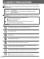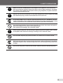
1
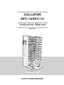
COLLATOR
DFC-12/DFC-10
Instruction Manual
[220-240V]
ILLUSTRATION : DFC-12
DUPLO CORPORATION
DECLARATION OF CONFORMITY
DUPLO CORPORATION, located at 7-6, Izumi-honcho 1-chome, Komae-shi, Tokyo 201-8666, Japan, declares that the following
product,
• Name of product :
Collator
• Models :
DFC-12 and DFC-12B, 100-240V 50/60Hz
DFC-10 and DFC-10B, 100-240V 50/60Hz
complies with the provisions defined by the regulations listed below.
• Regulation :
Machinery Directive 98/37/EC under EN292-1(1991), EN292-2(1991), prEN1010-1(2002), prEN1010-4(2001),
EN60204-1(1997).
Low Voltage Directive 73 / 23 / EEC under IEC950 2nd (1991) + A1 (1992) + A2 (1993) + A3 (1995) + A4 (1996)
including EN60950 2nd (1992) + A1 (1993) + A2 (1993) + A3 (1995) + A4(1997) + A11 (1997) deviations.
Electromagnetic Compatibility Directive 89 / 336 / EEC under EN55011(1998) + A1 (1999) Class B, EN55014-2
(1997), EN61000-3-2 (1995) + A1 / A2 (1998) / A14 (2000), EN61000-3-3 (1995), EN61000-6-2:1999.
En
ÜBEREINSTIMMUNGSERKLÄRUNG
DICHIARAZIONE DI CONFORMITÁ
Die DUPLO CORPORATION mit Sitz in 7-6, Izumi honcho 1chome, Komae-shi, Tokyo 201-8666, Japan, versichert, daß das
folgende produkt,
DUPLO COPRORATION sita a 7-6,Izumi-honcho 1-chome ,
Komae-shi, Tokyo 201-8666 Japan,dichiara che il seguente
prodotto,
• Bezeichnung des Produkts :
Zusammentragmaschine
• Nome del prodotto :
Fascicolatore
• Modell :
DFC-12 und DFC-12B, 100-240V 50/60Hz
DFC-10 und DFC-10B, 100-240V 50/60Hz
• Modello :
DFC-12 e DFC-12B, 100-240V 50/60Hz
DFC-10 e DFC-10B, 100-240V 50/60Hz
Entspricht den Bestimmungen, wie sie durch die unten
aufgeführten Vorschriften definiert sind.
è conforme ai requisiti definiti dalle norme sotto elencate.
• Vorschriften :
Maschinenrichtlinie 98/37/EC nach EN292-1(1991), EN2922(1991), prEN1010-1(2002), prEN1010-4(2001), EN602041(1997).
Niedervolt-Richtlinie 73/23/EEC nach IEC950 2nd (1991) + A1
(1992) + A2 (1993) + A3 (1995) + A4 (1996) und EN60950 2nd
(1992) + A1 (1993) + A2 (1993) + A3 (1995) + A4(1997) +
A11 (1997) Abweichungen.
EMC-Richtlinie 89/336/EEC nach EN55011(1998) + A1
(1999) Class B, EN55014-2 (1997), EN61000-3-2 (1995) + A1
/ A2 (1998) / A14 (2000), EN61000-3-3 (1995), EN61000-62:1999.
Ge
• Direttiva Bassa Tensione :
Direttiva sui macchinari 98/37/CE in base a EN292-1(1991),
EN292-2(1991), prEN1010-1(2002), prEN1010-4(2001),
EN60204-1(1997).
Direttiva relativa alle apparecchiature a bassa tensione 73/23/
CEE in base a IEC950 2nd (1991) + A1 (1992) + A2 (1993) +
A3 (1995) + A4 (1996) incluso EN60950 2nd (1992) + A1
(1993) + A2 (1993) + A3 (1995) + A4(1997) + A11 (1997)
deviazioni.
Direttiva EMC 89/336/CEE in base a EN55011(1998) + A1
(1999) Class B, EN55014-2 (1997), EN61000-3-2 (1995) + A1
/ A2 (1998) / A14 (2000), EN61000-3-3 (1995), EN61000-62:1999.
It
DECLARATION DE CONFORMITE
DECLARACIÓN DE CONFORMIDAD
DUPLO CORPORATION, située à 7-6, Izumi honcho 1-chome,
Komae-shi, Tokyo 201-8666, Japon, déclare que le produit
suivant ;
DUPLO CORPORATION, con domicilio en 7-6, Izumi honcho
1-chome, Komae-shi, Tokio 201-8666 Japan, declara que el
producto siguiente:
• Nom du produit :
Assembleuse
• Nombre del producto :
Clasificador
• Modèle :
DFC-12 et DFC-12B, 100-240V 50/60Hz
DFC-10 et DFC-10B, 100-240V 50/60Hz
• Modelos :
DFC-12 y DFC-12B, 100-240V 50/60Hz
DFC-10 y DFC-10B, 100-240V 50/60Hz
est conforme aux dispositions définies par les réglementations
suivantes ;
Cumple las disposiciones definidas por las siguientes
reglamentaciones:
• Réglementations :
Directive sur les machines 98/37/EC en application de EN2921(1991), EN292-2(1991), prEN1010-1(2002), prEN10104(2001), EN60204-1(1997)
Directive sur la basse tension 73/23/EEC en application de
IEC950 2nd (1991) + A1 (1992) + A2 (1993) + A3 (1995) + A4
(1996) et EN60950 2nd (1992) + A1 (1993) + A2 (1993) + A3
(1995) + A4(1997) + A11 (1997) derogations.
Directive de compatibilité électromagnétique 89/336/EEC
d’après EN55011(1998) + A1 (1999) Class B, EN55014-2
(1997), EN61000-3-2 (1995) + A1 / A2 (1998) / A14 (2000),
EN61000-3-3 (1995), EN61000-6-2:1999.
Fr
• Reglamentaciones :
Directiva 98/37/CE sobre máquinas bajo EN292-1(1991),
EN292-2(1991), prEN1010-1(2002), prEN1010-4(2001),
EN60204-1(1997).
Directiva sobre baja tensión 73/23/CEE bajo IEC950 2nd
(1991) + A1 (1992) + A2 (1993) + A3 (1995) + A4 (1996)
incluyendo las derogaciones EN60950 2nd (1992) + A1 (1993)
+ A2 (1993) + A3 (1995) + A4(1997) + A11 (1997).
Directiva sobre CEM89/336/CEE bajo EN55011(1998) + A1
(1999) Class B, EN55014-2 (1997), EN61000-3-2 (1995) + A1
/ A2 (1998) / A14 (2000), EN61000-3-3 (1995), EN61000-62:1999.
Sp
1. INTRODUCTION
Thank you for your purchase. To ensure correct usage, please read this instruction manual
thoroughly, especially the section Safety Precautions. After reading, please store this
instruction manual in a safe place for future reference.
2. TABLE OF CONTENTS
1.
INTRODUCTION ............................................. 1
13. DOUBLE-FEED DETECTION FUNCTION .... 34
2.
TABLE OF CONTENTS .................................. 1
14. WHEN BIN ERROR LAMPS LIGHT/BLINK . 36
3.
SAFETY PRECAUTIONS ................................ 2
4.
USAGE PRECAUTIONS ................................. 5
14-1. When an error lamp lights in green ............... 36
14-2. When an error lamp lights in red ................... 36
5.
FEATURES OF THIS MACHINE ..................... 6
6.
NAMES OF PARTS ......................................... 7
7.
NAMES AND FUNCTIONS OF
ARE DISPLAYED .......................................... 38
CONTROL PANEL PARTS .............................. 8
15-1.
15-2.
15-3.
15-4.
When "No Paper" is displayed ...................... 38
When "Tray Full" is displayed ........................ 38
When "Feed error" is displayed ..................... 39
When "Preset Error" is displayed .................. 39
15-5.
15-6.
15-7.
15-8.
When "Mis-Feed" is displayed ...................... 40
When "Double Detect" is displayed .............. 40
When "Paper Jam" is displayed .................... 41
When "Stacker Jam " is displayed ................ 41
8.
PRECAUTIONS ON LOADING PAPER .......... 9
9.
OPERATIONS................................................ 10
10. LOADING PAPER ACCORDING
TO COLLATION MODE ................................. 15
10-1.
10-2.
10-3.
10-4.
Loading paper for normal mode .................... 15
Loading paper for interleaving mode ............ 16
Loading paper for alternative mode .............. 16
Loading paper for block mode ....................... 17
14-3. When an error lamp blinks in green .............. 37
14-4. When an error lamp blinks in red .................. 37
15. WHEN ERROR MESSAGES
15-9. When "Feed Cov. Open" is displayed ........... 42
15-10.When "Int. Setup Error" is displayed ............. 42
15-11.When "On-line err" is displayed .................... 43
10-5. How to load paper when downstream unit
is connected .................................................. 17
10-6. Loading paper according to paper size ......... 18
16. TROUBLESHOOTING ................................... 44
11. USING THE CONTROL PANEL .................... 19
18. LCD MENU .................................................... 47
11-1.
11-2.
11-3.
11-4.
LCD window .................................................. 19
Setting the collation mode ............................ 20
Setting the number of interleaves ................. 21
Setting the count display method .................. 22
17. TROUBLESHOOTING GUIDE ...................... 45
19. CLEANING THE UNIT AND REPLACING
EXPENDABLE PARTS .................................. 51
20. SPECIFICATIONS ......................................... 52
11-5. Setting the paper receiving method .............. 23
11-6. Other settings ............................................... 24
12. CONNECTING THE DOWNSTREAM UNIT .. 27
12-1. Connecting the DBM-120 and DBM-120T .... 27
12-2. Connecting DC-S and DC-S4 ....................... 33
Symbols in this Manual
Following symbols are used in this manual to indicate important particulars. They have the following meanings.
Note
Indicates attentions to be paid
Indicates the page to be referred
in use.
to for related information.
1
3. SAFETY PRECAUTIONS
Always observe the cautions and warnings given below to prevent personal injury or property
damage.
The degree of danger and damage that could occur is indicated on two levels by the
following marks.
WARNING: Ignoring this mark could result in the possibility of serious injury
or even death.
CAUTION: Ignoring this mark could result in the possibility of injury or
physical damage.
The following graphic symbols indicate the various types of action to be performed
or avoided.
This graphic symbol indicates a forbidden action.
means “Do not disassemble.”
means “Do not touch.”
This graphic symbol indicates actions that must be performed.
means “Disconnect the power plug.”
WARNING:
Do not place metal objects or vessels containing liquids on top of the unit. The entry of
any metal object or liquid could result in fire or electrical shock.
Do not insert any metal or easily-combustible object inside this unit. This could result in
fire or electrical shock.
Do not touch or insert foreign objects into any rotating part during operation. This could
result in injury.
Do not remove the cover or back panel. This unit contains high-voltage components that
could cause electrical shock.
Do not disassemble, modify or repair this unit. There is a danger of fire, electrical shock
or injury. Contact your dealer when repairs are necessary.
Use only the power supply voltage specified on the main nameplate. Using other
voltages could result in fire or electrical shock.
Keep this unit and the power cord away from heaters and heater vents. Excessive heat
could melt the cover or power cord covering, and result in fire or electrical shock.
Do not use flammable sprays or solvent inside or near the unit (e.g. when cleaning the
unit).
Such flammable gas or solvent may ignite and cause a fire or combustion.
2
3. SAFETY PRECAUTIONS
Make sure that the combined power consumption of the appliances to be connected
does not exceed the capacity rating of the power outlets or plug receptacles. Exceeding
the capacity rating could cause the power outlets, plug receptacles, or power extension
cords to overheat and catch fire.
Remove any dust that accumulates on the power plug prongs and the surface of the plug
from which the prongs extend. Accumulated dust can result in fire.
If any foreign object such as metal or liquid should enter this unit, immediately turn the
unit off at the power switch and disconnect the power plug from the power outlet. Failure
to do so could result in fire or electrical shock. Contact your dealer immediately.
Do not damage the power cord or power plug. (Do not scratch, alter, bend, twist, pull or
place heavy objects on the power cord or power plug.)
This could result in damage, fire or electrical shock.
Always grip the plug when disconnecting the power plug from the power outlet. Pulling
on the power cord could cause damage, resulting in fire or electrical shock.
Do not handle the power plug with wet hands. This could result in electrical shock.
Before cleaning this unit, turn the unit off at the power switch and disconnect the power
plug from the power outlet. Accidental operation of the unit during cleaning could result
in injury.
Do not touch the power switch with wet hands. Otherwise electric hazards may occur.
3
3. SAFETY PRECAUTIONS
CAUTION:
Always disconnect the power plug from the power outlet when the unit is not to be used
for an extended period. Failure to do so could result in fire due to leakage current if the
insulation should deteriorate.
Install this unit on a level, stable stand or floor, with sufficient space around it. Failure to
do so could result in the unit overturning and causing injury.
Do not install this unit in a location where there is excessive humidity or where contact
with water is possible. Poor choice of location could result in deterioration of the
insulation, fire or electrical shock.
Disconnect the power plug from the power outlet before attempting to move this unit.
Failure to do so could result in power cord damage, fire or electrical shock.
4
4. USAGE PRECAUTIONS
Power supply
• This equipment shall be installed near the socket-outlet where the plug on the power supply
cord is easily accessible.
• Make sure the power supply used is always within the following range.
100-240V AC, 50/60Hz
• When you power other appliances from the same AC outlet, make sure that the combined
power consumption does not exceed the power supply capacity.
Rated power of this equipment : 2.8-1.2A(DFC-12) / 2.0-0.8A(DFC-10)
Operating environment
Operate this unit in the following environment:
• where the temperature range is between
5 and 35°C,
• where the humidity range is between 20
and 85%RH (no dew condensation),
• which is not subject to direct sunlight,
• which is subject to little or no vibration,
•
•
•
•
where there are no harmful chemicals,
which is reasonably free from dust,
which is free from air-borne salt, and
where the equipment is not exposed to
water.
Storage conditions
Store this unit in the following environment:
• where the temperature range is between
-10 and +50°C,
• where the humidity range is between 10
and 90%RH (no dew condensation),
• which is not subject to direct sunlight,
• which is subject to little or no vibration,
•
•
•
•
where there are no harmful chemicals,
which is reasonably free from dust,
which is free from air-borne salt, and
where the equipment is not exposed to
water.
Maintenance
To protect the special features of this unit, the customer should never apply oil or grease to
the parts.
Please contact your dealer in case of any problem.
5
5. FEATURES OF THIS MACHINE
The DFC-12 and DFC-10 can collate paper sizes from A5 to A3SR.
○
○
○
○
○
○
○
○
○
○
○
○
○
○
○
○
○
○
○
○
○
○
○
○
○
○
○
○
○
○
○
○
○
○
○
○
○
○
○
○
○
○
○
○
○
○
The DFC-12 can collate 12 sheets and the DFC-10 can collate 10 sheets.
○
○
○
○
○
○
○
○
○
○
○
○
○
○
○
○
○
○
○
○
○
○
○
○
○
○
○
○
○
○
○
○
○
○
○
○
○
○
○
○
○
○
○
○
○
○
○
○
○
○
○
○
○
○
○
○
○
○
○
○
○
○
○
○
○
○
○
○
○
By connecting two DFC-12 (DFC-10) machines, up to 24 (20) sheets can be collated.
The following four collation methods are available.
○
○
○
○
○
○
○
○
○
○
○
○
○
○
○
○
○
○
○
○
○
○
○
○
○
○
○
○
○
○
○
○
○
○
○
○
○
○
○
○
○
○
○
○
○
○
○
○
○
○
Normal mode: Collates paper on the bins from the top tray in order and ejects as one set.
Interleaving mode: Inserts interleaves after every specified number of sets processed
to separate the collated sets.
Block mode: Divides the paper on the bins into the upper half block and lower half block and
collates paper.
Alternative mode: The same pages can be divided into two piles and stacked on continuing
odd and even bins, and collated taking the two bins as one bin. For details, refer to "10. LOADpage 15).
ING PAPER ACCORDING TO COLLATION MODE" (
Collated sets can be received in "offset mode" or "straight mode".
○
○
○
○
○
○
○
○
○
○
○
○
○
○
○
○
○
○
○
○
○
○
○
○
○
○
○
○
○
○
○
○
○
○
○
○
○
○
○
○
○
○
○
○
○
○
○
○
○
○
○
○
○
○
○
For details, refer to "11-5. Setting the paper receiving method" of "11. USING THE CONTROL
PANEL" (
page 23).
The optional downstream units (DBM-120, DBM-120T, DC-S, DC-S4) can be connected.
○
○
○
○
○
○
○
○
○
○
○
○
○
○
○
○
○
○
○
○
○
○
○
○
○
○
○
○
○
○
○
○
○
○
○
○
○
○
○
○
○
○
○
○
Downstream units to bind, punch, or trim collated paper can be connected.
6
○
○
○
○
○
○
○
○
○
○
○
6. NAMES OF PARTS
(The illustration shows the DFC-12)
Paper feed ring
Control panel
Movable guide
Bin
Fixed guide
Auxiliary paper
feed bin
Sliding plate
Paper feed pressure adjusting knob (on every bin)
Vertical conveyance cover
Back jogger
Paper receiving stopper 2
Power switch
Side guide B
Port for power cord
Side guide F
Handle
Paper receiving stopper 1
Paper receiving table
Connector for other units
Connector for downstream unit
Connector port for delivery unit
Used also for connecting conveyance bridge
Paper separation pressure adjusting lever (on every bin)
7
7. NAMES AND FUNCTIONS OF CONTROL PANEL PARTS
bl
(The panel is the DFC-12)
bm
bk
9
bn
8
7
bo
1
2
3
4
5
6
7
8
9
0
C
6
5
No.
1
2
3
Name
Start key
Stop key
Preset key
4
Eject key
5
6
7
8
Clear key (C )
Numerical keys (0 to 9)
Scroll key
Escape key
9
Enter key
bk
NO. OF SETS window
bl
LCD window
bm
Bin error lamp
When lit in green:
When blinking in green:
When lit in red:
When blinking in red:
bn
Mode display lamp
bo
Select key
2
1
Function
Press this key to start operating the unit. (
Page 14)
Press this key to stop the unit. (
Page 14)
Press this key before starting the first collation job. (
Page 14)
Paper for one set is sent from the paper feed bins to memorize the length
and thickness of the paper, and the number of bins used.
Press this key when paper jams. (
Page 41)
The motor will rotate while pressed to eject the jammed paper out.
Use for clearing the number entered to "0". (
Page 22)
For entering the number of sets to be collated.(
Page 22)
Use this key to scroll the LCD menu.(
Page 20)
Press this key to return to the standby screen after completing settings at
the menu screen.(
Page 20)
Press this key to change the menu screen and to confirm settings. (
Page
20)
Displays the number of collated sets or the number of sets remaining for
collation.(
Page 22)
For checking the current operating status of the unit or the current collation
mode.(
Page 19)
Lights or blinks at the bin with the paper feed error. (
Page 36,37)
Indicates no paper. (
Page 36)
Indicates Empty-feed.(
Page 37)
Indicates paper has jammed.(
Page 36)
Indicates double-feed.(
Page 37)
During presetting, bins with no paper will light up in green.(
Page 14)
Indicates the lamp to switch between the offset mode, straight mode, or
optional mode*. (Both lamps will be off when the straight mode is
selected.)(
Page 23)
Press this key to change the paper ejection direction and paper receiving
method.(
Page 23)
*Lights up only when a downstream unit is connected.
8
4 3
8. PRECAUTIONS ON LOADING PAPER
Fan paper sufficiently before loading on the
bin.
• If the paper is not separated well, mis-feed,
double-feed or paper jam may occur.
• Flatten folded or curled paper before stacking.
Align the lead edge of the paper stock, and
place it on the bin.
• If the paper is not loaded neatly mis-feed, or
double-feed may occur.
Make sure that ink on the paper has dried
completely.
• If not, not only will the unit become dirty, but
other problems (double-feed, mis-feed, paper
jam) may occur.
9
9. OPERATIONS
Flowchart of operations
The following shows the flowchart of the basic operations.
For details, refer to the text and corresponding pages.
Start
1. Turn ON the power switch
(
2. Adjust the paper feed pressure
• Set the paper feed pressure adjusting knob to the
paper size. (
Page11)
3. Adjust the paper separation pressure
• Set the paper separation pressure adjusting lever
to the paper thickness. (
Page11)
4. Load paper on the bin
Page11)
• The method of stacking paper differs according to
the collation mode used. (
Page15~18)
When using the downstream unit.
5. Adjust the position of paper receiving stopper 1
• Adjust the position to the paper size.
(
Page12)
6. Adjust the position of paper receiving stopper 2
• Adjust the position to the paper size.
(
Page12)
7. Adjust the position of side guide F
• Adjust the position to the paper size.
(
Page13)
8. Move the side guide B
• Move the side guide B according to the collation
mode offset mode or straight mode.
(
Page13)
9. Set the control panel.
9-1. Set the collation mode
(
Page20)
9-2. Set the count display method
(
Page22)
(
Page23)
9-3. Set the paper receiving method
Downstream unit setting
(DC-S,DC-S4)
(
Downstream unit setting
(DBM-120+DBM-120T)
(
10. Check paper ejection
Page33)
• Press the Preset key.
(
Page14)
Page27)
Set the binding method
(
Page27)
Set the paper size
11. Start/stop operations
12. Turn OFF the power switch
• Press the Start key.
To stop operations, press
the Stop key.(
Page14)
(
Page14)
(
Set the trimmer
(
10
Page31)
Settings after clearing
paper feed error
(
End
Page28)
Page32)
9. OPERATIONS
1
Turn ON the power switch.
Interruptor de alimentación
• Pressing "I" turns ON the power supply.
Pressing "O" turns OFF the power supply.
When the downstream unit is connected, turning
ON the power switch of the DFC-12/10 will automatically turn ON the power of the downstream unit
ON
OFF
as well by the remote function. Be sure to wait for
more than 10 seconds when switching ON again
after having switched OFF.
WARNING
Do not touch the power
switch with wet hands.
Otherwise electric hazards may
occur.
2
Set the paper feed pressure adjusting
knob to the paper size.
Note
As a paper feed pressure adjusting
knob is provided for each bin, adjust
Strong
Normal
each knob to the paper size.
• If the paper size is less than A3, set the knob to
the right position (normal).
• If the paper size is more than A3, set the knob to
the left position (strong).
3
Adjust the paper separation pressure
adjusting lever to the paper thickness.
Note
As a separator pressure adjusting le-
Paper feed pressure adjusting knob
Low
High
Paper separation pressure
adjusting lever
ver is provided for each bin, adjust each
lever to the paper thickness.
• When using thick paper, move the lever to the
left (where the pressure is low).
• When using normal paper, move the lever to the
center.
• When using thin paper, move the lever to the
right (where the pressure is high).
11
9. OPERATIONS
4
Fixed guide
Load the paper on the bins.
Paper feed gate
Paper
Insert the paper along the fixed guide until it
touches the guide of the paper feed gate lightly.
• The maximum height of paper which can be
stacked is 28 mm. Be careful not to overstack.
Contact the movable guide lightly to the edge
of the paper.
Note
The method of loading paper differs
Movable guide
Paper
according to the normal mode, interleaving mode, block mode, and alternative mode.
For details, refer to "10. LOADING
PAPER ACCORDING TO COLLATION
MODE" (
page 15).
Proceed to step 9 when using the
downstream unit.
5
Move and adjust the paper receiving
stopper 1 to the paper size.
Paper size
scale
The paper size scale on the paper receiving
table is at the standard position for each paper
size.
If paper is not stacked properly, or if paper is
crushed by the back jogger, adjust the knob to
move the paper receiving stopper 1 back and
forth.
6
Paper size scale
Paper receiving
stopper 1
Knob
Paper receiving stopper 1
Move and adjust the paper receiving
stopper 2 to the paper size.
Paper receiving
stopper 2
Paper size scale
Paper receiving stopper 2
12
9. OPERATIONS
7
Adjust the side guide F to the paper size.
Side guide F
B5
11x17
LGL. LTR IV
A4. A5
B4. B5
Paper size scale
Side guide F
8
When set to the STRAIGHT mode, move
the side guide B until it touches the paper receiving table. When set to the OFFSET mode, move it until it touches the
side frame.
Side frame
Side guide B
OFFSET mode
STRAIGHT mode
Paper receiving table
9
Set the collation mode, paper receiving
method, and count display method on
the control panel.
• For details, refer to "11. USING THE CONTROL
PANEL" (
page 19).
• When using the downstream unit, refer to "12.
CONNECTING THE DOWNSTREAM UNIT"
(
page 27).
1
2
3
4
5
6
7
8
9
0
C
13
9. OPERATIONS
10
Press the Preset key.
One set of paper is sent from the bin.
Note
If the set is not aligned properly, finely
adjust the paper receiving stoppers 1
and 2, and side guide F. (
Refer to
pages 12, 13.)
• The paper feed error lamp of bins with no paper
will light up in green.(
Page 36)
• This preset function differentiates between bins
with paper and those without, and memorizes the
length and thickness of the paper on each bin.
Based on this data memorized, double-feed is
detected.
• For details, refer to "13. DOUBLE-FEED DETECTION FUNCTION" (
page 34).
Take the ejected set and check that the paper
has been collated properly. If not collated properly, check the location of the error on the control panel.
11
Press the Start key and start operations.
Stop key
Start key
To stop operations, press the Stop key.
12
Turn OFF the power after completing operations.
Interruptor de alimentación
The collation mode, the paper size and the processing mode when the downstream unit is
connected are preserved even after the power
has been turned OFF.
WARNING
Do not touch the power
switch with wet hands.
Otherwise electric hazards
may occur.
14
ENCENDIDO
APAGADO
10. LOADING PAPER ACCORDING TO COLLATION MODE
Determine how to load paper according to the operation to be carried out after collation.
See the figures below for the order of loading paper on the bins and collation pages.
Note
If using the downstream unit, whether to face the printed side up or down differs according to the processing method. Refer to the instruction manual of the downstream unit.
10-1. Loading paper for normal mode
Paper is fed from the top bin in order and ejected to the paper receiving table as one
set.
Paper
(Printed side)
When paper is loaded with its printed side facing up
When paper is loaded with its printed side facing up, the printed side of the collated paper will face down.
Paper
(When loaded)
Paper
(When ejected)
Page 1
Page 2
Page 3
Page 11
Page 12
Paper
(When loaded)
Paper
(When ejected)
Page 1
Page 2
Page 3
Page 11
Page 12
Page 12
Page 12
Page 1
Page 1
Paper
(Non-printed side)
When paper is loaded with its printed side facing down
When paper is loaded with its printed side facing down, the printed side of the collated paper will face up.
Paper
(When loaded)
Paper
(When ejected)
Page 12
Page 11
Page 10
Page 2
Page 1
Paper
(When loaded)
Paper
(When ejected)
Page 12
Page 11
Page 10
Page 2
Page 1
Page 1
Page 1
Page 12
Page 12
15
10. LOADING PAPER ACCORDING TO COLLATION MODE
10-2. Loading paper for interleaving mode
• Interleaves are inserted after every
specified number of sets have been collated.
• Interleaves are inserted after every 200
sets maximum.
Load the interleaves at the bottommost
bin.
Page 1
Page 2
Page 3
Page 4
Page 5
Page 6
Page 7
Page 8
Page 9
Páginas clasificadas
Load in bin 12 for the DFC-12 and in bin
10 for the DFC-10. See the right figure for
details.
Intercalado
Páginas para
intercalado
Intercalado
Intercalado
• For details on the loading direction of paper
and paper ejection direction, refer to "10-1.
Loading paper for normal mode" (
Intercalado
page
15).
• Interleaving mode is shown as "Int. Lv." in the
LDC window.
10-3. Loading paper for alternative mode
Load the same paper on continuing even
and odd (top and bottom) bins from the
top in order (1st and 2nd bins, 3rd and
4th bins....11th and 12th bins) for colla-
Páge 1
tion.
Page 2
Paper feed starts from either bin (odd or
Page 3
even) of each pair.
Page 4
If paper runs out in a bin, paper feed will
Page 5
start from the other bin in the pair. By replenishing paper in the empty bin, continu-
Page 6
ous operations can be ensured.
• For details on the loading direction of paper
and paper ejection direction, refer to "10-1.
Loading paper for normal mode" (
15).
16
page
10. LOADING PAPER ACCORDING TO COLLATION MODE
10-4. Loading paper for block mode
The bins can be divided into two blocks
(6 bins each) to collate paper in blocks.
Page 1-a
Page 2-a
Page 3-a
Page 4-a
Page 5-a
Page 6-a
Page 1-b
Page 2-b
Page 3-b
Page 4-b
Page 5-b
Page 6-b
For the DFC-10, bins are divided likewise
5 bins each.
Paper feed starts from bins 1 to 6 (block 1/
2). When paper on any bin of the block runs
outs, operation is stopped. Press the Start
key to switch paper feed to bins 7 to 12 (block
2/2).
Group of block 1/2
Group of block 2/2
Group of block 2/2
• For details on the loading direction of paper
Group of block 1/2
and paper ejection direction, refer to "10-1.
Loading paper for normal mode" (
page
15).
10-5. How to load paper when downstream unit is connected
• Paper ejected from the DFC-12/10 is punched, stapled, folded, and trimmed as shown
below by a downstream units.
• The interleaving mode cannot be set if a downstream unit is connected.
Página 1
Page 2
Page 3
Page 4
Page 5
Page 6
Page 7
Page 8
Page 9
Page 10
Page 11
Page 12
Page 1
Page 2
Page 3
Page 4
Page 5
Page 6
Page 7
Page 8
Page 9
Page 10
Page 11
Page 12
Side stapling
Page 1
Page 2
Page 3
Page 4
Page 5
Page 6
Page 7
Page 8
Page 9
Page 10
Page 11
Page 12
Side stapling
Page 1
Page 12
Page 1
Saddle stapling
DC-S4 (When attaching the option)
Page 12
Corner stapling
Saddle stapling
DC-S4
DC-S
DBM-120 + DBM-120T
Punched holes
Corner stapling
Page 1
Side stapling
DC-S4 (When attaching the option)
DC-SP
DC-S
Page 12
Side stapling
DBM-120
17
10. LOADING PAPER ACCORDING TO COLLATION MODE
10-6. Loading paper according to paper size
The direction differs according to paper size.
● Paper loading direction available
Paper size
Direction
A5
A4
A3
A3SR
B5
B4
LGL
LTR
LGR
INV
⇑
%
?
?
?
?
?
?
?
?
%
⇑
?
?
X
X
?
X
X
?
X
?
? : Available
X : Not available
% : Available when DBM-120 and DBM-120T are connected
• LGL = Legal (8.5” x 14”) LTR = Letter (8.5” x 11”) INV = Invoice (8.5” x7”) LGR = Double letter (11” x
17”)
• The compatible paper sizes for the DC-S are A4, B5, B4, and LGL in the above table. (Stack vertically
for all)
• The compatible paper sizes for the DC-S4 are A5, A4, B5, and LTR in the above table. (However A5
paper cannot be loaded vertically)
When paper size is A5, and INV
• Be sure to load horizontally when not connecting a downstream unit.
• When loading paper vertically, the optional
"small paper size kit" will be required. However
this applies only when the DBM-120 is connected.
When paper size is B4 and LGL
• Load vertically.
When paper size is A3, A3SR, and LGR
• Pull out the sliding plate and load vertically.
18
Sliding plate
11. USING THE CONTROL PANEL
This section describes the contents of the LCD and how to set the collation mode, paper
receiving mode, and count display method.
11-1. LCD window
Collation mode menu
Paper size
Operating state
No. of interleaves
No. of processing sets
● Paper size
• Set when using the downstream unit.
If no downstream unit is connected, the paper size will not be displayed.
• Displays the paper size saved.
Select from A3, A4, A5, B4, B5, LGR, LGL, LTR, INV, A3SR, custom 1, custom 2, custom
3. (For details on setting the paper size, refer to "12. CONNECTING THE DOWNSTREAM
UNIT" (page 27).)
• The settings will be preserved even after the power is turned OFF.
● Collation mode menu
• Displays the collation mode saved.
Select the collation mode from NORMAL, INTERLEAVING, BLOCK, and ALTERNATIVE.
• The settings will be preserved even after the power is turned OFF.
Note
If connecting the downstream unit, only the INTERLEAVING mode settings will
not be preserved.
● No. of interleaves
Displays the number of interleaves entered.(
Refer to page 21.)
Displays only when the interleaving mode is set.
● Operating state
For checking the current operating state of the unit.
Running .................... Currently feeding paper
Standby .................... Currently standing by
When set to the block mode, displays from which block paper is being fed.
1/2,2/2
Block mode
● No. of processing sets
Displays the number of sets entered by the count down display method.
19
11. USING THE CONTROL PANEL
11-2. Setting the collation mode
Select the collation mode from NORMAL, INTERLEAVING, BLOCK, and ALTERNATIVE.
• The "Block 4"cannot be selected when using the DFC-12/10 separately.
• The interleaving mode cannot be selected when paper is ejected to a downstream unit.
• When using the interleaving mode, set the number of interleaves.
1
Press the
key and display
the "Mode menu".
2
Pressing the
key switches the
screen between NORMAL, Int.LV.,
BLOCK, and ALTERNATIVE.
4
To redo the setting, press the
other time to return to step 3.
5
3
Press the
key and display
the screen where the desired collation mode is blinking.
Press the
key and save the collation mode selected at step 3.
Press the
key to return to the
standby screen.
Press the
key until the standby screen
is displayed.
* Int. Lv. ······ Interleaving mode
* ALT ··········· Alternative mode
20
key an-
11. USING THE CONTROL PANEL
11-3. Setting the number of interleaves
When the interleaving mode is selected, interleaves will be inserted after every specified number of sets have been collated. Enter the number of interleaves at the "Sheet
Quantity" screen.
Up to 200 sets can be specified to insert interleaves.
1
Press the
key to display the
"Sheet Quantity" screen.
4
Press the
key and save the number of interleaves entered at step 3.
To redo the setting, press the
key an-
other time to return to step 3.
2
Press the
key and switch to the
"Input Sheet Qty" screen.
5
Press the
key to return to the
standby screen.
number of interleaves
3
Enter the number of interleaves using the numerical keys. If the previous setting of the number of interleaves is remaining, press the
key to clear to 0 first before entering the new number.
Press the
key until the standby screen
is displayed.
Check that the number of interleaves is
displayed at the top right of the screen.
* Qty ··········· Quantity
1
2
3
4
5
6
7
8
9
0
21
11. USING THE CONTROL PANEL
11-4. Setting the count display method
Select the count display method from the count up display and count down display.
Count up display method
1
2
3
LCD window
The NO. OF SETS window counts up the
number of collated sets during operations.
When the required number of sets is
reached, press the Stop key to stop the
unit.
4
5
6
7
8
9
0
C
NO.OF SETS window
Operations stop when the display
reaches “9999”.
• Check that the NO. OF SETS window shows 0. To clear to 0, press the
key.
Count down display method
The NO. OF SETS window counts down
the number of unprocessed sets (remaining sets to be processed) during opera-
1
2
3
LCD window
4
5
6
7
8
9
tions. When the display reaches 0, the
unit stops.
NO. OF SETS window
0
1 Check that the NO. OF SETS window
C
shows 0. To clear to 0, press the
key.
2 Enter the number of sets to be collated
Dot mark
using the numerical keys. Up to 9999 can
be entered.
3 Check that the number of processing sets entered is displayed at the LCD and NO. OF SETS win-
dow.
When collating repeatedly in the same number of sets, turning ON the "Processed sets
repeat setting" enables repeated collation by restarting the unit.
When the number of processing sets repeat setting is ON, a dot mark will be displayed on
the NO. OF SETS window. This dot mark will not be displayed if the setting is OFF.
For details, refer to "Setting processed set repeat" (
page 26) of "11-6. Other settings".
Total count display
The total number of sets which have been collated can be checked using the Stop key.
• Pressing the Stop key for more than one second while the unit is stopping displays the total number
of sets.
• Releasing the Stop key clears the display.
Note
•The number of sets displayed is the total number of sets from when the power
was turned ON to the end of collation. When the power is turned OFF, the
number of sets displayed will be cleared to 0.
•If more than 9999 sets have been processed, the number of sets display will clear to 0
and start counting again.
•To reset the total count to 0, press the
key while pressing STOP key for more
than one second.
•Opening the vertical conveyance cover during operations stops the operation immediately and the NO. OF SETS window may show a different count from the number of sets
actually collated.
22
11. USING THE CONTROL PANEL
11-5. Setting the paper receiving method
• Paper can be ejected to the paper
receiving table in two ways; the
OFFSET mode which sorts paper
ejected onto the table into sets and
Straight mode
Offset mode
the STRAIGHT mode which stacks
sets into one pile.
• Select "OPTION" when using the
downstream unit.
• Press the Select key and set the paper receiving mode.
• When OPTION is selected, paper will
not be ejected to the paper receiving
table.
• To switch between the two modes
during operations, be sure to adjust
side guide B. (
page 13)
OFFSET mode
OPTION mode
STRAIGHT mode
Press the Select key to light up
Press the Select key to light up
Press the Select key to turn off
the OFFSET lamp.
the OPTION lamp.
the OFFSET and OPTION
lamps.
OPTION can not be selected when
the downstream unit is not connected.
23
11. USING THE CONTROL PANEL
11-6. Other settings
If the paper ejected to the downstream unit or paper receiving table is not aligned properly, or the same collation operation is repeated, perform the "Overlap", "Speed", and
"Processed set repeat" settings at the "Other Settings" screen on the control panel.
5mm (0.2")
Setting overlap
Overlap : Small
If paper ejected to the downstream unit is not
aligned properly, this can be improved by shifting
overlap of collated paper during ejection.
10mm (0.39")
At shipment, “Overlap ” is set to “None”.
Note Set to “None” when ejecting to the pa
Overlap : Large
per receiving table.
1
2
key to display
3
Press the
key to display the
screen where the overlap to be set
is blinking.
Press the
key and display the
screen for selecting “Overlap",
"Speed", and Initial Qty Rpt".
4
Press the
key and save the Overlap selected at step 3.
Press the
"Other settings".
Press the
key to display the "
Overlap" screen, and next press
the
To redo the setting, press the
key to display the screen for se-
key an-
other time to return to step 3.
lecting the overlap .
Adjust the overlap while checking the paper
alignment state.
5
Press the
key to return to the
standby screen.
Press the
is displayed.
24
key until the standby screen
11. USING THE CONTROL PANEL
Setting speed
For auto, the speed is adjusted automatically according to the paper size, number of sheets, overlap,
paper receiving mode, and whether the downstream unit is connected or not. Delay the processing
speed if the paper ejected to the downstream unit is not aligned properly or if errors occur frequently
when the downstream unit is connected.
Select speeds from auto, 5, 4, 3, 2, 1 (the speed drops from 5 towards 1).
At shipment, “Speed” is set to “Auto”.
Note
When the downstream unit is connected, set the speed to less than 3.
5 and 4 cannot be selected.
The processing speed will change when the "Overlap" setting is changed.
1
Press the
"Other settings".
key to display
3
Press the
key to display the
screen where the speed to be set is
blinking.
2
Press the
key to set the screen
for selecting "Overlap ", "Speed",
and “Initial Qty Rpt".
4
Press the
key and save the
speed selected at step 3.
Press the
key to display the
"Speed" screen, and next press
the
To redo the setting, press the
key to display the screen for se-
key an-
other time to return to step 3.
lecting speed.
5
Press the
key to return to the
standby screen.
Press the
key until the standby screen
is displayed.
25
11. USING THE CONTROL PANEL
Setting processed set repeat
Set the "Initial Qty Rpt" screen to ON to repeat the same collation operation with the count down
display method.
The number of sets entered will be memorized and the same collation will be carried out continuously.
At shipment, “Initial Qty Rpt” is set to “ON”.
1
Press the
"Other settings".
key to display
4
Press the
key and save the repeat operations selected at step 3.
*1
To redo the setting, press the
other time to return to step 3.
2
Press the
key to set the screen
for selecting "Overlap", "Speed",
and “Initial Qty Rpt".
Press the
5
key an-
Press the
key to return to the
standby screen.
key to display the
"Initilal Qty Rpt" screen, and next press
the
key to display the screen for select-
ing repetition of number of processed sets.
Press the
key until the standby screen
is displayed.
*1: When the processed sets repeat setting is
"ON", a dot mark will be displayed on the
NO. OF SETS window. This dot mark will
not be displayed if the setting is "OFF".
LCD window
3
Press the
key to display the
screen where the operation to be set
is blinking.
NO. OF SETS window
Dot mark
* Initial Qty Rpt ·········· Initial Quantity Repeat
26
12. CONNECTING THE DOWNSTREAM UNIT
12-1. Connecting the DBM-120 and DBM-120T
Downstream units (DBM-120, DBM-120T) can be connected to the DFC-12/10 to staple, fold, and
trim collated paper.
Set the "Binding", "Paper size", "Custom size","Trimmer", and "After clearing paper feed errors"
at the control panel.
Perform the following settings after pressing the Select key on the control panel, and select
"Option" (
Note
page 23).
When finely adjusting paper alignment, stapling and folding positions on the DBM-120, settings cannot be
performed on the control panel. If using the downstream unit without selecting "Options", change the
settings of "Binding", "Paper size", "Custom size", and "Trimmer" at the control panel of the downstream
unit. When using only the downstream unit, turn ON DFC-12/10.
Setting binding method
3
Set the binding method of DBM-120 using the following procedure.
Press the
key to display the
screen for selecting the binding
method.
(For details of binding methods, refer to the instruction manual of DBM-120.)
Press the
At shipment, the binding method is set to
“Through”.
1
screen where the binding method to be
set is blinking.
Press the
key and display
"On-line setting".
4
2
key to display the
Press the
key and display the
screen for selecting "Booklet
maker", "Trimmer", and "Error paper
ejection".
Press the
key and save the binding method selected at step 3.
To redo the setting, press the
key an-
other time to return to step 3.
Press the
key to display the
"Booklet maker" screen, and next press
the
screen.
key to display the binding method
5
Press the
key to return to the
standby screen.
Press the
key until the standby screen
is displayed.
27
12. CONNECTING THE DOWNSTREAM UNIT
Setting paper size
3
Press the
key and save the paper size selected at step 2.
Paper size can be selected from A3, A4, A5, B4,
B5, LGR, LGL, LTR, INV, A3SR, custom 1, custom 2, and custom 3.
To set custom 1 to 3, the paper length and width
must be registered. For details, refer to "Setting
To redo the setting, press the
other time to return to step 2.
the custom size"
At shipment, “Paper size” is set to “A3”.
1
Press the
"Paper size".
key an-
key and display
4
Press the
key to return to the
standby screen.
Paper size saved
Press the
key until the standby screen
is displayed.
2
Press the
key and display the
screen for selecting the paper size.
Note
Some paper sizes cannot be selected
depending on the bound state.
If the paper size of your choice cannot be
Press the
key to display the
screen where the paper size to be set is
blinking.
28
selected, select the binding state first according to "Setting binding method" on
page 27 and then set the paper size.
After completing settings, check the paper size displayed at the standby screen.
12. CONNECTING THE DOWNSTREAM UNIT
Setting custom size
3
When using paper other than those specified, register the length and width of the paper. Three paper sizes can be registered (custom 1, custom 2,
custom 3).
Pressing the
key switches between the screens for selecting length and
width.
At shipment, A4 size paper length and width are
registered at every custom size.
1
Press the
"Custom size".
2
Press the
key and display the
screen for selecting custom 1 to 3.
Select the screen of the custom
number to be registered, and press
the
key. The screen for setting
the length (L) and width (W) is displayed.
key and display
Pressing the
key switches between the screens for selecting custom 1
size, custom 2 size, or custom 3 size.
4
Select the screen for registering the
size, and press the
key to switch
between the "Set Length" or "Set
Width" screen.
Screen for registering length
Screen for registering width
29
12. CONNECTING THE DOWNSTREAM UNIT
5
Enter the length or width using the
numerical keys.
7
Press the
key to return to the
standby screen.
If any previously registered size of
paper length or width is remaining,
key to clear to " 0 "
press the
first before entering the new number.
The length and width ranges which can
be registered differ according to the binding method.
• Saddle stapling / folding
Length: 200 to 450 mm
Width: 200 to 320 mm
• Side stapling
Length: 139 to 231 mm
Width: 200 to 320 mm
• Corner stapling
A4 size ( Length: 210 mm Width: 297 mm )
6
Press the
key and register the
value entered at step 5.
Note Values out of the specified range
will not be registered even if entered. If such values are entered,
the display will return to the previous value. Enter values within the
specified range.
To redo the setting, press the
key and
register the value entered at step 5.
30
Press the
key until the standby screen
is displayed.
12. CONNECTING THE DOWNSTREAM UNIT
Setting trimmer
Set whether or not to use the trimmer (DBM-120T) connected to DBM-120 using the following
procedure.(For details on the trimmer, refer to the instruction manual for DBM-120T.)
At shipment, “Trimmer” is set to “ON”.
1
Press the
key and display
"On-line setting".
4
Press the
key and save the trimming method selected at step 3.
To redo the setting, press the
key an-
other time to return to step 3.
2
Press the
key and display the
screen for selecting "Booklet
maker", "Trimmer", and "Error paper
ejection".
Press the
5
Press the
key to return to the
standby screen.
key to display the
"Trimmer" screen, and next press the
key to display the trimmer screen.
Press the
key until the standby screen
is displayed.
3
Press the
key to display the
screen for selecting trimmer.
Press the
key to display the
screen where the operation to be set is
blinking.
31
12. CONNECTING THE DOWNSTREAM UNIT
Setting "After clearing paper feed error"
Paper conveyed to the downstream unit when paper feed error occurs (no paper, mis feed, double-feed,
etc.) will be ejected without binding. In this case, operations of the DFC-12/10 can be stopped or continued according to preference. At shipment, “Error paper ejection” is set to “Stoppage”.
1
Press the
key and display
"On-line setting".
4
Press the
key and save the operation selected at step 3.
To redo the setting, press the
2
key an-
other time to return to step 3.
Press the
key and display the
screen for selecting "Booklet
maker", "Trimmer", and "Error paper
ejection".
Press the
5
Press the
key to return to the
standby screen.
key to display the "Er-
ror paper ejection" screen, and next press
key to display the after clearing
the
screen.
Press the
key until the standby screen
is displayed.
Note
• Even though “Continuation” is selected,
operations stop when feeding errors occur twice successively. In case of high
speed, another set may be fed after those
erroneous sets. This set will be, however,
ejected without binding.
3
Press the
key to display the
screen for selecting whether to continue or stop operations after ejection.
• When On-line setting is set to “Through”,
any error stops operations even though
“Continuation” is selected.
• If errors (empty-feed, double-feed, ) occur for the last set in collation when the
count display method is set to "count-
Press the
key to display the
screen where the operation to be set is
blinking.
32
down method", the machine will stop
when count is 1 even though "Continuation" is selected.
12. CONNECTING THE DOWNSTREAM UNIT
12-2. Connecting DC-S and DC-S4
• Downstream units (DC-S, DC-S4) can be connected to the DFC-12/10 to staple and punch
collated paper.
• The paper sizes which can be used differ between DC-S and DC-S4. For details, refer to their
instruction manuals. The special connecting kit (PS-Base) is required to connect DC-S and
DC-S4.
It can be purchased from the nearest Duplo dealer.
• When connecting DC-S or DC-S4, press the Select key on the control panel of the DFC-12/10
and select "Option". For details, refer to "11-5. Setting the paper receiving method" (
page
23)
DC-S
DC-S4
33
13.DOUBLE-FEED DETECTION FUNCTION
Using the sensor for measuring paper thickness, the thickness of paper fed by preset
settings is read as the reference data, and compared with the data of the paper collated.
When the difference between those data is large, it determines that a double-feed has
occurred.
This function is called double-feed detection.
The sensor is inside the paper feed gate of
each bin.
Light-receiving sensor
The light-emitting sensor located below paper emits
some amount of light at the light receiving sensor lo-
Paper feed ring
Paper
cated above paper. The sensor above measures the
light amount penetrating the paper from below.
Light-emitting sensor
• Sensor reading range:
Light-receiving sensor
The sensors read along the line 160 mm from the side
edge ranging from the point 10 mm off the top edge up
to 110 mm.
160mm
When a black print is at this position, the light amount
on the paper drops, disabling the sensor from operat-
Light-emitting sensor
Paper direction
10mm
ing normally. In such cases, turn off the double-feed
detection sensor.
Paper
For details on setting, refer to "Switching the doublepage
100mm
feed detection sensor between ON/OFF" (
35).
Note
When using the double-feed detection sen-
Paper
160mm
sor at OFF, the machine will not stop even if
double-feed error occurs.
Sensor reading range
34
13.DOUBLE-FEED DETECTION FUNCTION
Switching the double-feed detection sensor between ON/OFF
1
Press the
key and display
"Double detect Set".
5
Press the
sor state.
key to save the sen-
To redo the setting, press the
key an-
other time to return to step 4.
2
Press the
key and display the
ON/OFF state of the sensor.
6
Press the
key to return to the
standby screen.
The sensor number corresponds to the or-
3
der of the bins from the top in the order of
Press the
sensor 1, 2, 3….12. (DFC-10 has up to
sensor 10.)
is displayed.
key until the standby screen
Press the
key and select the
sensor whose setting is to be
key.
switched, and press the
The screen for selecting sensor ON/OFF
will be displayed.
4
Press the
key, and select
the screen where the sensor state
to be selected is blinking.
35
14. WHEN BIN ERROR LAMPS LIGHT/BLINK
When paper feed errors occur during operations, the warning alarm sounds, and
the bin error lamps on the control panel
light up or blink.
Refer to the solutions provided below and
clear the error.
Note
Error lamp
Cause of error
When “Err1” is displayed on the NO. OF SETS
window, remove the last set ejected. When
“Err2” is displayed remove the last two sets.
The last or the last two sets may be incomplete.
14-1. When an error lamp lights in green
Paper has run out in the bin.
Paper
• Replenish paper in the bin.
After replenishing, press the Start key to
restart operations.
The lamp also lights up when there is no
paper in the bin during preset settings.
14-2. When an error lamp lights in red
Paper has jammed in the bin.
• Remove the jammed paper.
After removing, press the Start key to restart operations.
Paper
36
14. WHEN BIN ERROR LAMPS LIGHT/BLINK
14-3. When an error lamp blinks in green
No paper has been fed from the bin.
(=Empty feed)
• Fan the paper and restack again, and
Strong
Normal
then press the Start key to restart
operations.
• If the error occurs again, move the
Paper feed pressure adjusting knob
paper feed pressure adjusting knob
to the left (strong) or move the paper
separation pressure adjusting lever to
the left (separator pressure drops).
Low
High
Paper separation
pressure adjusting lever
14-4. When an error lamp blinks in red
Paper has been double-fed in the bin.
• Fan the paper and align the lead edge
of the paper neatly, and then press
the Start key to restart operations.
• If the error occurs again, move the
paper feed pressure adjusting knob
Strong
Normal
Paper feed pressure adjusting knob
to the right (normal) or move the paper separation pressure adjusting lever to the right (separator pressure increases).
Low
High
Paper separation
pressure adjusting lever
37
15. WHEN ERROR MESSAGES ARE DISPLAYED
When errors occur, a warning alarm sounds, and an error message will be displayed on the
LCD.
15-1. When "No Paper" is displayed
There is no more paper in the bin.
• Load paper in the bin where the error
lamp is lit in green.
Paper sensor
• Check that the paper sensor lever descends when paper is stacked.
Press the Start key to restart operations.
Paper
15-2. When "Tray Full" is displayed
The paper receiving table is full.
• Remove the paper on the paper receiving table.
1 Pull the stopper 1 to the front.
2 Remove the paper, and return stopper 1 to the original position.
Full detection sensor
Press the Start key to restart operations.
• Check that the full detection sensor
lever does not remain raised.
Paper
38
15. WHEN ERROR MESSAGES ARE DISPLAYED
15-3. When "Feed error" is displayed
Paper has jammed at the double-feed sensor or paper feed gate.
Check the bin where the error lamp is lit in red.
• When paper has jammed at the paper feed ring
Pull out the jammed paper to the front, and remove.
• When paper has jammed at the double-feed sensor
Open the conveyance cover, and remove the jammed paper.
Press the Start key to restart operations.
Paper feed ring
Paper
Paper
15-4. When "Preset Error" is displayed
• The Start key is pressed without pressing the Preset key.
• The Start key is pressed immediately after changing the collation mode.
Press the Preset key first.
3
6
9
39
15. WHEN ERROR MESSAGES ARE DISPLAYED
15-5. When "Mis-Feed" is displayed
No paper has been fed.
Error lamp
Error
• Check the bin where the error lamp
is blinking in green.
• Refer to "14. WHEN BIN ERROR
LAMPS LIGHT/BLINK" (
page 36).
Press the Start key to restart operations.
15-6. When "Double Detect" is displayed
Paper has been double-fed.
Error lamp
• Check the bin where the error lamp
is blinking in red.
• Refer to "14. WHEN BIN ERROR
LAMPS LIGHT/BLINK" (
36).
page
Press the Start key to restart operations.
Error
40
15. WHEN ERROR MESSAGES ARE DISPLAYED
15-7. When "Paper Jam" is displayed
Paper has jammed in the conveyance route or paper ejection gate.
• Press the Eject key to eject the jammed paper.
• If paper does not come out even when the Eject key is pressed, open the vertical conveyance
cover and remove the jammed paper.
• If paper is jammed at the paper ejection gate, pull out the paper towards the front.
Press the Start key to restart operations.
Paper ejection gate
Conveyance route
Vertical conveyance cover
Paper
Paper
15-8. When "Stacker jam" is displayed
Paper has jammed at the paper ejection
gate or paper receiving table when the
power was turned ON.
• Press the Eject key to eject the jammed
Paper Ejection
sensor
paper.
• If paper does not come out even when the
Eject key is pressed, open the vertical conveyance cover and remove the jammed
paper.
• Check that the lever of the paper ejection
sensor does not remain lowered.
Press the Start key to restart operations.
Paper
41
15. WHEN ERROR MESSAGES ARE DISPLAYED
15-9. When "Feed Cov. Open" is displayed
The vertical conveyance cover is not completely closed or when it has been opened
by mistake during operations.
• Close the vertical conveyance cover properly.
• If opened by mistake, after closing the cover,
press the Eject key to eject the paper remaining inside.
Press the Start key to restart operations.
Vertical conveyance cover
15-10. When "Int. Setup Error" is displayed
• The number of interleaves is not
entered after setting the interleaving mode.
• The number of interleaves is "0".
• There is no paper in the interleave
bin (bottommost bin).
• Refer to “11-3. Setting the Number of
Interleaves” (
Page 21)
• Load paper on the interleave bin (bottommost bin).
1
2
3
4
5
6
7
8
9
0
C
Press the Start key to restart operations.
42
15. WHEN ERROR MESSAGES ARE DISPLAYED
15-11. When “On-line err" is displayed
An error has occurred in the downstream unit.
• Check the error on the control panel of the downstream unit.
For details on clearing the error, refer to the instruction manual of the downstream unit.
Press the Start key to restart operations.
43
16. TROUBLESHOOTING
• When paper does not jam even though "Paper Jam" is shown in the control panel of
DBM-120T
• When paper is ejected without being trimmed even though "Trimming" is ON
Decrease the processing speed of the collator in such cases.
This can be improved by setting a slow collator speed. (Refer to "Setting speed" on
page 25.)
When "Bridge paper jam" is displayed in the use of two towers, even though no paper is
jammed in the Bridge.
Misfeed has occurred at tower B if paper is ejected to the paper receiving table of tower A. If paper is
ejected to the downstream unit, misfeed has occurred at tower A.
Fan the paper sheets well at the tower with the problem. Also re-adjust the paper feed pressure and
separating pressure.
For details, refer to "Precautions on Loading Paper" (
Bridge
44
Page 9) and "Operations" (
Page 11).
17. TROUBLESHOOTING GUIDE
Symptoms
Cause
Solution
Unit does not start even when
Start key is pressed
Is the vertical conveyance cover
open?
• Close the cover to start operations.
Is the paper receiving table fully
• Remove the paper.
stacked with paper?
Have problems occurred in the downstream unit?
• Check the cause of the problem.
Has preset been performed?
• Be sure to press the Preset key
before starting paper feed.
Paper jam error lamp lights up
even if paper is conveyed correctly
Was paper changed to a different
type during operations?
• When changing paper used, be
Empty-feed occurs frequently
Is the paper feed pressure too weak?
• Increase the paper feed pressure.
sure to press the Preset key.
(Move the paper feed pressure
adjusting knob to the right.)
Is the separator pressure too strong?
• Decrease the separator pressure.
(Move the separator pressure adjusting lever to the left.)
Are the paper feed ring or paper feed
separator dirty?
• Clean the corresponding parts.
Refer to " CLEANING THE UNIT
AND REPLACING EXPENDABLE
PARTS " (
Double-feed occurs frequently
page 51).
Are the paper feed ring or paper
separator worn out?
• Replace parts.
Is the paper feed pressure too
• Decrease the paper feed pressure.
strong?
Is the separator pressure too weak?
Contact your nearest Duplo dealer.
(Move the paper feed pressure
adjusting knob to the left.)
• Increase the separator pressure.
(Move the separator pressure adjusting lever to the right.)
Are the paper feed ring or paper feed
separator dirty?
• Clean the corresponding parts.
Refer to " CLEANING THE UNIT
AND REPLACING EXPENDABLE
PARTS " (
Are the paper feed ring or paper
separator worn out?
page 51).
• Replace parts.
Contact your nearest Duplo dealer.
45
17. TROUBLESHOOTING GUIDE
Symptoms
Cannot set on control panel
(Enter key is ineffective)
Solution
Cause
Have fine adjustments been performed on the DBM-120?
Clear the fine adjustment setting.
(For details, refer to the DBM-120
instruction manual.)
Symptoms
Cause
Solution
The following are displayed on the
LCD.
Malfunction to be investigated by ser-
• Turn OFF the power switch, wait
vice personnel.
for about 30 seconds, and then
turn it ON again. If any of the following is displayed again, contact
your nearest dealer.
46
"St Mot Err"
"St Mot Err"
"Bin Mot Err"
"Bin Mot Err"
"Feed Mot Err"
"Feed Mot Err"
"Deli Mot Err"
"Deli Mot Err"
"Online IF Er"
"Online IF Er"
"Memory Err"
"Memory Err"
"Bin Mot O.C."
"Bin Mot O.C."
"St Mot O.C."
"St Mot O.C."
18. LCD MENU
(Size cannot be changed if a downstream unit
(DBM-120) is not connected.)
(Page 48)
(Page 48)
(Page 48)
(Page 49)
(Page 50)
(Page 50)
(XX page) Proceed to the corresponding page.
(Indicates blinking display)
47
18. LCD MENU
(Indicates blinking display)
48
18. LCD MENU
(Indicates blinking display)
49
18. LCD MENU
(Indicates blinking display)
50
19. CLEANING THE UNIT AND REPLACING EXPENDABLE PARTS
Cleaning the unit
Ink or paper dust adheres to the paper feed ring or paper separator which feeds paper. Running the unit
in this state will cause paper feed problems. Therefore clean periodically.
1
Press the paper feed shaft in the arrow direction, and remove the end
of the paper feed shaft at the joint.
Joint
Remove the paper feed shaft.
Paper feed shaft
2
At places which are dirty with ink or
paper dust, wipe off with a cloth
moistened with neutral detergent or
alcohol.
Paper feed shaft
Joint
Paper feed ring
3
Also clean the paper separator of the
bins whose paper feed shaft removed.
Paper separator
Clean after removing the paper feed shaft.
Replacing Expendable Parts
If the paper feed ring or paper separator has worn out, request replacement of parts to your nearest
Duplo dealer.
51
20. SPECIFICATIONS
Name
DFC-12
DFC-10
Model
Friction feed vertical collator
No. of bins
12
Paper feeding
3-ring friction feed
10
method
Paper feed bin
28 mm equivalent to Fine quality paper: 64g/m2, 330 sheets
capacity
Paper receiving
70 mm equivalent to Fine quality paper: 64g/m2, 800 sheets
table capacity
Paper size(Note 1)
Smallest: A5 (148 mm x 210 mm) Feeding direction (Note 4): 140 mm to 450 mm
Largest A3SR (320 mm x 450 mm) width (Note 5): 140 mm to 320 mm
Paper quality
Medium quality paper, Fine porous paper, fine quality paper (52.3 to 128 g/m2)
Paper type
Sheet
Speed
Max. 65 sets/minute (A4, Overlap: None)
Speed can be selected from auto to 5 levels (Note 2)
Paper feed bin
Preset function memorizes bins to be used.
detection
Paper feed
Empty-feed, double-feed, paper jam
error detection
Other detec-
No-paper, conveyance cover open, paper receiving table full, downstream unit
tions
error.
Additional
Paper ejection, interleave insertion, block mode feeding, paper Overlap (3 levels),
functions
memory backup, OFFSET/STRAIGHT stacking
Power supply
AC100-240 V, 50/60 Hz
Power con-
2.8-1.2A
2.0-0.8A
sumption
Size (mm)
820 (width) x 560 (depth) x 1137 (height) 820 (width) x 560 (depth) x 993 (height)
Mass (Weight)
75 kg (Note 3)
66.6 kg (Note 3)
Note 1: For the OFFSET mode, B5 size (182 mm x 257 mm) to A3 size (297 mm x 420 mm) paper can be used.
Paper measuring less than 182 mm or more than 298 mm wide can only be used with the STRAIGHT
mode.
Note 2: Depending on a downstream unit specifications of the downstream unit used. (Max. 40 sets/min)
Note 3: When stabilizer is used.
Note 4, 5: Paper details
Means "feedeing direction"
Means "width of paper"
Specifications and appearance are subject to change without prior notice for improvements.
52
This page is a blank page.
11T-90047-02120001S-0