1
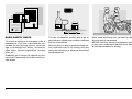
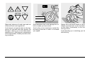
ETV mille Caponord
use+maintenancebook
aprilia part# 8104310
© 2001 aprilia s.p.a. - Noale (VE)
3!&%49 7!2.).'3
The following precautionary warnings are
used throughout this manual in order to
convey the following messages:
warning. When you find this
aSafety
symbol on the vehicle or in the
manual, be careful to the potential risk
of personal injury. Non-compliance with
the indications given in the messages
preceded by this symbol may result in
grave risks for your and other people’s
safety and for the vehicle!
First edition: february 2001
Reprint:
aWARNING
Indicates a potential hazard which may
result in serious injury or even death.
aCAUTION
Produced and printed by:
editing division
Soave (VERONA) - Italy
Tel. +39 - 045 76 11 911
Fax +39 - 045 76 12 241
E-mail: [email protected]
www.stp.it
On behalf of:
aprilia s.p.a.
via G. Galilei, 1 - 30033 Noale (VE) - Italy
Tel. +39 - 041 58 29 111
Fax +39 - 041 44 10 54
www.aprilia.com
2
use and maintenance ETV mille Caponord
Indicates a potential hazard which may
result in minor personal injury or damage to the vehicle.
NOTE The word “NOTE” in this manual
precedes important information or instructions.
4%#(.)#!, ).&/2-!4)/.
(
The operations preceded by this
symbol must be repeated also on
the opposite side of the vehicle.
If not expressly indicated otherwise, for the
reassembly of the units repeat the disassembly operations in reverse order.
The terms “right” and “left” are referred to
the rider seated on the vehicle in the normal riding position.
7!2.).'3 02%#!54)/.3 '%.%2!, !$6)#%
Before starting the engine, carefully read
this manual and in particular the section
“SAFE DRIVE”.
Your and other people’s safety depends
not only on your quickness of reflexes and
on your agility, but also on what you know
about the vehicle, on its efficiency and on
your knowledge of the basic information for
“SAFE DRIVE”. Therefore, get a thorough
knowledge of the vehicle, in such a way as
to be able to drive in the traffic safely.
NOTE Keep a stock of one bulb per type
with the vehicle (see technical data).
NOTE This manual must be considered
as an integral part of the vehicle and must
always accompany it, even in case of resale.
aprilia has carried out this manual with the
maximum attention, in order to supply the
user with correct and updated information.
However, since aprilia constantly improves the design of its products, there
may be slight discrepancies between the
characteristics of your vehicle and those
described in this manual. For any clarification concerning the information contained
in this manual, do not hesitate to contact
your aprilia Official Dealer.
For control and repair operations not expressly described in this publication, for the
purchase of aprilia genuine spare parts,
accessories and other products, as well as
for specific advice, contact exclusively
aprilia Official Dealers and Service Centers, which guarantee prompt and accurate
assistance.
Thank you for choosing aprilia. We wish
you a nice ride.
All rights as to electronic storage, reproduction and total or partial adaptation, with
any means, are reserved for all Countries.
NOTE In
some countries the antipollution and noise regulations in force require
periodical inspections.
The user of the vehicle in these countries
must:
– contact an aprilia Official Dealer to have
the non-homologated components replaced with others homologated for use
in the country in question;
– carry out the required periodical inspections.
NOTE Soon
after purchasing the vehicle, write down the identification data indicated on the SPARE PARTS IDENTIFICATION LABEL in the table here below. This
label is positioned on the frame, under the
saddle; to read it, it is necessary to remove
the saddle, see p. 78 (REMOVING THE
RIDER SADDLE).
These data indicate:
– YEAR = year of manufacture (Y, 1, 2, ...);
– I.M. = modification code (A, B, C, ...);
– COUNTRY CODES = homologation country (I, UK, A, ...).
In this manual the various versions are indicated by the following symbols:
e automatic light switching version
(Automatic Switch-on Device)
m optional
o catalytic version
VERSION:
I Italy
S Singapore
U
s Slovenia
United Kingdom
a Austria
i Israel
p
¬ South Korea
Portugal
F Finland
M Malaysia
B Belgium
c Chile
d Germany
H Croatia
f
A Australia
France
E Spain
u United States of
G
Ä Brazil
Greece
America
O Holland
R South Africa
Y Switzerland
n New Zealand
D Denmark
C Canada
J
Japan
and are to be supplied to the aprilia Official
Dealer as reference data for the purchase
of spare parts or specific accessories of
the model you have acquired.
use and maintenance ETV mille Caponord
3
4!",% /& #/.4%.43
SAFE DRIVE
BASIC SAFETY RULES ...................................... 6
CLOTHING .......................................................... 9
ACCESSORIES ................................................. 10
LOAD ................................................................. 10
ARRANGEMENT OF THE MAIN ELEMENTS ....... 12
ARRANGEMENT OF THE
INSTRUMENTS/CONTROLS .................................. 14
INSTRUMENTS AND INDICATORS ....................... 15
INSTRUMENTS AND INDICATORS TABLE ..... 16
SETTING BUTTONS ......................................... 20
MAIN INDEPENDENT CONTROLS ........................ 22
CONTROLS ON THE LEFT PART OF THE
HANDLEBAR ..................................................... 22
CONTROLS ON THE RIGHT PART OF THE
HANDLEBAR ..................................................... 23
IGNITION SWITCH ............................................ 24
STEERING LOCK .............................................. 25
PARKING LIGHTS ............................................. 25
AUXILIARY EQUIPMENT ....................................... 26
UNLOCKING/LOCKING THE
PASSENGER SEAT .......................................... 26
UNLOCKING/LOCKING THE GLOVE/TOOL KIT
COMPARTMENT COVER ................................. 26
GLOVE/TOOL KIT COMPARTMENT ................ 27
SPECIAL TOOLS m ........................................ 28
OUTLET ............................................................. 28
ACCESSORIES ................................................. 28
MAIN COMPONENTS ............................................. 29
FUEL .................................................................. 29
BRAKE FLUID - recommendations .................... 30
DISC BRAKES ................................................... 31
FRONT BRAKE ................................................. 32
REAR BRAKE .................................................... 34
CLUTCH FLUID - recommendations ................. 35
CLUTCH ............................................................ 36
COOLANT .......................................................... 38
TYRES ............................................................... 40
ENGINE OIL ...................................................... 41
ADJUSTING THE FRONT BRAKE CONTROL
LEVER AND THE CLUTCH CONTROL LEVER 42
4
use and maintenance ETV mille Caponord
ADJUSTING THE REAR BRAKE CONTROL
LEVER CLEARANCE .......................................
AUTOMATIC LIGHT SWITCHING
VERSION e ....................................................
CATALYTIC SILENCER o .............................
EXHAUST SILENCER/EXHAUST TERMINAL .
INSTRUCTIONS FOR USE ....................................
GETTING ON AND OFF THE VEHICLE ..........
PRELIMINARY CHECKING OPERATIONS .....
PRELIMINARY CHECKING OPERATIONS .....
STARTING ........................................................
DEPARTURE AND DRIVE ...............................
RUNNING-IN .....................................................
STOPPING ........................................................
PARKING ..........................................................
POSITIONING THE VEHICLE ON THE STAND
SUGGESTIONS TO PREVENT THEFT ...........
MAINTENANCE .....................................................
REGULAR SERVICE INTERVALS CHART ......
IDENTIFICATION DATA ...................................
CHECKING THE ENGINE OIL LEVEL AND
TOPPING UP ....................................................
CHANGING THE ENGINE OIL AND THE OIL
FILTER ..............................................................
AIR CLEANER ..................................................
FRONT WHEEL ................................................
FRONT BRAKE CALIPERS ..............................
REAR WHEEL ..................................................
POSITIONING THE VEHICLE ON THE FRONT
SUPPORT STAND m .....................................
REMOVING THE OIL SUMP GUARD ..............
REMOVE THE LEFT FAIRING .........................
REMOVAL OF THE FUEL TANK ......................
REMOVING THE FUSE BOX COVER .............
REMOVING THE RIDER SADDLE ...................
REAR-VIEW MIRRORS ....................................
DRIVE CHAIN ...................................................
CHECKING THE STEERING ............................
CHECKING THE REAR FORK
FULCRUM AXIS ...............................................
INSPECTING THE FRONT AND REAR
SUSPENSIONS ................................................
42
43
43
43
44
44
46
47
48
51
54
55
55
56
58
58
60
62
63
64
66
68
70
71
74
75
75
76
78
78
79
80
82
82
83
FRONT SUSPENSION ..................................... 83
REAR SUSPENSION ........................................ 84
CHECKING THE BRAKE PAD WEAR .............. 86
IDLING ADJUSTMENT ..................................... 87
ADJUSTING THE ACCELERATOR
CONTROL ......................................................... 87
CHECKING THE STAND .................................. 88
SPARK PLUGS ................................................. 90
BATTERY .......................................................... 92
CHECKING AND CLEANING THE
TERMINALS ...................................................... 92
REMOVING THE BATTERY ............................. 93
CHECKING THE ELECTROLYTE LEVEL ........ 93
RECHARGING THE BATTERY ........................ 94
INSTALLING THE BATTERY ............................ 94
LONG INACTIVITY OF THE BATTERY ............ 95
CHECKING THE SWITCHES ........................... 95
AIR TEMPERATURE SENSOR CONTROL ..... 95
CHANGING THE FUSES .................................. 96
HORIZONTAL ADJUSTMENT OF THE
HEADLIGHT BEAM ........................................... 98
ADJUSTING THE VERTICAL HEADLIGHT
BEAM ................................................................ 98
DASHBOARD LIGHTING .................................. 99
BULBS ............................................................... 99
CHANGING THE HEADLIGHT BULBS .......... 100
CHANGING THE FRONT DIRECTION
INDICATOR BULBS ........................................ 101
CHANGING THE REAR DIRECTION
INDICATOR BULBS ........................................ 102
CHANGING THE REAR LIGHT BULB ............ 102
CHANGING THE NUMBER PLATE
BULB ............................................................... 103
TRANSPORT ........................................................ 104
CLEANING ........................................................... 104
LONG PERIODS OF INACTIVITY .................. 106
TECHNICAL DATA .............................................. 107
LUBRICANT CHART ....................................... 110
Importers .................................................. 112-113
WIRING DIAGRAM - ETV mille Caponord ...... 114
safe drive
"!3)# 3!&%49 25,%3
To drive the vehicle it is necessary to be in
possession of all the requirements prescribed by law (driving licence, minimum
age, psychophysical ability, insurance,
state taxes, vehicle registration, number
plate, etc.).
Gradually get to know the vehicle by driving it first in areas with low traffic and/or private areas.
6
use and maintenance ETV mille Caponord
The use of medicins, alcohol and drugs or
psychotropic substances notably increases
the risk of accidents.
Be sure that you are in good psychophysical conditions and fit for driving and pay
particular attention to physical weariness
and drowsiness.
Most road accidents are caused by the
driver’s lack of experience.
NEVER lend the vehicle to beginners and,
in any case, make sure that the driver has
all the requirements for driving.
Rigorously observe all road signs and national and local road regulations.
Avoid abrupt movements that can be dangerous for yourself and other people (for
example: rearing up on the back wheel,
speeding, etc.), and give due consideration
to the road surface, visibility and other driving conditions.
Avoid obstacles that could damage the vehicle or make you lose control.
Avoid riding in the slipstream created by
preceding vehicles in order to increase
your speed.
Always drive with both hands on the handlebars and both feet on the footrests (or
on the rider’s footboards), in the correct
driving posture.
Avoid standing up or stretching your limbs
while driving.
use and maintenance ETV mille Caponord
7
OIL
The driver should pay attention and avoid
distractions caused by people, things and
movements (never smoke, eat, drink, read,
etc.) while driving.
8
use and maintenance ETV mille Caponord
COOLER
Use only the vehicle’s specific fuels and lubricants indicated in the “LUBRICANT
CHART”; check all oil, fuel and coolant levels regularly.
If the vehicle has been involved in an accident, make sure that no damage has occurred to the control levers, pipes, wires,
braking system and vital parts.
If necessary, have the vehicle inspected by
an aprilia Official Dealer who should carefully check the frame, handlebars, suspensions, safety parts and all the devices that
you cannot check by yourself.
Always remember to report any malfunction to the technicians to help them in their
work.
Never use the vehicle when the amount of
damage it has suffered endangers your
safety.
ONLY ORIGINALS
A12
345
Never change the position, inclination or
colour of: number plate, direction indicators, lights and horns.
Any modification of the vehicle will result in
the invalidity of the guarantee.
Any modification of the vehicle and/or the
removal of original components can compromise vehicle performance levels and
safety or even make it illegal.
We recommend respecting all regulations
and national and local provisions regarding
the equipment of the vehicle.
In particular, avoid all modifications that increase the vehicle’s performance levels or
alter its original characteristics.
Never race with other vehicles.
Avoid off-road driving.
#,/4().'
Before starting, always wear a correctly
fastened crash helmet. Make sure that it is
homologated, in good shape, of the right
size and that the visor is clean.
Wear protective clothing, preferably in light
and/or reflecting colours. In this way you
will make yourself more visible to the other
drivers, thus notably reducing the risk of
being knocked down, and you will be more
protected in case of fall.
This clothing should be very tight-fitting
and fastened at the wrists and ankles;
strings, belts and ties should not be hanging loose; prevent these and other objects
from interfering with driving by getting entangled with moving parts or driving mechanisms.
use and maintenance ETV mille Caponord
9
Do not keep objects that can be dangerous
in case of fall, for example pointed objects
like keys, pens, glass vials etc. in your
pockets (the same recommendations also
apply to passengers).
10
use and maintenance ETV mille Caponord
!##%33/2)%3
The owner of the vehicle is responsible for
the choice, installation and use of any accessory.
Avoid installing accessories that cover
horns or lights or that could impair their
functions, limit the suspension stroke and
the steering angle, hamper the operation of
the controls and reduce the distance from
the ground and the angle of inclination in
turns.
Avoid using accessories that hamper access to the controls, since this can prolong
reaction times during an emergency.
Big fairings and windshields installed on
the vehicle may produce aerodynamic forces that affect the stability of the vehicle, especially when riding at high speed.
Make sure that the equipment is well fastened to the vehicle and not dangerous
during driving.
Do not install electrical devices and do not
modify those already existing to avoid electrical overloads, because the vehicle could
suddenly stop or there could be a dangerous current shortage in the horn and in the
lights.
aprilia recommends the use of genuine
accessories (aprilia genuine accessories).
,/!$
Be careful and moderate when loading
your luggage. Keep any luggage loaded as
close as possible to the center of gravity of
the vehicle and distribute the load uniformly on both sides, in order to reduce umbalance to the minimum. Furthermore, make
sure that the load is firmly secured to the
vehicle, especially during long trips.
KG!
Avoid hanging bulky, heavy and/or dangerous objects on the handlebars, mudguards
and forks, because the vehicle might respond more slowly in turns and its manoeuvrability could be unavoidably impaired.
Do not place bags that are too bulky on the
vehicle sides and do not ride with the crash
helmet, because they could hit people or
obstacles, making you lose control of the
vehicle.
Do not carry any bag if it is not tightly secured to the vehicle.
Do not carry bags which protrude too much
from the luggage-rack or which cover the
lights, horn or indicators.
Do not carry animals or children on the
glove compartment or on the luggage rack.
Do not exceed the maximum load allowed
for each side-bag.
When the vehicle is overloaded, its stability
and its manoeuvrability can be compromised.
use and maintenance ETV mille Caponord
11
!22!.'%-%.4 /& 4(% -!). %,%-%.43
+%9
1)
2)
3)
4)
Headlight
Left rear-view mirror
Clutch fluid reservoir
Ignition switch/steering
lock/parking lights
5) Engine oil tank cap
12
use and maintenance ETV mille Caponord
6)
7)
8)
9)
10)
11)
Saddle lock
Rider left footrest
Rider saddle
Battery
Passenger seat
Electronic unit
12) Rear fork
13) Drive chain
14) Passenger left footrest
(snapping, closed/open)
15) Centre stand m
16) Side stand
17)
18)
19)
20)
21)
22)
Shifting lever
Engine oil filter
Engine oil tank
Engine oil level
Horn
Left fairing
+%9
1)
2)
3)
4)
5)
Rear light
Glove/tool kit compartment
Main fuse carrier (30A)
Rear shock absorber
Fuel tank
6)
7)
8)
9)
10)
Air cleaner
Fuel tank filler cap
Front brake fluid tank
Right rear-view mirror
Secondary fuse carrier
(15A)
11)
12)
13)
14)
15)
16)
Air temperature sensor
Coolant expansion tank cap
Coolant expansion
Rear brake control lever
Rider right footrest
Rear brake pump
17) Rear brake fluid tank
18) Passenger right footrest
(snapping, closed/open)
use and maintenance ETV mille Caponord
13
!22!.'%-%.4 /& 4(% ).3425-%.43#/.42/,3
6
5
4
3
2
1
0
140160
120
180
100
200
Km/h
80
220
60
240
260
40
280
20
0
Km
7
7 8
6 A
9
10
11
12
T AIR
min-1
x1000
L
gal
SERVICE
8
C
F
TIME
EFI
MODE
SET
ENGINE
CONTROL
DIAGNOSIS
9
1
5
10
4
3
2
12
11
+%9
Ignition switch/steering lock/parking lights (2 - 1 - & - :)
Direction indicator switch (6)
Horn push button (*)
Dimmer switch (8 - 7)
High beam signaller push button (7)/LAP push button (multifunction)
6) Clutch lever
1)
2)
3)
4)
5)
14
use and maintenance ETV mille Caponord
7)
8)
9)
10)
11)
12)
Instruments and indicators
Front brake lever
Throttle grip
Engine stop switch (2 - 1)
Start push button (+)
Light switch (( - ' - •) (not provided for e)
).3425-%.43 !.$ ).$)#!4/23
4
3
5
EFI
2
1
4
5 6
3
100
80
200
40
8
8
10
T AIR
min -1
1
0
180
km/h
60
7
9
2
120 140
160
7
6
x1000
MAGNETI
MARELLI
SERVICE
220
0
C
F
240
20
km
11
12
TIME
EFI
MODE
ENGINE
SET
CONTROL
DIAGNOSIS
10
9
+%9
1)
2)
3)
4)
5)
6)
7)
Speedometer
Green direction indicator warning light LED (6)
Red engine oil pressure warning light LED (.)
Amber side stand down warning light LED (Æ)
Red diagnostic warning light LED (EFI)
Blue high beam warning light LED (7)
Amber low fuel warning light LED (-)
8) Right multifunction digital display (fuel level-air temperature coolant temperature - clock/injection system error codes)
9) SET and MODE programming buttons
10) Green neutral indicator warning light LED (/)
11) Revolution counter
12) Left digital display (odometer)
use and maintenance ETV mille Caponord
15
).3425-%.43 !.$ ).$)#!4/23 4!",%
aCAUTION
The switching km/mi °C/°F is set and fixed by APRILIA in the
vehicle production phase, according to the country of destination.
This setting cannot be modified successively.
Description
Direction indicator warning light LED
High beam warning light LED
Revolution counter rpm
NOTE Whenever the ignition switch is turned to position “2”,
all the LED warning lights, including the dashboard lighting
LEDs, come on on the dashboard for approximately three seconds, thus testing the correct operation of the LEDs.
Function
6 Blinks when the direction indicators are on.
7 Comes on when the high beam bulbs are on or when the headlight signaller is operated.
Indicates the number of revolutions of the engine per minute.
Never exceed the engine max. speed rate, see p. 54 (RUNNING-IN).
aCAUTION
Amber low fuel warning light LED
Comes on when the quantity of fuel left in the tank is about 4 ± 1 L.
In this case, top up as soon as possible, see p. 29 (FUEL).
Side stand down war warning light
LED
Æ Comes on when the side stand is down.
Engine oil pressure warning light
LED
Neutral indicator warning light LED
Comes on whenever the ignition switch is in position “2” and the engine is not running, thus
checking the functionality of the LED.
If the light LED does not come on in this phase, contact an aprilia Official Dealer.
.
If the engine oil pressure warning light LED “.” remains on after
aCAUTION
the start or comes on during the normal operation of the engine,
this means that the engine oil pressure in the circuit is insufficient.
In this case, stop the engine immediately and contact an APRILIA Official Dealer.
/ Comes on when the gear is in neutral.
Follow ã
16
use and maintenance ETV mille Caponord
Follow ã
Description
Diagnostic warning light LED
Function
Comes on for approximately three seconds whenever the ignition switch is turned to position
“2”, thus testing the correct operation of the LED.
If the diagnostic warning light LED “EFI” comes on and blinks
aCAUTION
EFI
when the engine is started or starts blinking during the normal
operation of the engine, this means that the electronic unit has detected an anomaly. In
many cases, the engine keeps running with reduced performance levels; immediately
contact an APRILIA Official Dealer.
Speedometer (km/h)
It indicates the driving speed.
Digital display
Odometer (km - mi)
(left side)
Indicates the partial or total number of kilometres (miles) covered.
Multifunction
digital display Fuel level indicator
(right side)
Indicates the fuel level in the tank.
The fuel quantity is shown by the indicator range (analog display).
When the fuel tank is full, the indicator range is completely on.
As the fuel level decreases, the marked area of the indicator range decreases
accordingly.
When no segment of the indicator range is on and the low fuel warning light
- LED blinks, this means that the quantity of fuel left in the tank amounts to less
than 5 ± 1 L.
In this case, top up as soon as possible, see p. 29 (FUEL).
When no segment of the indicator range is on, the
aCAUTION
numerical display blinks indicating “” and the
low fuel warning light LED blinks, contact an APRILIA Official Dealer.
NOTE The digital sector is used to display the air temperature (T°AIR).
To alternate the
data displayed,
see p. 20 (SETTING BUTTONS).
Follow ã
use and maintenance ETV mille Caponord
17
Follow ã
Multifunction
Air temperature
digital display
indicator
(right side)
Displays the air temperature.
This temperature is displayed in the numerical sector (numerical display).
With temperatures under -20 °C (-4 °F) the writing “” is displayed; between
-20 °C (-68 °F) and 50 °C (122 °F) the exact temperature value is displayed;
over 50 °C (122 °F) the writing “” (“”) is displayed.
the digital display blinks indicating a tempeaWARNING When
rature equal to or lower than 3°C (37.4 °F), drive at
moderate speed, since there may be ice formation, and avoid abrupt
T°AIR brakings or manoeuvres that may cause loss of grip.
When the air temperature is equal to or lower than 3 °C (37.4 °F), the display
blinks indicating the temperature for ten seconds [even if in the meantime the
temperature increases and exceeds 3 °C (37.4 °F)].
If the temperature remains under 3 °C (37.4 °F), the procedure is repeated
every five minutes for three times.
When the digital display blinks showing the writing
aCAUTION
“BB” or the writing “”, contact an APRILIA Official Dealer.
To alternate the
data displayed,
see p. 20 (SETTING BUTTONS).
Follow ã
18
use and maintenance ETV mille Caponord
Follow ã
Indicates the temperature of the coolant in the engine, see p. 20 (SETTING
BUTTONS).
The temperature is indicated by the indicator range (analog display) and by
the value expressed in °C (°F) (digital display).
Up to 35 °C (97 °F) the writing “” is displayed.
aCAUTION
The switching on and off of the cooling fans does
not depend on the position of the ignition switch.
To lower the coolant temperature the cooling fans operate even when
the engine is not running and are switched off automatically.
Coolant temperature indicator (°C/°F)
)
aCAUTION
If the maximum allowed temperature (125°C or
257 °F) is exceeded, the engine may be seriou-
sly damaged.
If a temperature of 116 – 125 °C (241 – 257 °F) is displayed and the secondlast segment of the indicator range blinks, stop the engine, wait for the cooling
fans to be switched off and check the coolant level, see p. 38 (COOLANT).
If a temperature of 126 – 135 °C (259 – 275 °F) is displayed and the last two
segments of the indicator range blink, stop the vehicle and let the engine idle
for approximately two minutes, thus allowing the coolant to circulate regularly
in the system; then, press the engine stop switch to position “1” and check
the coolant level, see p. 38 (COOLANT). If the situation on the dashboard remains the same after the coolant level has been checked, do not start the
vehicle and contact an aprilia Official Dealer.
Multifunction
digital display
(right side)
Service operation indicator “SERVICE”
After the first 1000 km (625 mi) and successively every 7500 km (4600 mi),
the word “SERVICE” appears.
In this case contact an APRILIA Official Dealer,
aCAUTION
who will carry out the operations indicated in the
regular service intervals chart, see p. 60 (REGULAR SERVICE INTERVALS CHART).
Clock
Indicates the hour and minutes according to the presetting, see p. 20 (SETTING BUTTONS).
To alternate the
data displayed,
see p. 20 (SETTING BUTTONS).
use and maintenance ETV mille Caponord
19
2
4
EFI
5
1
T AIR
4
5 6
3
100
PU
SH
80
180
km/h
60
200
40
1
0
8
8
6
9
2
120 140
160
7
10
C
T AIR
min -1
x1000
9
MAGNETI
MARELLI
220
0
ENGINE
SET
CONTROL
DIAGNOSIS
C
240
20
TIME
EFI
MODE
km
TIME
ENGINE
MODE
3
3%44).' "544/.3
aWARNING
The operations described below must
be carried out with the vehicle at rest.
Performing these operations while the
vehicle is running may be cause of accidents.
NOTE
The following information is to be
considered as referred to the vehicle at
rest.
When the ignition key (1) is turned to position “2”, the following lights come on on
the dashboard within three seconds:
– all the warning lights LED;
– all the dashboard lighting LEDs;
– all the segments on the left display;
– all the segments and writings on the
right multifunction display;
– the pointers of the indicators move to the
bottom of the indicator range;
thus testing the operation of LEDs, writings, segments and instruments.
20
use and maintenance ETV mille Caponord
SET
CONTROL
DIAGNOSIS
7
After three seconds, the engine oil pressure warning light LED “.” (2) remains
on on the dashboard (and will remain on
until the engine is started) and the following will appear on the displays:
– total number of kilometres covered (3);
– fuel quantity (4);
– air temperature (5);
– coolant temperature (6) [up to 35 °C
(95°F) the writing “---” is displayed];
– hour and minutes (7).
ADJUSTING THE DASHBOARD
LIGHTING
It is possible to select three different levels
for the dashboard lighting: 100%; 60%;
25%.
For the adjustment, proceed as follows:
U Move the light switch (8) to position
“'”;
ì Bring the dimmer switch “8 - 7” (9)
to position “8”.
10
NOTE
Three seconds after the last selection, the button SET returns to the
switching mode total/partial kilometres
(miles) odometer.
U Turn the ignition switch (1) to position
“2” and, within three seconds, press the
button SET (10) in sequence, thus obtaining the three lighting levels.
U Select the desired lighting level.
SWITCHING FROM km/mi, °C/°F
aCAUTION
The switching km/mi, °C/°F is set and
fixed by APRILIA in the vehicle production phase, according to the country of
destination.
This setting cannot be modified successively.
T AIR
4
5 6
3
L
7
5
4
9
2
1
0
T AIR
8
km/h
C
10
C
km
TIME
ENGINE
TIME
MODE
ENGINE
MODE
2
SET
SET
CONTROL
DIAGNOSIS
CONTROL
DIAGNOSIS
1
3
1
SWITCHING FROM TOTAL TO PARTIAL
KILOMETRE (MILE) ODOMETER
Left display
U Press and release the button SET (1);
the relevant total partial or total kilometres (miles) covered will appear on the
display.
SETTING THE CLOCK (HOURS AND
MINUTES)
U To confirm the minute setting, press and
NOTE
NOTE
NOTE
NOTE
Whenever the ignition switch is
turned to position “2”, the display always
indicates the total number of kilometres
(miles) covered.
To set the partial kilometre (mile) odometer to zero, proceed as follows:
U Display the partial number of kilometres
covered, see above.
U Press the button SET (1) for more than
three seconds; the segments (2) are set
to zero.
The setting of the clock can be
carried out only with the vehicle at rest.
release the MODE (3) push button.
If the battery is removed, the
clock is set to zero.
U Press the MODE (3) push button for
more than three seconds, the segments
corresponding to the hours (4) will blink.
If the button SET (1) is pressed
and released, the data are changed one by
one; if the button SET (1) is kept pressed,
the data change scrolling quickly and cyclically.
U Press the SET (1) push button and se-
lect the desired hour.
U To confirm the time setting, press and re-
lease the button MODE (3), and the
minute segments (5) will blink.
U Press the SET (1) push button and select the desired minutes.
use and maintenance ETV mille Caponord
21
-!). ).$%0%.$%.4 #/.42/,3
4
#/.42/,3 /. 4(% ,%&4 0!24 /& 4(%
(!.$,%"!2
NOTE
The electrical parts work only when the ignition switch
is in position “2”.
3
1) HORN PUSH BUTTON (*)
The horn is activated when the push button is pressed.
2
1
2) DIRECTION INDICATOR SWITCH (6)
To indicate the turn to the left, move the switch to the left; to
indicate the turn to the right, move the switch to the right.
To turn off the direction indicator, press the switch.
3) DIMMER SWITCH (8 - 7)
When the light switch is in position “(”: if the dimmer switch
is in position “7”, the high beam comes on; while if it is in position “8”, the low beam comes on.
3) DIMMER SWITCH (8 - 7) e
When it is in position “8” the parking lights, the dashboard
light and the low beam are always on.
When it is in position “7”, the high beam comes on.
4) HIGH BEAM SIGNALLING PUSH BUTTON (7)
It makes it possible to use the high beam for signalling to
forthcoming vehicles while overtaking and in case of peril
and/or emergency.
The high beam blinking is operated by pressing the push button, independently of the position of the light switch (( - '
- •).
NOTE
button.
22
use and maintenance ETV mille Caponord
To disconnect the high beam blinking, release the push
#/.42/,3 /. 4(% 2)'(4 0!24 /& 4(%
(!.$,%"!2
1
NOTE
The electrical parts work only when the ignition switch
is in position “2”.
A
PU
SH
1) ENGINE STOP SWITCH (2 - 1)
aWARNING
Do not operate the engine stop switch “2 - 1” in running
conditions.
This is a safety or emergency switch.
With the switch pressed in position “2”, it is possible to start
the engine; when the switch is pressed to position “1”, the
engine stops.
aCAUTION
To stop the vehicle, use exclusively the ignition switch (A).
Leave the engine stop switch (1) in position “2” and use it
only in case of emergency.
aCAUTION
2
3
3) START PUSH BUTTON (+)
When the start push button “+” is pressed, the starter makes
the engine run. For the starting, see p. 48 (STARTING).
With stopped engine and ignition switch in position “2”, the
battery may discharge.
If the engine stop switch must be used (1), immediately afterwards turn the ignition switch (A) to position “1”.
2) LIGHT SWITCH (( - ' - •) (not provided for e)
When the light switch is in position “•”, the lights are off; when
the switch is in position “'”, the parking lights and the dashboard light are on; when the switch is in position “(”, the
parking lights, the dashboard light and the low beam are on.
The high beam can be operated by means of the dimmer
switch.
use and maintenance ETV mille Caponord
23
Position
1
Steering
lock
2
3
The ignition switch (1) is positioned on the
upper plate of the steering column.
Two keys are supplied together with the
vehicle (one spare key).
NOTE
Do not keep the spare key on the
vehicle.
24
use and maintenance ETV mille Caponord
It is possible
The steering is loc- to remove the
key.
ked. It is
neither possible to start
the engine,
nor to switch
on the
lights.
The engine It is not possiand the
ble to remove
lights can be the key.
switched on.
PU
SH
The key operates the ignition
switch/steering lock, the fuel tank lock (2)
and the passenger seat lock (3).
Key removal
Neither the It is possible
engine, nor to remove the
the lights
key.
can be
switched on.
)'.)4)/. 37)4#(
NOTE
Function
The parking It is possible
lights are
to remove the
on.
key.
Z AD I
1
34%%2).' ,/#+
aWARNING
Never turn the key to position “&” in
running conditions, in order to avoid
losing control of the vehicle.
OPERATION
To lock the steering:
U Turn the handlebar completely leftwards.
U Turn the key to position “1”.
U Press the key and rotate it to position “&”.
NOTE
If it is necessary to switch on the
parking lights, see p. 25 (PARKING
LIGHTS).
U Extract the key.
PU
SH
1
PU
SH
1
0!2+).' ,)'(43
The vehicle is provided with front and rear
parking lights. Even if it is always advisable
to park the vehicle in the appropriate parking areas and in any case in illuminated
places, the parking lights are very useful
when it is necessary to park the vehicle in a
dark or badly illuminated area, or in any
case when the vehicle must be visible.
aCAUTION
Do not leave the parking lights on for
long periods, in order to avoid the wear
of the battery due to the current consumption required by the lights. The
complete wear of the battery makes it
impossible to start the vehicle.
OPERATION
To switch on the parking lights, proceed
as follows:
U Lock the steering without extracting the
key (1), see p. 25 (STEERING LOCK).
U Turn the key (1) to position “:” (PARK-
ING).
U Make sure that both parking lights (front
and rear) are on and operate correctly.
U Remove the key (1).
use and maintenance ETV mille Caponord
25
!58),)!29 %15)0-%.4
5.,/#+).',/#+).' 4(%
0!33%.'%2 3%!4
U Position the vehicle on the stand, see p.
56 (POSITIONING THE VEHICLE ON
THE STAND).
U Introduce the key (1) in the seat lock.
U Rotate the key (1) clockwise, lift and
withdraw the seat (2) from behind.
NOTE
To lock the seat (2), proceed as follows:
NOTE
Before lowering and locking the
seat (2), make sure that you have not left
the key in the glove/tool kit compartment.
U Insert the two front couplings (4) in the
relevant seats (5).
U Lower and press the passenger seat (2),
making the lock snap.
The glove/tool kit compartment is
positioned under the passenger seat.
aWARNING
To reach it, proceed as follows:
U Remove the glove/tool kit compartment
cover (3).
Before leaving, make sure that the seat
(2) is properly locked.
26
use and maintenance ETV mille Caponord
5.,/#+).',/#+).' 4(%
',/6%4//, +)4 #/-0!24-%.4
#/6%2
If a larger surface for the luggage is needed, when the rider travels alone the passenger seat can be removed. To carry out
this operation, it is necessary to lock the
glove/tool kit compartment cover (3).
In this case:
U Remove the passenger seat, see p. 26
(UNLOCKING/LOCKING THE PASSENGER SEAT).
U Remove the lock coupling (6) from its
seat.
U Insert the lock coupling (6) and fit it correctly in the appropriate seat (7) on the
glove/tool kit compartment cover (see
figure).
U Correctly position the glove/tool kit compartment cover (3) in its seat.
10
6
11
9
7
14
6
12
15
13
U Lower and press the glove/tool kit com-
partment cover (3), making the lock
snap.
Maximum allowed weight: 9 kg.
aWARNING
The luggage must not be excessively
bulky and it must be firmly anchored to
the passenger grab rails.
',/6%4//, +)4 #/-0!24-%.4
To reach the glove/tool kit compartment,
proceed as follows:
U Remove the saddle, see p. 26 (UNLOCKI N G / L O C KI NG T HE PA SS E NG ER
SEAT).
The tool kit (8) includes:
– 2.5 – 3 – 4 – 5 – 6 mm bent hexagon
spanners (9);
– 8 – 10 mm double fork spanner (10);
– 13 – 14 mm double fork spanner (11);
– 26 mm simple box spanner (12);
– extension for simple box spanners (13);
– 6 – 7 mm double socket spanner (14);
– 8 – 10 mm double socket spanner (15);
– 16 mm socket spanner for spark plug
(16);
– double-ended, cross-/cut-headed screwdriver (17);
– tool case (18);
16
18
17
Maximum allowed weight: 1.5 kg.
use and maintenance ETV mille Caponord
27
1
30%#)!, 4//,3 m
To perform some specific operations, it is
advisable to use the following special tools
(to be requested to an aprilia Official Dealer):
Tool
2
Operations
Front support stand (1), see p. Front wheel di74 (POSITIONING THE VEHI- sassembly.
CLE ON THE FRONT SUPPORT STAND m).
/54,%4
This vehicle is provided with an outlet (2)
for plugs with 20 mm diameter.
Do not connect any electrical equipment with
electrical input over 180 W or voltage different from 12 V to the outlet.
aWARNING
Do not use the outlet while the vehicle
is running, since the plug may come off
and fall on the moving parts of the vehicle.
!##%33/2)%3
The vehicle may be equipped with the following accessories (to be requested to the
aprilia Official Dealer):
– centre stand m;
– side bags m;
– bag on the tank m;
– rear case m.
28
use and maintenance ETV mille Caponord
-!). #/-0/.%.43
&5%,
aWARNING
The fuel used for internal combustion
engines is extremely inflammable and
in particular conditions it can become
explosive.
It is important to carry out the refuelling
and the maintenance operations in a
well-ventilated area, with the engine off.
Do not smoke while refuelling or near
fuel vapours, in any case avoid any contact with naked flames, sparks and any
other heat source to prevent the fuel
from catching fire or from exploding.
Further, prevent fuel from flowing out of
the fuel filler, as it could catch fire when
getting in contact with the red-hot surfaces of the engine.
In case some fuel has accidentally been
spilt, make sure that the area has completely dried and before starting the vehicle verify that there is no fuel inside
the fuel filler neck.
Since petrol expands under the heat of
the sun and due to the effects of sun radiation, never fill the tank to the brim.
Screw the plug up carefully after refuelling. Avoid any contact of the fuel with
the skin and the inhalation of vapours;
do not swallow fuel or pour it from a receptacle into another by means of a
tube.
DO NOT DISPOSE OF FUEL IN THE ENVIRONMENT.
KEEP AWAY FROM CHILDREN.
Use only premium grade unleaded petrol,
min. O.N. 95 (N.O.R.M.) and 85
(N.O.M.M.).
To refuel, proceed as follows:
U Raise the flap (1).
U Insert the key (2) in the tank plug lock
(3).
U Turn the key clockwise, pull and open
the fuel flap.
FUEL TANK CAPACITY (reserve included): 25 L
TANK RESERVE: 5 ± 1 L
aCAUTION
Do not put additives or other substances into the fuel.
If you use a funnel or other similar
items, make sure that they are perfectly
clean.
aWARNING
1
MAX
MAX
3
2
After refuelling:
NOTE
The cap can be closed only when
the key (2) is inserted.
U With inserted key (2), close the cap by
pressing it.
aWARNING
Make sure that the cap is properly
closed.
U Withdraw the key (2).
U Close the flap (1).
Do not fill the tank completely; the maximum fuel level must remain below the
lower edge of the filler neck (see figure).
U Refuel.
use and maintenance ETV mille Caponord
29
NOTE
This vehicle is provided with front
and rear disc brakes, with separate hydraulic circuits.
aWARNING
aWARNING
Make sure that the brake discs are neither oily nor greasy, especially after
maintenance or checking operations.
The following information refers to a single
braking system, but is valid for both.
Check that the brake cables are neither
twisted nor worn out.
Carefully wash the parts of your body
that get in contact with the liquid. Consult a doctor or an oculist if the liquid
gets in contact with your eyes.
aWARNING
Prevent water or dust from accidentally
getting into the circuit.
"2!+% &,5)$ RECOMMENDATIONS
Sudden resistance or clearance problems on the brake lever may be due to
troubles in the hydraulic system.
For any doubt regarding the perfect
functioning of the braking system and
in case you are not able to carry out the
usual checking operations, contact
your APRILIA Official Dealer.
30
use and maintenance ETV mille Caponord
In case maintenance operations are to
be performed on the hydraulic circuit, it
is advisable to use latex gloves.
If the brake fluid gets in contact with the
skin or the eyes, it can cause serious irritations.
DO NOT DISPOSE OF THE FLUID IN
THE ENVIRONMENT.
KEEP AWAY FROM CHILDREN.
aCAUTION
When using the brake fluid, take care
not to spill it on the plastic or painted
parts, since it can damage them.
$)3# "2!+%3
aWARNING
The brakes are the parts that most ensure your safety and for this reason
they must always be perfectly working;
check them before every trip.
A dirty disc soils the pads, with consequent reduction of the braking efficiency.
Dirty pads must be replaced, while dirty
discs must be cleaned with a high-quality degreaser.
The brake fluid must be changed every
two years by an APRILIA Official Dealer.
Use brake fluid of the type specified in
the lubricant chart, see p. 110 (LUBRICANT CHART).
NOTE
NOTE
The front braking system is with double
disc (right and left side).
The rear braking system is with single disc
(right side).
The following information refers to a single
braking system, but is valid for both.
When the disc pads wear out, the level of
the fluid decreases to automatically compensate for their wear.
The front brake reservoir is positioned on
the right part of the handlebar, near the
front brake lever coupling.
Have the brake discs checked by an aprilia Official Dealer after the first 1000 km
(625mi) and successively every 7500 km
(4687 mi).
Before departure, check the brake fluid level in the reservoirs, see p. 32 (FRONT
BRAKE), p. 34 (REAR BRAKE), and the
wear of the pads, see p. 86 (CHECKING
THE BRAKE PAD WEAR).
Have the brake fluid changed every two
years by an aprilia Official Dealer.
This vehicle is provided with disc
brakes with two, front and rear braking systems having separate hydraulic circuits.
The rear brake reservoir is positioned on
the right side of the vehicle, near the rear
brake control lever.
Perform the maintenance operations with doubled frequency if the vehicle
is used in rainy or dusty areas, on uneven
surfaces or on racetracks.
aWARNING
Do not use the vehicle if the braking
system leaks fluid.
use and maintenance ETV mille Caponord
31
3
2
2
1
5
MIN
4
1
&2/.4 "2!+%
CHECK
U Position the vehicle on the stand, see p.
56 (POSITIONING THE VEHICLE ON
THE STAND).
U Turn the handlebar partially rightwards,
so that the fluid contained in the brake
fluid tank is parallel to the edge of the
brake fluid tank (1) (see figure).
U Make sure that the fluid level exceeds
the “MIN” mark.
MIN= minimum level
If the fluid does not reach at least the “MIN”
mark:
aCAUTION
When the disc pads wear out, the level
of the fluid decreases progressively to
compensate for their wear.
32
use and maintenance ETV mille Caponord
U Check the brake pad wear, see p. 86
U Unscrew the two screws (2) of the brake
(CHECKING THE BRAKE PAD WEAR)
and the disc wear.
reservoir (1) by means of a short, crossheaded screwdriver.
If the pads and/or the disc do not need replacing, provide for topping up.
TOPPING UP
Carefully read p. 30 (BRAKE FLUID recommendations).
aCAUTION
The brake fluid may flow out of the tank.
Do not operate the front brake lever if
the screws (2) are loose or, most important, if the brake fluid tank cover has
been removed.
aCAUTION
Position a cloth under the brake reservoir, in case some fluid should be
spilled.
aWARNING
Avoid any prolonged exposure of the
brake fluid to the air.
The brake fluid is hygroscopic and
when in contact with the air it absorbs
its humidity.
Leave the brake fluid tank open ONLY
for the time necessary for topping up.
U Raise and remove the cover (3) together
with the screws (2).
U Remove the guide cover (4).
U Remove the gasket (5).
5 - 6 mm
6
1
aCAUTION
aCAUTION
In order not to spill the brake fluid while
topping up, do not shake the vehicle.
Do not put additives or other subtances
into the fluid.
If you use a funnel or other similar
items, make sure that they are perfectly
clean.
Do not exceed the “MAX” level while
topping up.
It is advisable to top up until reaching
the “MAX” level only with new pads.
Do not reach the “MAX” level with worn
out pads, since this will cause a fluid
outflow when the pads are changed.
NOTE
As a reference mark corresponding to the maximum level “MAX”, use the
notch (6) stamped inside the brake fluid
tank (1) and top up until reaching it.
U Put back the gasket (5) in its seat cor-
rectly.
U Put back the guide cover (4) correctly.
U Put back the cover (3).
U Screw and tighten the screws (2).
aWARNING
Check the braking efficiency.
In case of excessive stroke of the brake
lever or reduced efficiency of the braking system, contact an APRILIA Official
Dealer, since it may be necessary to
bleed the system.
NOTE
If no notch (6) is available, top up
leaving a space of 5 – 6 mm from the edge
of the brake fluid tank (1).
U Top up the reservoir (1) by adding brake
fluid, see p. 110 (LUBRICANT CHART),
until reaching the correct level.
use and maintenance ETV mille Caponord
33
aCAUTION
2
4
MIN
2
MIN
5
3
1
2%!2 "2!+%
CHECK
U Keep the vehicle in vertical position, so
that the fluid contained in the tank (1) is
parallel to the plug (2).
U Make sure that the fluid level exceeds
the “MIN” mark.
MIN= minimum level
MAX= maximum level
If the fluid does not reach at least the “MIN”
mark:
aCAUTION
When the disc pads wear out, the level
of the fluid decreases progressively to
compensate for their wear.
U Check the brake pad wear, see p. 86
(CHECKING THE BRAKE PAD WEAR)
and the disc wear.
If the pads and/or the disc do not need replacing, provide for topping up.
34
use and maintenance ETV mille Caponord
1
TOPPING UP
Carefully read p. 30 (BRAKE FLUID recommendations).
aCAUTION
The brake fluid may flow out of the tank.
Do not operate the rear brake lever if the
brake fluid tank plug is loose or has
been removed.
aWARNING
Avoid any prolonged exposure of the
brake fluid to the air.
The brake fluid is hygroscopic and
when in contact with the air it absorbs
its humidity.
Leave the brake fluid tank open ONLY
for the time necessary for topping up.
U Unscrew and remove the screw (3), tak-
ing the nut.
U Remove the clip (4).
U Unscrew and remove the plug (2).
In order not to spill the brake fluid while
topping up, keep the fluid in the tank
parallel to the tank rim (in horizontal position).
Do not put additives or other subtances
into the fluid.
If you use a funnel or other similar
items, make sure that they are perfectly
clean.
U Remove the gasket (5).
U Top up the reservoir (1) by adding brake
fluid, see p. 110 (LUBRICANT CHART),
until reaching the correct level included
between the “MIN” and “MAX” marks”.
aCAUTION
It is advisable to top up until reaching
the “MAX” level only with new pads. Do
not reach the “MAX” level with worn out
pads, since this will cause a fluid outflow
when the pads are changed.
Check the braking efficiency.
In case of excessive stroke of the brake
lever or reduced efficiency of the braking system, contact an APRILIA Official
Dealer, since it may be necessary to
bleed the system.
aCAUTION
Make sure that the cable is neither
twisted nor worn out.
Prevent water or dust from accidentally
getting into the circuit.
In case maintenance operations are to
be performed on the hydraulic circuit, it
is advisable to use latex gloves.
#,54#( &,5)$ RECOMMENDATIONS
NOTE
This vehicle is provided with hydraulic clutch control.
aCAUTION
Sudden resistance or clearance problems on the clutch lever may be due to
troubles in the hydraulic system.
For any doubt regarding the perfect
functioning of the system and in case
you are not able to carry out the usual
checking operations, contact your
APRILIA Official Dealer.
If the fluid gets in contact with the skin
or the eyes, it can cause serious irritations.
Carefully wash the parts of your body
that get in contact with the liquid. Consult a doctor or an oculist if the liquid
gets in contact with your eyes.
DO NOT DISPOSE OF THE FLUID IN
THE ENVIRONMENT.
KEEP AWAY FROM CHILDREN.
When using the fluid, take care not to
spill it on the plastic and painted parts,
since it damages them.
The clutch control fluid must be
changed every two years by an APRILIA
Official Dealer.
Use fluid of the type specified in the lubricant chart, see p. 110 (LUBRICANT
CHART).
The clutch fluid reservoir is positioned on
the left part of the handlebar, near the
clutch control lever coupling.
NOTE
Perform the maintenance operations with doubled frequency if the vehicle
is used in rainy or dusty areas, on uneven
surfaces or on racetracks.
Before departure, check the fluid level in
the tank, see p. 36 (CLUTCH); have it
changed by an aprilia Official Dealer every
two years.
aWARNING
Do not use the vehicle if you notice fluid
leakages from the clutch control system.
use and maintenance ETV mille Caponord
35
2
1
MIN
2
#,54#(
NOTE
Perform the maintenance operations with doubled frequency if the vehicle
is used in rainy or dusty areas, on uneven
surfaces or on racetracks.
Have the clutch checked by an aprilia Official Dealer every 7500 km (4687 mi).
NOTE
The engine is provided with an
hydraulic control clutch, aided by the PPC
(Pneumatic Power Clutch) exclusive patented system, which avoids the bouncing
of the rear wheel.
CHECK
U Position the vehicle on the stand, see p.
56 (POSITIONING THE VEHICLE ON
THE STAND).
U Turn the handlebar partially rightwards,
so that the fluid contained in the clutch
fluid tank is parallel to the edge of the
clutch fluid tank (1) (see figure).
U Make sure that the fluid level exceeds
the “MIN” mark.
MIN= minimum level
U If the fluid does not reach the “MIN”
mark, provide for topping up.
TOPPING UP
Carefully read p. 35 (CLUTCH FLUID recommendations).
aCAUTION
The fluid may flow out. Do not operate
the clutch control lever if the reservoir
plug is loose or has been removed.
aWARNING
Avoid any prolonged exposure of the
clutch fluid to the air.
The clutch fluid is hygroscopic and
when in contact with the air it absorbs
its humidity.
Leave the clutch fluid tank open ONLY
for the time necessary for topping up.
aCAUTION
Position a cloth under the brake reservoir, in case some fluid should be
spilled.
U Using a short, cross-tip screwdriver, un-
screw the two screws (2) of the clutch
fluid tank (1).
36
use and maintenance ETV mille Caponord
3
2
4
2
1
5
aCAUTION
Do not shake the vehicle, in order not to
spill fluid while topping up.
Do not put additives or other subtances
into the fluid.
If you use a funnel or other similar
items, make sure that they are perfectly
clean.
U Raise and remove the cover (3) together
with the screws (2).
U Remove the gasket (4).
NOTE
In order to reach the “MAX” level,
top up until covering the glass (5) completely, with the clutch fluid reservoir rim parallel
to the ground.
aCAUTION
Do not exceed the “MAX” level while
topping up.
U Put back the gasket (4) in its seat cor-
rectly.
U Put back the cover (3).
U Screw and tighten the screws (2).
aWARNING
Check the clutch efficiency.
If the stroke of the clutch control lever
is excessive or if the clutch system is
not efficient, contact your APRILIA Official Dealer, since it may be necessary to
bleed the system.
U Top up the reservoir (1) by adding clutch
fluid, see p. 110 (LUBRICANT CHART),
until reaching the correct level.
use and maintenance ETV mille Caponord
37
#//,!.4
aCAUTION
1
Do not use the vehicle if the coolant is
below the minimum prescribed level
(LOW).
NOTE
Perform the maintenance operations with doubled frequency if the vehicle
is used in rainy or dusty areas, on uneven
surfaces or on racetracks.
Before departure, check the coolant level,
see p. 39 (CHECKING AND TOPPING
UP); have the coolant changed every two
years: for this operation, contact an aprilia
Official Dealer.
aWARNING
The coolant is noxious: do not swallow
it; if the coolant gets in contact with the
skin or the eyes, it can cause serious irritations.
If the fluid gets in contact with your skin
or eyes, rinse with plenty of water and
consult a doctor. If it is swallowed, induce vomit, rinse mouth and throat with
plenty of water and consult a doctor
without delay.
KEEP AWAY FROM CHILDREN.
DO NOT DISPOSE OF THE FLUID IN
THE ENVIRONMENT.
Be careful not to spill the coolant on the
red-hot parts of the engine: it may catch
fire and send out invisible flames.
38
use and maintenance ETV mille Caponord
In case any maintenance operation
should be required, it is advisable to
use latex gloves.
aCAUTION
Have the pads changed by your APRILIA
Official Dealer.
The coolant is composed of 50% water and
50% antifreeze.
This mixture is ideal for most running temperatures and ensures good protection
against corrosion.
It is advisable to keep the same mixture
also in the hot season, since in this way
losses due to evaporation are reduced and
it is not necessary to top up very frequently.
The mineral salt deposits left in the radiator
by evaporated water are thus reduced and
the efficiency of the cooling system remains unchanged.
If the outdoor temperature is below 0°,
check the cooling circuit frequently and if
necessary increase the antifreeze concentration (up to maximum 60%).
For the cooling solution use distilled water,
in order not to damage the engine.
aWARNING
Do not remove the expansion tank plug
(1) when the engine is hot, since the
coolant is under pressure and its temperature is high.
If it gets in contact with the skin or with
clothes it may cause severe burns
and/or damage.
2
1
1
FULL
LOW
CHECKING AND TOPPING UP
aWARNING
Check the coolant level and top up the
expansion tank with cold engine.
U Stop the engine and wait until it has
cooled down.
U Keep the vehicle in vertical position, with
the two wheels resting on the ground.
U Make sure that the coolant contained in
the expansion tank (2) is included between the “FULL” and “LOW” marks, by
checking through the appropriate slot on
the right fairing”.
FULL = maximum level
LOW = minimum level
If not, proceed as follows:
U Top up the expansion tank by adding
U Unscrew and remove the filling cap (1).
coolan t, se e p. 11 0 (LUBRICANT
CHART), until this almost reaches the
“FULL” level. Do not exceed this level,
otherwise the fluid will flow out while the
engine is running.
U Put back the filling cap (1).
aWARNING
The coolant is noxious: do not swallow
it; if the coolant gets in contact with the
skin or the eyes, it can cause serious irritations.
Do not use your fingers or any other object to check if there is enough coolant.
aCAUTION
Do not put additives or other subtances
into the fluid.
If you use a funnel or other similar
items, make sure that they are perfectly
clean.
aCAUTION
In case of excessive consumption of
coolant and in case the tank remains
empty, make sure that there are no
leaks in the circuit. Have it repaired by
an APRILIA Official Dealer.
use and maintenance ETV mille Caponord
39
492%3
After repairing a tyre, have the wheels
balanced.
This vehicle is provided with tubeless tyres.
aWARNING
NOTE
Perform the maintenance operations with doubled frequency if the vehicle
is used in rainy or dusty areas, on uneven
surfaces or on racetracks.
aWARNING
1
Check the inflation pressure at room
temperature every two weeks.
Check the conditions of the tyres and
the inflation pressure at room temperature every 1000 km (625 mi), see p. 107
(TECHNICAL DATA).
aWARNING
Periodically check the tyre inflation
pressure at room temperature, see p.
107 (TECHNICAL DATA).
If the tyres are hot, the measurement is
not correct.
Carry out the measurement especially
before and after long rides.
If the inflation pressure is too high, the
ground unevenness cannot be dampened and is therefore transmitted to the
handlebar, thus compromising the driving comfort and reducing the road holding during turns.
If, on the contrary, the inflation pressure
is too low, the tyre sides (1) are under
greater stress and the tyre itself may
slip on the rim or it may become loose,
with consequent loss of control of the
vehicle.
40
use and maintenance ETV mille Caponord
In case of sudden braking the tyres
could even come off the rims.
Further, the vehicle could skid while
turning.
aWARNING
Check the surface and the wear of the
tyres, since tyres in bad conditions can
impair both the grip and the controllability of the vehicle.
Some types of tyres homologated for
this vehicle are provided with wear indicators.
There are several kinds of wear indicators. For more information on how to
check the wear, contact your Dealer.
Visually check if the tyres are worn and
in this case have them changed.
Change the tyre when it is worn out or
in case of puncture on the tread side, if
the puncture is larger than 5 mm.
The tyres must be replaced with other
tyres of the type and model recommended by the manufacturer, see p. 107
(TECHNICAL DATA); the use of tyres
different from those prescribed may adversely affect the manoeuvrability of the
vehicle.
Do not install tyres with air tube on rims
for tubeless tyres and viceversa.
Make sure that the inflation valves (2)
always have their sealing caps on, to
prevent the tyres from suddenly going
flat.
Change, repair, maintenance and balancing operations are very important
and therefore they must be performed
by qualified technicians with appropriate tools.
aWARNING
For this reason, it is advisable to have
the above mentioned operations carried
out by an APRILIA Official Dealer or by a
qualified tyre repairer.
If the tyres are new, they may still be
covered with a slippery film: drive carefully for the first miles. Do not oil the
tyres with unsuitable fluids. If the tyres
are old, even if not completely worn out,
they may become hard and may not ensure good road holding.
In this case, replace them.
%.').% /),
aWARNING
Engine oil may cause serious damage
to the skin if handled daily and for long
periods.
Wash your hands carefully after use.
3
KEEP AWAY FROM CHILDREN.
2
MINIMUM TREAD DEPTH LIMIT (3):
front and rear 2 mm and in any case not
less than prescribed by the regulations in
force in the country where the vehicle is
used.
aCAUTION
Be particularly careful when installing/removing the tyres, in order to avoid
scratching or damaging the rims with
the vice.
DO NOT DISPOSE OF THE OIL IN THE
ENVIRONMENT.
Put it in a sealed container and take it to
the filling station where you usually buy
it or to an oil salvage center.
In case any maintenance operation
should be required, it is advisable to
use latex gloves.
aCAUTION
If the engine oil pressure warning light
LED “.” comes on during the normal
operation of the engine, this means that
the engine oil pressure in the circuit is
insufficient.
In this case, check the engine oil level,
see p. 63 (CHECKING THE ENGINE OIL
LEVEL AND TOPPING UP); if the level
isn’t correct, stop the engine immediately and contact an APRILIA Official
Dealer.
aCAUTION
Proceed with care.
Do not spill the oil!
Take care not to smear any component,
the area in which you are working and
the surrounding area. Carefully remove
any trace of oil.
In case of leakages or malfunctions,
contact an APRILIA Official Dealer.
Periodically check the engine oil level, see
p. 63 (CHECKING THE ENGINE OIL LEVEL AND TOPPING UP).
For the engine oil change, see p. 60 (REGULAR SERVICE INTERVALS CHART)
and p. 64 (CHANGING THE ENGINE OIL
AND THE OIL FILTER).
NOTE
Use high-quality 15W – 50 oil,
see p. 110 (LUBRICANT CHART).
use and maintenance ETV mille Caponord
41
3
2
3
1
1
4
7
1
8
5
6
4m
m
2
3
4
4
2
!$*534).' 4(% &2/.4 "2!+%
#/.42/, ,%6%2 !.$ 4(%
#,54#( #/.42/, ,%6%2
It is possible to adjust the distance between the lever (1) end and the grip (2), by
rotating the adjuster (3).
The positions “1” and “4” correspond to an
approximate distance of 105 and 85 mm,
respectively, between the lever end and
the grip.
The positions “2” and “3” correspond to intermediate distances.
~Push the control lever (1) forward and
rotate the adjuster (3) until the desired
number is positioned in correspondence
with the reference arrow.
42
use and maintenance ETV mille Caponord
!$*534).' 4(% 2%!2 "2!+%
#/.42/, ,%6%2 #,%!2!.#%
The brake control lever is positioned ergonomically during the assembly of the vehicle.
If necessary, it is possible to adjust the
brake control lever clearance:
U Loosen the lock nut (4).
U Screw the brake adjuster (5) completely.
U Screw the lock nut (6) completely on the
pump control rod (7).
U Screw the pump control rod (7) completely, then unscrew it by giving 3 – 4
turns.
U Screw the brake adjuster (5) until the
brake pedal reaches the desired height.
U Lock the brake adjuster (5) by means of
the lock nut (4).
U Unscrew the pump control rod (7) and
bring it in contact with the pump piston.
U Screw the rod in order to ensure a minimum clearance of 0.5 – 1 mm between
the pump control rod (7) and the pump
piston.
aCAUTION
Make sure that there is a certain idle
stroke in the movement of the lever (8),
to prevent the brake from remaining applied and the consequent untimely wear
of the braking elements.
Lever (8) idle stroke: 4 mm (measured at
the lever end).
U Lock the pump control rod (7) by means
of the lock nut (6).
aCAUTION
After the adjustment, make sure that the
wheel rotates freely with released
brake.
Check the braking efficiency.
If necessary, contact your APRILIA Official Dealer.
aCAUTION
PU
SH
Do not use leaded petrol, since it causes the destruction of the catalytic converter.
%8(!534 3),%.#%2%8(!534
4%2-).!,
aWARNING
Tampering with the noise control system is prohibited.
!54/-!4)# ,)'(4 37)4#().'
6%23)/. e
The vehicles provided with this device can
be immediately recognized, since the lights
come automatically on as soon as the ignition switch is turned to position “2”.
For this reason, no light switch is provided.
The lights can be switched off only by turning the ignition switch to position “1”.
Before starting the vehicle, make sure that
the dimmer switch is in position “8” (front
low beam).
#!4!,94)# 3),%.#%2 o
aWARNING
Avoid parking the vehicle catalytic version near dry brush wood or in places
easily accessible to children, as the catalytic silencer becomes extremely hot
during use; be very careful and avoid
any kind of contact before it has completely cooled down.
The catalytic vehicle is fitted with a silencer
with metal catalytic converter of the “platinum-rhodium bivalent” type.
This device provides for the oxidation of
the CO (carbon monoxide) and of the HC
(unburned hydrocarbons) contained in the
exhaust gases, changing them into carbon
dioxide and steam, respectively.
Owners are warned that the law may prohibit:
– the removal or rendering inoperative by
any person, other than for purposes of
maintenance, repair or replacement, of
any device or element of design incorporated into any new vehicle – for the purpose of noise control – prior to its sale or
delivery to the ultimate purchaser or
while it is in use;
– the use of the vehicle after such device
or element of design has been removed
or rendered inoperative by any person.
Check the exhaust silencer and the silencer
pipes, making sure that there are neither
signs of rust, nor holes and that the exhaust
system works effectively.
If the noise produced by the exhaust system
increases, immediately contact your aprilia
Official Dealer.
use and maintenance ETV mille Caponord
43