1
R
333 Bayview Avenue
Amityville, New York 11701
For Sales and Repairs, (800) 645-9445
For Technical Service, (800) 645-9440
GEM-ACM1D
Access Control Accessory
INSTALLATION INSTRUCTIONS
WI1221A 6/04
© Napco 2004
GENERAL DESCRIPTION
The GEM-ACM1D is an accessory that adds integrated
access control to the burglary alarm functions of the GEMX255 control panel. It provides controlled access to a door
by releasing a locking device (such as a magnetic lock or
electric strike) when the proper credential is presented to
the card reader. Access control is integrated with the burglary functions of the GEM-X255. It can be used to arm
and disarm the system, annunciate and report alarms and
troubles, and monitor the access door without the need for
additional contacts.
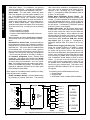
Up to 4 GEM-ACM1D modules may be connected to a
GEM-X255 control panel via standard, unshielded station
wire. Each module is capable of controlling access
through 2 doors and uses a keypad location in the system
for communication. Any polling failures, AC/DC Power or
Battery Troubles associated with the ACM will be displayed as a KEYPAD/ACM TROUBLE at the other keypads.
Any ACM tampers will be displayed as a KEYPAD/ACM
TAMPER at the other keypads. GEM-X255 panel code version 5 or higher must be used for GEM-ACM1D module
installations.
Although the GEM-ACM1D performs all access decisions
immediately without consulting the panel, the panel limits
the number of users to 195. In addition, the Event Scheduler (requires use of PCD-Windows) is used to control user
access by scheduling "User Off" and "User On" events,
with the total number of events is limited by the panel to
255. Note: Be aware that more than one event can be
assigned to each user, and the total number of events allowed is always limited to 255 regardless of how many users are programmed.
The GEM-ACM1D requires the panel for uploading user
codes/attributes (and their associated schedules), uploading door attributes, digital dialer reporting and all Keypad/
ACM trouble/information displays.
Each of the two model 6005B access card readers can be
programmed to function independently on different doors,
or together controlling access for both sides of one door.
The GEM-ACM1D supports a variety of card readers, including the Polaris XYZ magnetic card reader, the ShadowProx proximity card reader, the HID proximity readers,
and the 26-bit standard Wiegand card readers. The GEMACM1D also supports the use of any "Request to Exit" device, including the T-Rex exit detector.
* UL installations require JP3 to be removed.
** Not Evaluated by UL.
*** Requires GEM-2D to be installed.
SPECIFICATIONS
Housing Dimensions: 11"x121/8"x3" (28x30.8x7.6cm)
HxWxD
GEM-X255 Current Draw: 5mA
Operating Temperature: 0–49°C (32-120°F)
Input Power: 16.5VAC via CLASS 2 Plug-In 50VA Transformer
Door Zone Loop Voltage: 10-13VDC
Door Zone Loop Current: 2.4mA with 2.2K EOLR
Door Zone Loop Resistance: 300 ohms maximum
Combined Door Lock Power: D1 PWR (terminals 3+ and
4-) + D2 PWR (terminals 5+ and 6-)
Voltage Rating: 12VDC
Maximum Current: 1.5A
Battery Standby Time:
1. JP3 not installed: Standby Time = 0*
2. JP3 installed (factory default): Refer to battery
standby chart on page 8**
Reader 1 PWR: READER 1 PWR (terminals 17+ and 18-)
Voltage Rating: 12.5VDC to 11.7VDC with JP1 set to
12V (default). 5V with JP1 set to 5V.
Maximum Current: 125mA
Battery Standby Time:
1. JP3 not installed and 4AH battery used = 4 Hour*
2. JP3 installed (factory default): Refer to battery
standby chart on page 8**
Reader 2 PWR***: READER 2 PWR (terminals 35+ and 36-)
Voltage Rating: 12.5VDC to 11.7VDC with JP4 set to
12V. 5V with JP4 set to 5V.
Maximum Current: 125mA
Battery Standby Time:
1. JP3 not installed and 4AH battery used = 4 Hour*
2. JP3 installed (factory default): Refer to battery
standby Chart on page 8**
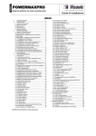
TABLE OF CONTENTS
GENERAL DESCRIPTION .................................................................... 1
SPECIFICATIONS ............................................................................... 1
LIST OF ACCESSORIES ...................................................................... 2
SYSTEM REQUIREMENTS .................................................................. 2
PLAN YOUR INSTALLATION ............................................................... 2
INSTALLATION/MOUNTING INSTRUCTIONS ..................................... 3
WIRING/CONFIGURATION ................................................................. 3
SECOND DOOR INSTALLATIONS ....................................................... 6
STANDBY-BATTERY CALCULATION WORKSHEET .......................... 8
PROGRAMMING THE ACM1D ............................................................. 9
ACM SYSTEM TROUBLES .................................................................. 14
DIRECT ACCESS PROGRAMMING .................................................... 15
ACCESS CONTROL USER'S CHART .................................................. 19
EVENTS LOG AND KEYPAD DISPLAY EXAMPLES ........................... 20
WIRING DIAGRAM ............................................................................... 23
WARRANTY .......................................................................................... 24
1
GEM-ACM1D Power Supply
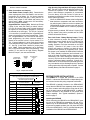
The GEM-ACM1D has an integral power supply which includes two primary linear regulators. The first regulator is
used to power the panel, the card readers and to re-charge
the battery. The panel and card readers are supported
with battery standby. The second regulator is used to supply up to 1.5A 12VDC for the door locks, which provides
enough current to support two 750mA magnetic locks.
The Door Lock Power has an option to enable battery
standby with a shunt connector placed across jumper JP3
(factory default). The battery is prevented from damage
caused during extended power failures with a battery drop
out circuit that disconnects the battery when there is no AC
present and battery voltage drops to approximately 9VDC.
When AC is restored, the battery is automatically reconnected and begins to recharge.
The GEM-ACM1D tests the battery under load every 4
hours and when the RESET button is pressed. The low
battery condition will only restore after it passes the active
test. The duration of this test is 15 seconds.
There are several advantages to this power supply design.
The separation of the door lock power from the rest of the
system reduces the likelihood that turning off the power to
the door lock coils will affect performance of the system.
The use of linear versus switching regulators significantly
reduces electrical noise that may hinder the sensitivity of
proximity card readers.
LIST OF ACCESSORIES
HID Prox Point Plus Model 6005B
Any UL 294 Listed door lock
Proximity cards: Two card formats are supported:
(1) NAPCO standard 36 bit format or
(2) HID standard 26 bit format.
SYSTEM REQUIREMENTS
The following system hardware is required:
Gemini GEM-X255 Control Panel version 5 or higher.
EPROM Upgrade must be installed in control panel.
PLAN YOUR INSTALLATION
Before installing your GEM-ACM1D access control accessory, give careful consideration to the design and physical
layout of the system. Access control points, keypad
zones, ACM zones and all other system components
should be planned in advance to ensure an efficient and
complete installation. It is recommended that you perform
all installation steps in the same sequence as is listed in
this manual.
After selecting all access locations, be sure to then locate
the GEM-ACM1D as closely as possible to the selected
access control doors, easily accessible for servicing, and
within 1000 feet of the GEM-X255 control panel. Standard
§
†
2
A GEM-PRINT is required on the system to print.
A second GEM-ACM1D could also be used.
22-24 gauge wire is recommended for all connections between the panel and the GEM-ACM1D, and 18 gauge wire
for all door strikes. Avoid running wires parallel to other
types of wiring that can cause electrical interference.
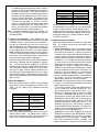
Typical Installations
There are two basic ways the GEM-ACM1D may be installed to provide access control, both are described below:
Option 1 uses a single card reader on the exterior of the
restricted area and a "Request to Exit" button within the
restricted area. This method only requires a single card
reader for each access door. This method is limited in
that only entrance via the card reader is logged or
printed§. The use of the "Request to Exit" button is not
logged (anyone can exit).
Option 2 uses 2 card readers (one reader mounted inside and another outside the restricted area); both connected in parallel to a single card reader interface. This
method requires presenting the credential for both entry
and exit from the restricted area. Although each presentation of the credential is logged and printed†, whether
the presentation was used to enter or exit the restricted
area cannot be determined.
Integrating the Fire Alarm System
Before installing the access control system, be sure to consult with the authority having jurisdiction to be sure to comply with all local codes. NFPA requires that the Fire Alarm
System has some control over the access doors. In the
event of a Fire Alarm or the loss of primary power (typically
AC), all access doors must be unlocked.
The "Emergency Free Access" zone is designed for this
integration. The output(s) from the fire alarm system must
be wired so that if there is a fire alarm or AC failure of the
fire alarm system, the "Emergency Free Access Zone" is
either shorted or opened. See page 3 for recommended
programming and wiring information.
Keypad Placement
A keypad should be located near any access door that can
be used to arm the system, so that the status of all the
zones up to the door can be determined (UL grade A requirement).
Additional Accessory Requirements
Up to three GEM-X255 zones may be dedicated to each
Access door. These three zones are the (1) Door, (2)
Forced Entry Zone and (3) Door Ajar Zone. If used, each
of these zones (up to 24 on a full system) will require either
1 of the 8 panel hardwire zones, a GEM-EZM8 zone or a
Wireless zone. If the zone is not 1 of the 8 panel zones,
then either (a) the zone will require the correctly addressed
GEM-EZM8 to be physically wired to the system, or (b) a
wireless receiver (GEM-RECVX 8/16/96/255) must be
physically wired to the system.
INSTALLATION/MOUNTING INSTRUCTIONS
After the mounting location and all access control doors
are selected, install the GEM-ACM1D as follows:
1. Install the GEM-ACM1D. The GEM-ACM1D housing
is designed for vertical surface mounting indoors in a
dry, secure location. When selecting a mounting location, ensure that the housing is accessible when future
servicing is required. Back-up battery must be located
within the secure housing. Mount the housing using the
two middle mounting holes and at least one bottom
mounting hole. Important Note: The GEM-ACM1D is
powered by a linear power supply which is the preferred
power supply for card proximity readers due to their
very low electrical noise (compared with switching
power supplies). However, be aware that linear power
supplies do generate moderate heat. Therefore mount
the GEM-ACM1D in a location that provides air circulation around the unit, particularly directly above the
housing. Do not install the GEM-ACM1D in confined
locations. Note: For UL installations, the GEMACM1D must be mounted within a protected premises.
2. Install Accessories. Mount all devices for each controlled access door:
a. Mount all required keypads.
b. Mount access card readers.
c. Connect door strikes (mag locks). Recommended
door strikes are "Fail Safe" locks which open when
power fails. Note: Local jurisdictions may prohibit
"Fail Secure" locks (which remain locked when
power fails) for fire escape routes.
d. Door contacts must be hardwired directly to the
GEM-ACM1D. Do not use wireless contacts.
e. Optional accessories such as an egress button, audible silence button, etc. should be mounted inside
the restricted area.
INSTALLATION/MOUNTING INSTRUCTIONS
Access Groups
Useful when designing an access control system, an Access Group is a collection of users who all have similar attributes; they all enter and exit the same access door, and
all keep to the same basic schedule when using the system. To keep the system organized and easier to manage, these users can be given a group name and assigned
to a specific range of contiguous user numbers (total range
is 1-195). Thus when deactivating and activating cards is
required, errors as to scheduling and other attributes can
be minimized. For new installations, we recommend that
installers program several users into the system (all with
similar attributes) to help reinforce the concept of Access
Groups for future programming.
3. Install Tamper Switches. J1 must be cut to enable
tamper. Normally open tamper switches (not supplied)
can be installed in the front and back of the cabinet to
provide protection from unauthorized entry. The tamper
switches are normally open switches used in a normally
closed tamper circuit. The front tamper switch protects
the cabinet door and the back switch protects against
removal from the wall. The normally open tamper
switches are connected in series between terminal 11
(positive +12V) and terminal 12 (ground). Note: UL
requires that the unit is mounted inside the protected
premises and therefore does not require tamper
switches to be installed.
4. Remote AC On Indicator. Dedicate a zone to each
GEM-ACM1D in the system with the following features:
• “Never Arm”
• Do not program “Burg Output”, “PulseBurg Output” or
“Fire Output”
• Program the zone for the area of the GEM-ACM1D
and GEM-2D (if used).
• Program the zone description “GEM-ACM1D X AC
FAIL” where X= the number of the GEM-ACM1D.
5. Other Connections. Wire earth ground to terminal 13
using a No. 16 AWG. or larger wire to a metal coldwater pipe. Do not use a gas pipe, plastic pipe or AC
ground connections. NOTE: Grounding connections
should avoid bends in the grounding wire whenever
possible.
6. Connect Transformer. Install a 16.5VAC/40VA transformer to provide power to the GEM-ACM1D. Connect
the red battery lead (E200) to the positive battery terminal and the black battery lead (E201) to the negative
battery terminal. Do not apply power until all wiring/
connections are complete.
Table #1: Card Reader Connections
GEM-ACM1D Terminal Number
GEM-ACM1D Terminal Description
17 (+)
Reader Power
HID Prox Point Plus Model 6005B Wires
Red (+ DC)
18 (-)
Reader Power
Black (- Ground) & (Shielded Ground)
19
Reader Data 1
White (Data 1)
20
Reader Data 0
Green (Data 0)
21 (-)
Red LED
Brown (Red LED)
22 (-)
Red & Green LED
Orange (Green LED)
23 (-)
Reader Sounder
Yellow (Beeper)
(Not Used)
(Not Used)
Blue (Hold)
(Not Used)
(Not Used)
Violet (Card Present)
* Tamper Connection not available on HID 6005B
**Polaris Only
Be sure to place jumper JP1 in correct configuration for 5 volt of 12 volt reader operation. See "Card Reader Power Jumper" further in this manual for
proper power configuration.
3
INSTALLATION/MOUNTING INSTRUCTIONS
FOR UL INSTALLATIONS
The following is required in UL installations:
1. The GEM-X255 must be installed and programmed as
required for the application.
2. A keypad must be located next to any access door, to
provide an indication (at the time of arming the system)
that all protection up to the egress door is set for duty
and the status of the GEM-ACM1D primary power.
3. Follow procedure on page 3, INSTALLATION/
MOUNTING INSTRUCTIONS, Step 4, "Remote AC
On Indicator".
4. Install front and back tamper switches as described in
the Installation Instructions provided (WI1278).
5. Use Prox Point Plus Model 6005B as card reader.
6. Use only UL Listed door locks.
7. Remove shunt connector from JP3 (remove battery
standby from D1 PWR and D2 PWR) assuring minimum 4 hour battery standby of GEM-ACM1D burglar
accessory functions.
8. Follow wiring notes on GEM-ACM1D Wiring Diagram.
WIRING/CONFIGURATION
All inputs and outputs, door strikes, card readers and all
other accessories should first be installed as detailed
above. Also, place all correct shunt connectors on jumpers. Note: Do not apply power until all wiring is complete.
Both AC and battery connections must be made before the
GEM-ACM1D will function properly. Always connect the
AC power before connecting the battery to avoid system
troubles.
Refer to the wiring diagram on page 23.
1. Connect to the Remote Bus. GEM-ACM1D Terminals 7-10 provide the control panel interface. Connect
as per the table below:
Table #2: Remote Bus Connections
GEM-X255 Terminals
GEM-ACM1D Terminals
9 (+)
7 (+)
10 (-)
8 (-)
11 (TX-Green)
9 (RX-GRN)
12 (RX-Yellow)
10 (TX-YEL)
Clamping
Diode
(supplied)*
Magnetic Lock
3
(+) D1 PWR
4
(–) D1 PWR
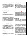
2. Connect Electric Door Locks.
NOTE: Before installation, always check with local
laws having jurisdiction concerning the installation of
magnetic locking devices. There may be strict limitations with regard the installation of magnetic or similar
exit door locking devices. Local laws may require the
installation of electrically separate panic hardware to
ensure the door can be opened in the event of an
emergency.
Door lock outputs are controlled by schedules programmed into the panel. These door lock outputs can
operate DC-powered locking devices such as magnetic
door locks or other electromechanical locks and can be
configured to operate in "Fail Secure" (which remain
locked when power fails) or "Fail Safe" (which unlock
when power fails) configurations.
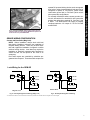
For normally de-energized door locks, connect ground
to terminal 4, wire terminal 3 to terminal 14, then connect the positive door strike wire to terminal 16. See
wiring diagrams (Figs 1 and 2 below) for both normally
energized and de-energized door locks. The GEMACM1D can supply a constant combined maximum
12V output of 1.5A for D1-PWR and D2-PWR.
3. Connect Door Contacts. Supervised normally closed
door contacts can be wired in series with a 2.2K end-ofline resistor between terminals 25 and 26 (place the
supervisory resistor in series at the door contact).
4. Additional Accessories. Optional devices such as a
Request to Exit button, an audible silence button, and a
Request to Arm button are described below.
• A Request to Exit button is mounted inside the secured area and is used to unlock the entry door without requiring a second card reader. The RTE button
is a normally open momentary switch wired between
terminals 27 and 28.
• An Audible Silence button is mounted inside the
secured area and is used to silence the card reader
sounder during door ajar conditions, and kick-in conditions. The Audible Silence button is a momentary
normally open switch wired between terminals 24-25
(SND OFF).
• A Request to Arm button can be mounted inside
Clamping
Diode
(supplied)*
(+) D1 PWR
4
(–) D1 PWR
14
16
14
15
COM
N/C
COM
N/O
GEM-ACM1D
Fig. 1: Normally Energized Lock Wiring ("Mag Lock")
Electric Strike
GEM-ACM1D
Fig. 2: Normally De-Energized Lock Wiring
* The diodes shown above are used to reduce the electrical noise produced when internals coils of the magnetic lock are de-energized.
4
3
5. Connect Card Reader(s). Each GEM-ACM1D can
control one access card reader and two when used with
a GEM-2D module. Card readers can be installed on
one door (to control both entry and exit) or when used
with the GEM-2D on two separate doors (to control access in one direction only). Connect the Card Readers
to the GEM-ACM1D as shown in the table below.
Note: Connecting the power lead of a 5VDC reader to
a 12VDC configured power terminal may damage the
card reader. See "Card Reader Power Jumper" further
in this manual for proper power configuration.
Each ACM will operate with any card reader that transmits data in a Weigand format, regardless of manufacturer. Two card formats are supported: (1) NAPCO
standard 36 bit format or (2) HID standard 26 bit format.
The "embossed" number printed on the face of the
card, up to 6 digits, must be manually entered as the
user code (see Programming pages 12 and 18). When
this embossed number is entered and configured in the
system, the number cannot be entered at a system keypad for access.
Reader LED Indications
Many card readers include an LED for visual feedback
when access cards are presented to the reader. See
Table 3 for the variety of LED indications and their
meanings.
Table 3: Reader LED Indications
LED INDICATION
ACCESS CONDITION
Steady Red
Door Locked
Short Steady Green
Card Read--Invalid card or
disabled user
Long Steady Green
Card Read--Valid card, user
enabled (door unlocked)
Alternating Green and Red
(Downloading PCD-Windows
Program to ACM)
Remote Status LED's (Optional)
Some card readers provide LED's that can be wired to
indicate system status. For readers with a snap-on
bezel and red and green LED's, wire to terminals 30
and 31 (door 1) and terminals 48 and 49 (door 2).
INSTALLATION/MOUNTING INSTRUCTIONS
or outside the secured area and is used in conjunction with a proximity card (enabled for arming) presented at a card reader. When the RTA button is
pressed, a window of time is created during which a
valid card must be presented to the card reader in
order for arming to take place. This window of time
is equal to six times (6x) the time programmed in the
"Un-Lock" time (see pages 11 and 16) The RTA
button is a normally open momentary switch wired
between terminals 28 and 29. Before arming, the
area to be armed must be secured (all protected
doors closed, all motion sensors stable, etc.).
Note: Consult all installation instructions provided with
each accessory before installation and connection to
the GEM-ACM1D.
Table 3a: Remote Status LED's
LED INDICATION
SYSTEM CONDITION
Steady Red
System Armed
Red LED is off
System Disarmed
Blinking Red
System in Alarm
Steady Green
System Ready to Arm
Green LED is off
System Not Ready to Arm
When Stealth Mode is enabled, the LED indications
are displayed for one minute only. See Stealth Mode
section on page 10 below. When Stealth Mode is
disabled ("normal operation"), the LED's are always
enabled and mimic the Keypad Status LEDs for the
following functions only: Armed, Disarmed, Ready,
Not-Ready and Alarm.
Card Reader Sounder Operation
Many card readers include a sounder for audible feedback. The sounder output can be connected to local
warning devices for:
• Access Door Kick-In. Kick-In occurs when a locked
access door is opened (the n/c circuit between terminals 25-26 or 43-44 opens). A "Kick-In" can also occur if either door circuit is shorted while locked (a supervisory resistor should be connected as close to
the door contact as possible, as required for Grade A
installations). The Sounder Out terminals 23 and/or
41 turns active low, and the local sounder activates
and remains active until the access door is closed.
Additionally the "Kick-In" condition will cause the
GEM-X255 connected to the GEM-ACM1D to sense
the zone programmed "Kick-In Zone" as faulted. Depending on the panel program, a faulted "Kick-In
Zone" will generate an alarm or trouble. Typically,
this zone would be programmed for 24-hour and Burglary output. The panel will continue to sense this
zone as open until the door contact is restored.
• Door Ajar. The access door is open for 30 seconds
or longer. The local sounder activates and remains
active until the door is closed.
A "Door Ajar" condition causes the GEM-ACM1D to
turn the (-) SND OUT (terminal 23) active low. Typically, this activates the card reader sounder. A remote low current sounder may be wired to the SND
OUT and (+) READER PWR (terminal 17), but be
aware that the sounder will activate whenever the
GEM-ACM1D uses the SND OUT terminal to generate sounds on the card reader (valid card, RTE button press, first swipe of double swipe arm, etc.). The
SND OUT will remain on until the door is closed or
until the SND OFF button is pressed. (The SND OFF
button is a N/O momentary push button wired to terminals 24 and 25 of the GEM-ACM1D).
Additionally the "Door Ajar" condition will cause the
GEM-X255 connected to the GEM-ACM1D to sense
the zone programmed "Door Ajar Zone" as faulted.
Depending on the panel program, a faulted "Door
Ajar Zone" will generate an alarm or trouble. The
panel will continue to sense this zone as open until
5
the door contact is restored.
SECOND DOOR INSTALLATIONS
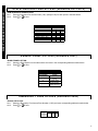
6. Other Connections and Jumpers
Card Reader Power Jumper (JP1). Determine the
power requirements of the card reader in use and connect jumper JP1 as follows: If a 12V device, place the
jumper on the top two pins (pins 1 and 2) and if a 5V
device, place jumper on the middle and bottom pins
(pins 2 and 3). Note: Jumper set to 12V from factory.
See wiring diagram for details.
Keypad Address Jumper (JP2). Notice that JP2 has
5 pairs of pins, each pair forming a vertical "column".
For JP2, the Access reader uses a keypad location in
the system for communication (Keypad #1 must NOT
be selected as an ACM type). The JP2 pin "columns"
1-4 must reflect (in hexadecimal) the keypad/ACM address to be selected in the panel programming. Therefore, if keypad address 2 is to be used for the ACM in
panel programming, the shunt connector should be
placed on the second "column" of pins marked "2" in
JP2. If keypad address 3 is to be used, place jumpers
on the first and second "column" of pins marked "1" and
"2". See Fig. 3 and Table 4 below for jumper placement. Note: Panel programming is to be performed
later, in the section below "Panel Programming". Pins
marked "5" are used for the high security "Degrade
Mode Off Jumper", see next section below.
Card Reader
Power Jumper
(5)
(1-4)
1 2 3
12V
High Security
Jumper
Keypad
Jumper
4 5
5V
JP1
JP2
High Security--Degrade Mode Off Jumper (JP2 Pins
#5). This pair of pins on the far right (5th "column") determines the operation of the GEM-ACM1D module
when a bad checksum computation is encountered.
From the factory, JP2's fifth "column" of pins are unpopulated, and therefore provides a lower security level
for the system as follows:
• When the GEM-ACM1D detects a bad configuration
data checksum computation and loses communication with the panel (unable to receive an update), the
GEM-ACM1D will grant access to any user who has
a SIA 26-bit Standard card or a NAPCO proprietary
36-bit card.
If higher security is desired, fifth "column" of pins in JP2
can be shorted using shunt provided and the GEMACM1D will not allow access.
Door Lock Power - Battery Backup Jumper. Placing
a shunt connector on jumper JP3 (factory default) enables battery power backup for the D1 PWR and D2
PWR outputs. Jumper JP3 will not affect the battery
standby operation of all other terminals on the GEMACM1D. Therefore if AC power is lost, the GEMACM1D will continue to function, but doors will not be
powered unless powered by a separate circuit. When
this jumper is not installed, the GEM-ACM1D fulfills the
UL 4 Hour Standby requirement (and is allowed to remain a UL listed mercantile burglary accessory to the
GEM-X255) even when drawing the maximum rated
current (1.5A) from the door locking mechanism power,
with the 4 amp-hour battery connected. If jumper is installed and AC is lost, doors will be powered by the battery, but batteries may be discharged quickly if the door
locking mechanism requires power to operate. See the
Standby Battery Calculation Worksheet on page 8.
Fig. 3: Jumpers JP1 and JP2
Table 4 Keypad Jumper JP2 Configuration
JP2: Pins "columns" 1 through 5 are depicted from
left to right using the illustrations in the table below:
Unconnected jumpers are white:
Shorted Jumpers are black:
Keypad
Address
1
6
JP2 Jumper Pin
"Column" Shorted
JP2
Illustration
Not used, must be a keypad.
Do not configure ACM for Keypad #1
2
2
3
1 and 2
4
3
5
1 and 3
6
2 and 3
7
1 and 2 and 3
8
4
9
1 and 4
10
2 and 4
11
1 and 2 and 4
12
3 and 4
13
1 and 3 and 4
14
2 and 3 and 4
15
1 and 2 and 3 and 4
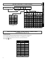
SECOND DOOR INSTALLATIONS
The GEM-2D is a module that connects to the GEMACM1D. It allows the GEM-ACM1D to independently control a second access relay using a separate card reader.
The GEM-2D is basically identical to the GEM-ACM1D,
except that the GEM-2D uses separately wired card readers, door contacts and locking device relays that all function in the same manner as the GEM-ACM1D. In addition,
readers connected to the GEM-2D do not provide Arm/
Disarm capability. See "Typical Installations", Options 1
and 2 on page 2.
Installing the GEM-2D
When connecting the GEM-2D to the GEM-ACM1D, insert
the pins of the GEM-2D into receptacles J4F and J5F located on top of the GEM-ACM1D. Before inserting, align
all pins and receptacle sockets, then fully insert the GEM2D into the GEM-ACM1D. See Fig. 4 below illustrating the
installation of the GEM-2D into the GEM-ACM1D.
SECOND DOOR INSTALLATIONS
operate DC-powered locking devices such as magnetic
door locks or other electromechanical locks and can be
configured to operate in "Fail Secure" (which remain
locked when power fails) or "Fail Safe" (which unlock
when power fails) configurations.
For normally closed door strikes, connect ground to terminal 6, wire terminal 5 to terminal 32, then connect the
positive door strike wire to terminal 34. See Figs. 5 and
6 below. The GEM-ACM1D can supply a constant
combined maximum 12V output of 1.5A for D1-PWR
and D2-PWR.
Fig. 4: Installing the GEM-2D. Before inserting, align all pins and
receptacle sockets, then fully insert the GEM-2D into receptacles J4F
and J5F located on top of the GEM-ACM1D.
GEM-2D WIRING/CONFIGURATION
Connect 2nd Door Strike (Mag Lock).
NOTE: Before installation, always check with local
laws having jurisdiction concerning the installation of
magnetic locking devices. There may be strict limitations with regard the installation of magnetic or similar
exit door locking devices. Local laws may require the
installation of electrically separate panic hardware to
ensure the door can be opened in the event of an
emergency.
Door strike outputs are controlled by schedules programmed into the panel. These door strike outputs can
Lock Wiring for the GEM-2D
Clamping
Diode
(supplied)*
Magnetic Lock
5
(+) D2 PWR
6
(–) D2 PWR
Clamping
Diode
(supplied)*
5
(+) D2 PWR
6
(–) D2 PWR
32
34
32
33
COM
N/C
COM
N/O
GEM-2D
Fig. 5: Normally Energized Lock Wiring ("Mag Lock")
Electric Strike
GEM-2D
Fig. 6: Normally De-Energized Lock Wiring
* The diodes shown above are used to reduce the electrical noise produced when internals coils of the magnetic lock are de-energized.
7
STANDBY-BATTERY CALCULATION WORKSHEET
Use the procedure given below to determine the required standby battery capacity in Ampere-Hours (AH). NOTE: It is not totally
accurate to merely divide the combined standby current (in amperes) by the battery amp-hour rating to obtain the standby time (in
hours), since other factors (control-panel charging capabilities, temperature, battery condition, battery discharge rate, etc.) affect
battery operation. The following calculations will yield the theoretical standby time of the 4AH and 7AH batteries at room temperature. NOTE: JP3 is used to provide standby power to D1 and D2 power output terminals. When AC power is removed, these terminals will not have battery standby voltage available. UL has only evaluated the system with JP3 removed. In addition, this
Standby-Battery Chart has not been evaluated by UL.
1. STANDBY CURRENT
STANDBY CURRENT (Amps)
DEVICE
QTY
EACH
GEM-ACM1D
1
X
GEM-2D
1
X
=
Reader 1 of 2
X
=
Reader 2 of 2
X
=
Door Strike 1*
X
=
Door Strike 2*
X
=
X
=
X
=
X
=
0.04
TOTAL
=
TOTAL STANDBY CURRENT
0.04
Amps
*Not applicable if JP3 is not installed. JP3 must NOT be installed in UL installations.
7AH Battery Standby Time @ 20 degrees C
Current
Capacity (AH)
Standby Time
0.35A
7.0 AH
20 Hours
0.70A
6.3 AH
9 Hours
1.4A
5.6 AH
4 Hours
1.8A
5.13 AH
2.85 Hours*
4AH Battery Standby Time @ 20 degrees C
8
Current
Capacity (AH)
Standby Time
0.2A
4.0 AH
20 Hours
0.40A
3.6 AH
9 Hours
0.80A
3.2 AH
4 Hours
1.40A
2.8 AH
2 Hours
1.8A
2.61AH
1.45 Hours*
PROGRAMMING THE GEM-ACM1D
Note: The panel must not be programmed with an unattended remote download. The system must always be
tested after programming or re-programming.
PCD Windows Screens
Several PCD-Windows screens* are used. After PCDWindows is installed and running, create a new GEM-X255
account.
Note: A door contact on an ACM takes over for an existing Physical Zone. To add additional zones to a panel,
use an EZM or an RF Wireless Receiver. Map the ACM
door, Forced Door and Door Ajar to these zones.
1. Enable ACM Access
In PCD-Windows, click the System Assignment button, and select the System Options tab. In the System
area at the right, check "Enable ACM Access" and click
OK to save. This step should be performed first because it makes PCD-Windows* display the correct
screens for access control.
This can also be performed in Direct Address Program
Mode: Go to address 2423 and enable bit zero (press
1 on the keypad) to allow the GEM-ACM1D and GEM2D accessories to function in the system.
2. ACM/Keypad Assignment
Click the Keypad Assignment button, and select the
ACM Assignment tab. This screen allows you to associate the hardware (installed ACM modules) to areas,
mapped zones, external relays, and other elements of
the security system. An EZM or a GEM-RECV must be
assigned to the zones programmed for each door. Up
to 4 ACMs (each with 2 doors with 3 zones each) for a
total of 24 out of a possible 255 zones in the panel can
be programmed for access control. Configure the access control modules by entering or selecting the information in the areas provided:
ACM: Up to four GEM-ACM1D modules can be used
in a system.
Keypad: Assign the physically installed ACM to a keypad location in the system. Keypad number 1 cannot
be used, therefore select a keypad location 2-15.
Door: Two doors are allowed for each GEM-ACM1D
module, when a GEM-D2 module is installed. The
Door column simply displays these two doors to allow
for further programming below.
Area: Assign an area to each ACM door. If the access
* For local programming or downloading only.
PROGRAMMING
After all wiring and connections have been made (refer to
all previous steps, above), first program the GEM-X255 via
the PCD-Windows Quickloader* download software (use
version 4.5 or later). The GEM-X255 will then transfer the
access programming to the GEM-ACM1D. Direct Address
Program Mode can also be used for programming via the
keypad, with the exception of schedules. To schedule the
ACM users, PCD-Windows MUST be used. See WI1035
for PCD-Windows installation and configuration instructions.
area is shared by both the GEM-ACM1D and GEM-D2,
then the same area is used for each door. For each
door programmed, there are three possible events that
can occur and thus activate the zone specified. You
MUST designate a separate zone number for each of
the three possible events below.
• Zone: Assign a zone number to activate when the
access door is opened. (wired to door contacts).
• Forced Entry Zone: Assign a zone number to activate when a door is opened, but not unlocked.
• Door Ajar Zone: Assign a zone number to activate
when the door is opened, but not closed, for a specified period of time.
Note: These zones can be programmed into the
control panel (via the keypad) using Direct Address
Program Mode: Addresses 2740 -2779 correspond
to the 4 possible ACM's and their zones. The Area
# for Door 1 is controlled by the existing Keypad
Programming table (Address 2425 to 2439). The
assigned area for Door #2 for each ACM must be
entered in addresses 2748, 2758, 2768 and 2778
and must not be left blank if Door 2 is to be used.
See the Direct Address Programming Instructions
on page 15 for more details.
Arm All Areas Allowed: Check to allow multiple arming of areas. However, in order for this feature to function, several other programming conditions must also
be in effect: (1) The proximity card used must be programmed to allow for arming. (2) The card must be
programmed to allow for arming multiple areas as
specified in the User Assignment screen, "ACM Area"
column (up to 8 areas).
Uncheck to restrict users to arming only those areas in
which the card reader physically resides (and for which
the card reader is programmed), and only among those
areas specified in the User Assignment screen, "ACM
Area" column.
For example, if a user is permitted to arm areas 1-5 (as
specified by the User Assignment screen "ACM Area"
column), and this feature is checked, that user will be
permitted to arm areas 1-5 at any specified reader. If
unchecked, then the user will be permitted to arm only
the area in which the card reader resides--area 2 will
arm if using an area 2 reader, or area 3 will arm if using
an area 3 reader, and so on.
Corresponds to GEM-X255 Direct Address Program
mode addresses 2784-2791.
See also step 5,
"Configure Areas" on page 12.
Disarm All Areas Allowed: Check to allow multiple
disarming of areas. However, in order for this feature to
function, several other programming conditions must
also be in effect: (1) The proximity card used must be
programmed to allow for disarming. (2) The card must
be programmed to allow for disarming multiple areas as
specified in the User Assignment screen, "ACM Area"
column (up to 8 areas).
Uncheck to restrict users to disarming only those areas
in which the card reader physically resides (and for
which the card reader is programmed), and only among
those areas specified in the User Assignment screen,
9
card used must be enabled for arming/disarming functions, and must be presented twice within the time
specified in the "Two-Swipe Arm Time" detailed on
page 11. Corresponds to GEM-X255 address 2780, bit
0 (press 1 on the keypad).
Enable Napco Proprietary Access Format: The
GEM-ACM1D or GEM-2D supports two proximity card
formats: (1) NAPCO standard 36 bit proprietary format
or (2) HID standard 26 bit format. Check to allow the
GEM-ACM1D or GEM-2D to recognize this standard 36
bit card format. Corresponds to GEM-X255 address
2780, bit 1 (press 2 on the keypad).
Enable Facility Code: Not all proximity cards contain
a facility code. If the cards used contain a facility code,
and you wish to allow the code to be used within the
system, check this feature. When enabled, the least
significant digit of the facility code must be used as the
most significant digit of the card access Code. See the
Code section within "Create an ACM User & Enter
User Codes" (item 3) on page 12. Corresponds to
GEM-X255 address 2780, bit 2 (press 3 on the keypad).
Enable Access Logging Into Burg Log: This feature
allows the viewable keypad log to display a limited
number of access control events. When unchecked,
the system will log access events in the access log,
which cannot be displayed at the keypad (limited to 800
events); when checked, access events will be logged
only in the burg log. Note: When configuring the event
logs, consideration should always be given to various
factors: (1) the size of the two event logs; (2) how
many events might be logged within a given time; (3)
the possible loss of event data due to excess events
causing the log to overwrite itself. This feature corresponds to GEM-X255 address 2780, bit 3 (press 4 on
the keypad).
PROGRAMMING
"ACM Area" column. For comparison, see previous
"Arm All Areas Allowed". Corresponds to GEM-X255
Direct Address Program mode addresses 2784-2791.
Stealth Mode: The card reader armed and status
LED's are designed to provide system feedback to users. If this feedback is not desired (such as for card
readers located outside the protected premises),
Stealth Mode can be enabled for each card reader assigned to active ACM areas. Check to enable and uncheck to disable Stealth Mode. When enabled, the
armed and ready status card reader LED’s are normally
off but are turned on for 1 minute by any of the following
events:
• Press a request to exit button
• Press a request to arm button
• Present a valid ARM/DISARM or ARM card to the
card reader
When the system is in alarm, Stealth Mode is disabled.
"Access Only" cards do not affect the status of Stealth
Mode.
Scheduled Free Access Index: An external relay can
be programmed to activate (via a schedule) to allow the
protected door to unlock and allow "free access" for the
scheduled time. This column links the enabled ACM's
to that external relay. If you wish to create a space of
time to allow free access through the access door (for
example 1 hour during lunch every day), first program a
1 hour lunch time schedule for the relay to activate (in
the Schedule Assignment screen, External Relay
Control tab). Then add the relay number to the Scheduled Free Access Index column for the ACM you wish
to control during that scheduled 1 hour time period.
Note: If an existing external relay exists on the system,
use the next available relay number. This selection corresponds to addresses 4072-4079 in the control panel
Direct Address Program Mode.
The following are new ACM related new events:
1. Access Granted
2. Access Denied
3. ACM Power Trouble, includes ACM Low Battery
Other aspects of the installed access modules are configured using this screen, including:
Enable Two-Swipe Arming: If checked, allows arming
by presenting a proximity card twice. The proximity
GEM-X255
AC Fail
N/C
ACM
1
COM
N/O
(+) 24 HR
Supervisory
Hardwired
(–) Zone
N/C
Fire
BUS
ACM
2
ACM
3
Door 1
RELEASE
Door 2
ALL
Door 3
Door 4
Door 5
Door 6
COM
2.2K EOLR
ACM
4
N/O
Fire Control Panel
Burg Control Panel
(Up to 4
ACM's)
Door 7
Door 8
(Up to 8
Doors)
Fig. 7: Integrate an Existing Fire Panel into the Access Control System
10
DOORS
DURING
FIRE
OR
AC POWER
LOSS
Example:
10/14/2003 04:50PM ACM2: Access Granted to User
4 : 903466 via Door 1
10/15/2003 05:35AM ACM1 Trouble: Power
10/15/2003 05:40AM ACM1 Trouble Restore: Power
These same 3 events viewed through a keypad appear as:
AccessGrnt 10/14 04:50PM A2D2U004
ACMPwrTrb 10/14 05:35AM ACM1
ACMPwrTrbR 10/14 05:40AM ACM1
Note: Characters in bold are built into panel default
program (English only) and Quickloader's language
download.
The following are ACM related events that are
mapped to the existing Keypad events
1. Panel/ACM# communication failure is logged using
the existing Panel/Keypad# communication failure.
2. ACM# Tamper is logged using Keypad# Tamper.
Text now reading "Keypad" will be changed to "KP/
ACM".
Enable Printing Access Events: If you have GEMPrint and compatible printers with the correct versions,
the Access Event log can be printed as they occur.
Corresponds to GEM-X255 address 2780, bit 4 (press
5 on the keypad). The GEM-PRINT version 4 is required.
Enable card presentation beep and green LED
flash:
Controls the card reader sounder and LED's. Many
types of card readers can be used with the GEMACM1D, and each may behave differently depending
on its design. The recommended HID card reader is
the HID Prox Point Plus Model 6005B-00, and this
reader will operate with regard to this feature as follows:
• Disabled: Will beep and flash green when card is
read, door ajar sound is enabled.
• Enabled: Will beep twice and green LED will display twice when card is read, door ajar sound is
enabled.
This feature corresponds to GEM-X255 address 2780,
bit 5 (press 6 on the keypad).
Un-Lock Time: Specifies the amount of time the user
is given to open the door after the card credential is
verified. A full explanation is presented below. Panel
address 2783 is used, and the value entered is defined
in seconds. Note: When the system is programmed
for "Two-Swipe Arming", the first time a card
(programmed for arming) is swiped, the door unlocks
for the standard "Un-Lock Time". The second time the
card is swiped, the door access "Un-Lock Time" is extended to four (4) times this programmed "Un-Lock
Time" value. Default is 5 seconds.
When a card credential is presented to the card
reader and is verified by the GEM-ACM1D to be a
valid and enabled user, the GEM-ACM1D energizes
the D1 Relay (which either removes power or supplies power to the door lock) unlocking the lock. The
lock will remain unlocked for the programmed "UnLock Time". If the door is not opened (as sensed by
the door contact) by the end of the "Un-Lock Time",
the lock power is reapplied/removed, re-locking the
door until another programmed card credential is presented. If the door is opened during the "Un-Lock
Time", power is immediately reapplied/removed such
that as soon as the door is closed, the door is immediately locked. Once the door is closed, another programmed credential must be presented for it to reopen, even if "Un-lock Time" has not expired from
the initial presentation of the programmed credential.
Once the door is unlocked and opened, a 30 second
"Door Ajar" time begins. If the door is not closed after thirty seconds the GEM-ACM1D initiate a "Door
Ajar" condition. See page 9 for more information
about "Door Ajar".
Two-Swipe Arm Time: Allows arming by presenting a
proximity card twice within this time period (the card
used must be enabled for arming/disarming functions).
Panel address 2782 is used and the value entered is
multiplied by 100 milliseconds (1/10th of a second).
Default is 40 (40 x 1/10 = 4 seconds).
Emergency Free Access: Panel address 4080 is
used. NFPA requires that all doors must be unsecured
("unlocked") during a fire alarm and/or a primary power
(typically AC) failure. Using outputs of the fire alarm
panel and wiring them to the zone input, existing fire
alarm systems can be integrated into the access control
system. See below for programming and wiring information.
Programming the GEM-X255 Emergency Free Access Zone Features:
a. 24 Hour Zone. This will cause the GEM-ACM door
relay to energize on a short and on an open.
b. No Alarm output. The Fire alarm system is required
to generate a temporal alarm with all the sounding
appliances in synchronization. The additional supplementary alarm output of the panel may confuse
the people inside the protected premises.
c. Do not program "Report on Alarm". The GEM-X255
panel is not listed as a Mercantile Fire Alarm and
should not report fire alarm data to the central station. Additionally this panel may interfere with the
more specific fire panel alarm report depending on
the telephone wiring.
d. Program "Keypad Sounder on Alarm" to the mapped
Emergency Free Access zone to enable the keypad
to display the emergency condition.
e. Use the correct Zone Descriptions to properly inform
the user of the condition (i.e. "Access Door Release").
11
PROGRAMMING
and ACM AC Power Failure
4. ACM Power Trouble Restore
The General Format, as printed by GEM-PRINT is as
follows:
Date – Time – ACM# – Event – User # – UserCode – Door #
PROGRAMMING
The output(s) from the fire alarm system must be wired
so that if there is a fire alarm or AC failure of the fire
alarm system, the "Emergency Free Access Zone" is
either shorted or opened. See Figure 7 for recommended wiring.
Wiring the Fire Panel to the Emergency Free Access Zone:
a. Wire a 2.2K EOLR across the Common and N/O
terminals of the dry fire panel alarm relay.
b. Wire "Emergency Free Access" zone (-) to Common
of Fire panel dry AC ON relay.
c. Wire Fire panel AC ON relay N/C to Common of fire
panel alarm relay.
d. Wire Fire panel alarm relay N/O to "Emergency Free
Access" zone (+).
3. Create an ACM User & Enter User Codes
Click the User Assignment button, and select the User
Assignment tab. Configure a user (1-255) by entering
or selecting information in the areas provided:
Description: Enter a description of the user, such as
their name.
Code: Enter the code of the proximity card assigned to
that user. Enter all numbers embossed on the card itself, and if there is a Facility Code, use the least significant digit as the first number of the Code. For example,
if the embossed card number is 78799 and the Facility
Code is 12, enter 278799 in the Code column for the
user selected.
AL (Authority Level): Select an Access Level (assigned
to the proximity card) from the drop down list. 0=No
Access, 1=Disarmed Access, 2=Always Access. For
example, if you wish to give the user assigned to this
card the ability to enter the premises while armed (and
then disarm via a keypad inside the premises), select
level "2". This selection corresponds to address 0013
in Direct Address Program Mode where bits 01 and 1
are used (00= No Access, 01= Disarmed Access, 10=
Always).
Code Type: Determines the category assigned to the
code (and thus to the specific proximity card). The
types include "No Arming", "Arm/Disarm", "Arm Only".
This selection corresponds to address 0013 in Direct
Address Program Mode where bits 2 and 3 are used
(00= No Arming, 01= Arm/Disarm, 10= Arm Only).
User Options: The IO ("Initially Off") column indicates
whether the user is initially "On" or "Off". For example,
if a user is "Off", then this user will always be disabled
unless there is a "User On" schedule programmed to
enable him (see step 6 "Create an ACM Schedule" below).
The default state for each user is
"On" (unchecked). If a user has a "User On" event
schedule, that the state for the user be "Off" (checked).
The remaining options are not used for ACM Programming, and will be grayed-out when a valid ACM area is
selected in the "ACM Area" column.
Area: The Area column and the ACM Area column are
mutually exclusive--either can be used but not both with
12
one user (row). The Area column assigns the keypad
user code to an area. To assign the user to an ACM
Area, see ACM Area section (below). Click the dropdown box to display the areas, and click each area to
highlight and select.
ACM Area: Assign a user (and their assigned proximity card) to an ACM area. Click the drop-down box to
display the areas, and click each area to highlight and
select. See also step 2 ACM/Keypad Assignment
("Arm All Areas Allowed") and step 5 Configure Areas
(Area Assignment button).
4. Edit Zones (Zone Assignment)
In section 3 above, zones were selected to possess
certain properties. For example, you may have assigned zone 1 to activate when the access door is
opened (wired to door contacts). You may wish to edit
each assigned zone with respect to how the system is
intended to be used.
For example, if the system is designed to allow a user
to access an armed system, then enter a disarm code
at an interior keypad, you would need to program the
zone as an Entry/Exit zone. However, if the system is
designed to be disarmed before entry, you may wish to
program the zone as a Perimeter zone. To edit zones,
proceed as follows:
Click the Zone Assignment button and the list of programmed zones appears. Double-click the zone you
wish to edit and the Zone Edit window appears. Click
to select a Zone Label, or double-click the Zone Label
to edit (Edit Zone Label window). A Zone Description
can be added, and Reporting Codes can be configured.
When complete, click OK to save.
5. Configure Areas (Area Assignment)
As previously explained in step 2 (Keypad Assignment button, ACM Assignment tab), the Arm All Areas
Allowed attribute is associated with the User Assignment screen. In addition, Arm All Areas Allowed is
also associated with the Area Assignment screen. The
Area Assignment tabs describe how different areas
function with relation to each other. Press the Area Assignment button, and view the three tabs:
Area Description tab: Type in text descriptions of
areas and messages as required.
Area/Disarm tab: Select areas that when disarmed
will silence the corresponding outputs located in
the selected areas.
Area Priority tab: Not to be used with "Arm All Areas Allowed".
See also step 3 ACM Area on page 12.
6. Create an ACM Schedule
Note: PCD-Windows download software MUST be
used to program schedules*.
Note: When the GEM-ACM1D loses communication
with the control panel, the user access schedule will be
abandoned and any user that has been programmed in
the system will be granted access.
Users are controlled by assigning them to a schedule.
* For local programming or downloading only.
* For local programming or downloading only.
example, the user who works 9AM-5PM, Monday
through Friday, click in the Date column of the schedule
you are changing (the Date Schedules window opens).
Click Day of Week drop down box and click to highlight
the days you wish to include.
IMPORTANT: After adding, changing or removing a
scheduled event, you must restart the control panel to
ensure that all new or existing scheduled events will
occur properly and without delay. To restart the panel
locally: Remove jumper JP5 from the top two pins
("Normal") and place the jumper on the bottom two pins
("Config"); then replace the jumper on the top two pins.
To restart the panel remotely via PCD-Windows*:
Click the Status/Control button and click Restart
Panel. Note that the remote connection to the panel
will be lost.
7. Download to Control Panel
Before proceeding, save your work (File, Save Work).
Press the Panel Communication button. In the Select
Transfer Operation drop-down box, select Download
to Panel. Check User Program Area, Dealer Program Area and Description Area. Click OK to initiate
the data transfer to the control panel. In UL installations, you must disable remote downloading (no unattended downloading allowed) and after changing the
program, you must verify panel operation at the panel
site.
APPLYING POWER
Before applying power, it is recommended to first
download the panel program using PCD-Windows
Quickloader download software. See the section
"Programming the GEM-ACM1D" on page 9. Once the
program is downloaded, applying power to the system
will initiate communication from the control panel to the
GEM-ACM1D. When communication is complete,
cards can then be programmed, tested and distributed
to users.
After downloading the panel program, first apply power
to the control panel by first inserting the transformer into
a standard 120V household duplex receptacle, then
connect the flying battery leads. System troubles will
appear at the keypad (due to the lack of ACM power, a
keypad/ACM trouble will appear). The zones associated with the doors will be open, and press <RESET>
to silence/acknowledge the Keypad/ACM trouble.
Next, apply power to the GEM-ACM1D (and GEM-2D if
installed) by inserting the transformer into a standard
non-switched 120V duplex receptacle, securing the
transformer via the center duplex receptacle screw.
Connect the flying battery leads to battery. There are
three LEDs on the face of the GEM-ACM1D module
which will light as follows: When power is applied, the
green AC ON LED on the module will turn on (steady).
Within the first 30 seconds of applying power to the
GEM-ACM1D / GEM-2D modules, the red polling LED
will flash rapidly (indicating it is uploading the panel program). After a few seconds, this red polling LED will
13
PROGRAMMING
By default all users (i.e. their proximity cards) are active;
the schedules restrict user card access. For example, if
an employee works 9AM through 5PM, program the
schedule to turn off starting at 5PM for the next 16
hours (until 9AM the next day). This schedule can also
be programmed as follows: Set user to be "Initially
Off" (see step 3 "User Options" above), then schedule
to turn on at 9AM for the next 8 hours.
To create an access schedule, click the Schedule Assignment button and select the Schedule tab. For the
first user, enter as follows:
Description: Enter text in the Description column
(such as the name of the user).
Event: Enter a description of the event in the Event
column (such as "User off" to restrict access during a
period of time). The following is a partial list of events
for the GEM-X255 panel associated with access control:
• External Relay On (RB3000)
• User On (Enable)
• User Off (Disable)
Index: The Index column is used to associate an event
to another "object" configured elsewhere in the system.
In access control systems, the object typically is a specific user/access card number or a specific External Relay number.
Normal Time: Since users are always enabled unless
restricted, the Normal Time will reflect the (a) the time
the period of restriction begins and (b) the length of time
the period of restriction will remain in effect. For example, if you wish to allow a user access only between
their working hours of 9AM through 5PM, enter (a) the
time of day (in 24-hour military time) the period of restriction will begin (enter "17:00"), and (b) the length of
time, in hours, this period of restriction will remain in effect (enter 16 hours). Therefore the entry will be:
"17:00-16:00".
Holiday Time: Used to restrict a recurring block of
time. For example, if you wish to restrict access every
year during the "Thanksgiving" holiday (which always
occurs on the 4th Thursday of November), enter as follows: (a) Click the Holiday Dates tab; (b) Type in a description of the holiday and click in the Date column to
open the Holiday Scheduler window. In the Date field,
all that is needed is November, therefore enter "11/**/
***" (*=wildcard). In the Day-of-Week field, enter "Th",
and in the Week Number field, enter "4" to designate
the 4th week. Press OK to save the data and press
Apply to save the holiday. (c) Program a time span for
all scheduled holidays: Select the Schedule tab, click in
the Holiday Time column of the schedule you are
changing (the "Time Schedules" window opens). Click
to highlight a blank time schedule and click Edit. In the
Time Scheduler dialog, enter "0:01" in the Start Time
field to signify 12:01AM, and enter 24 in the Time
Length Field. Press OK three times to save all data.
Scheduled restricted time can overlap with other scheduled restricted time if needed.
Date: Enter the dates of the week you wish to include
with the previously programmed "Normal Time". For
PROGRAMMING
then blink once per second (indicating it is communicating with the panel). The third Low Battery LED should
be off unless it detects a low battery.
Confirm all connections are correctly wired, all system
troubles are cleared, and all zones are closed. Test all
aspects of the system including access (use a programmed proximity card), all wired accessories (such
as the Request to Exit (RTE) button), all keypads and
zones (such as door ajar, etc.).
GEM-ACM1D System Troubles
A keypad ACM System Trouble display will be followed by
one or more of the following error codes:
E11-NNN - KEYPAD/ACM TAMPER. GEM-ACM1D accessory cover opened or removed. NNN is keypad
number.
E10-NNN - KEYPAD/ACM TROUBLE. ACM no response
to poll, buss not communicating with panel. NNN is
keypad number. Zones mapped to the access doors
will indicate faulted.
E54-000 - LOW BATT NO/AC. Power failure for ACM #1.
Check power transformer. Check for blown fuse or circuit breaker; general power outage. Also may indicate
battery below 11 volts. If battery not recharged
within 24 hours, replace it.
E55-000 - LOW BATT NO/AC. Power failure for ACM #2.
Check power transformer. Check for blown fuse or circuit breaker; general power outage. Also may indicate
battery below 11 volts. If battery not recharged
within 24 hours, replace it.
E56-000 - LOW BATT NO/AC. Power failure for ACM #3.
Check power transformer. Check for blown fuse or circuit breaker; general power outage. Also may indicate
battery below 11 volts. If battery not recharged
within 24 hours, replace it.
E57-000 - LOW BATT NO/AC. Power failure for ACM #4.
Check power transformer. Check for blown fuse or circuit breaker; general power outage. Also may indicate
battery below 11 volts. If battery not recharged
within 24 hours, replace it.
14
DIRECT ADDRESS PROGRAMMING
Direct Address Programming allows you to go directly to the address locations (up to 4095) and change the data entries
manually in order to customize your control panel options. The data entry location accepts data in one of three formats: Binary, Decimal and Hexadecimal. For more information, see the GEM-X255 Programming Instructions (WI1092).
KEYPAD #1: For ease of programming, it is recommended that a GEM-K1CA (Version 8) be used as Keypad #1.
(Regardless of which keypad is selected, all new keypads are configured as Keypad #1 out of the box). The instructions below are depicted using the GEM-K1CA keypad.
ACCESSING DIRECT ADDRESS PROGRAM MODE
1.
Enter the panel's Dealer Security Code, then press R.
2.
Answer NO to all questions until “ACTIVATE PROGRAM Y/N” is displayed; then press YES. NOTE: If you pass “ACTIVATE PROGRAM”,
scroll backward using B.
3.
Press C to enter the Address Program Mode. Address "0000" will display.
4.
5.
Press the 4 digits of the address (listed below). The existing data will display and the cursor will advance to the data field.
Program the address as required.
6.
Press U to save.
7.
Enter another 4-digit address to continue programming or press C to exit and resume normal keypad operation.
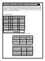
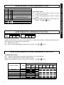
A C M Z O N E O P T I O N S ( AD D R E S S 2 7 4 0 - 2 7 7 9 )
ACM ZONE OPTIONS:
! Enter the Zone numbers (in decimal 1-255 format) for each option in the table below. Press U or D to save.
NOTE: Dark shaded data value box shows option not available. Note: The Area # for Door 1 is controlled by the existing Keypad Programming table (Address 2425 to 2439). The assigned area for Door #2 for each ACM must be entered in the table below (addresses 2748, 2758, 2768 and 2778) and must not be left blank if Door 2 is to be used.
ACM1 Zone Options
ADDR
Door Contact
Forced Entry Zone
Door Ajar Zone
Area # for Door 2
Reserved
Reserved
2740
2741
2742
ACM2 Zone Options
ADDR
Door Contact
Forced Entry Zone
Door Ajar Zone
Area # for Door 2
Reserved
Reserved
2760
2761
2762
Door 1
Door 2
2745
2746
2747
2748
2749
2743
2744
2763
2764
ADDR
Door 1
ADDR
2765
2766
2767
2768
2769
Door 2
ACM3 Zone Options
ADDR
Door Contact
Forced Entry Zone
Door Ajar Zone
Area # for Door 2
Reserved
Reserved
2750
2751
2752
ACM4 Zone Options
ADDR
Door Contact
Forced Entry Zone
Door Ajar Zone
Area # for Door 2
Reserved
Reserved
2770
2771
2772
Door 1
Door 2
2755
2756
2757
2758
2759
2753
2754
2773
2774
ADDR
Door 1
ADDR
Door 2
2775
2776
2777
2778
2779
15
A C M G L O B AL F L AG S ( AD D R E S S 2 7 8 0 )
ACM Global Flags
Option
ACM GLOBAL FLAGS:
OFF
1
Enable Two-Swipe Arming
OFF
2
Enable NAPCO Proprietary Access Format
OFF
3
Enable Facility Code
OFF
4
Enable Access Logging into Burg Log
OFF
5
Enable Printing of Access Events
OFF
6
Enable Card Presentation Beep and Green LED Flash
OFF
7
RESERVED
OFF
8
RESERVED
! 1.
Select the desired option entering the option
number (1-8) for each digit.
! 2. Enter corresponding option number in address
location.
NOTE: Dark shaded data value box shows option not
available. Press U or D to save.
A C M T I M E O U T S ( AD D R E S S 2 7 8 2 - 2 7 8 3 )
Maximum
Two-Swipe
Arm Time
(x100ms)
ADDRESS 2782
[Default = 030 = 3 seconds.]
Unlock Time
(sec.)
ADDRESS 2783
[Default = 5 sec.]
Address 2782 determines the maximum time allowed for the double swipe (x100ms). Address 2783 determines the
door unlock time, in seconds, after a successful entry.
! 1. Select timeout (1-255).
! 2. Enter in corresponding address locations above and right. Press U or D to save.
A C M D O O R A R E A O P T I O N S ( AD D R E S S 2 7 8 4 - 2 7 9 1 )
ACM DOOR AREA OPTIONS:
! 1.
! 2.
Select the desired option entering the option number (1-3) for each address.
Enter corresponding option number in address location.
NOTE: Dark shaded data value box shows option not available. Press U or D to save.
ACM DOOR AREA OPTIONS
ACM Door Number
ADDR
Arm All
Areas
Allowed
1
ACM 1 - Door 1
ACM 1 - Door 2
ACM 2 - Door 1
ACM 2 - Door 2
ACM 3 - Door 1
ACM 3 - Door 2
ACM 4 - Door 1
ACM 4 - Door 2
16
Disarm All
Stealth
RSRVD. RSRVD. RSRVD. RSRVD. RSRVD.
Areas
Mode
Allowed
2
3
4
2784
2785
2786
2787
2788
2789
2790
2791
[Default = blank (•) blank (•) from address 2784-2791]
5
6
7
8
DIRECT ADDRESS PROGRAMMING
2780
Default
DIRECT ADDRESS PROGRAMMING
A C M S C H E D U L E D F R E E AC C E S S ( AD D R E S S 4 0 7 2 - 4 0 7 9 )
ACM SCHEDULED FREE ACCESS:
! 1. Enter the Scheduled Free Access Index (1-96) (Relay #1-96) for each option in the table below.
! 2. Press U or D to save.
Scheduled Free Access Index
ADDR
Relay Number
ACM 1 – Door 1 – 4072
ACM 1 – Door 2 – 4073
ACM 2 – Door 1 – 4074
ACM 2 – Door 2 – 4075
ACM 3 – Door 1 – 4076
ACM 3 – Door 2 – 4077
ACM 4 – Door 1 – 4078
ACM 4 – Door 2 – 4079
[Default = blank (•) blank (•) from address 4072-4079]
E N AB L E P AN E L O P T I O N S ( A D D R E S S 2 4 2 3 )
ENABLE PANEL OPTION:
! 1. Select the Panel Option from the table shown and enter in the corresponding address location above.
! 2. Press U or D to save.
ADDRESS 2423
PANEL ENABLE OPTION
DATA ENTRIES
RIGHT
1
2
3
OPTION
Enable ACM
Access
Enable TCP/IP
Communications
TCP/IP Panel/Site
Initiated Functions
E M E R G E N C Y F R E E AC C E S S ( AD D R E S S 4 0 8 0 )
ENABLE ACM OPTION:
! 1.
! 2.
Select the Emergency Free Access Zone Number (1-255) and enter corresponding address location below.
Press U or D to save.
ADDRESS 4080
Emergency
Free Access
Zone Number
[Default = 000]
17
E N T E R P R O X I M I T Y C AR D U S E R S
USER CODE
(UP TO 6 DIGITS)
USER OPTIONS
USER
LEVEL
ACM AREA
ACM AREA
DATA
ENTRIES
A5
blank (•)
DATA
ENTRIES
ACCESS
LEVEL
CODE
TYPE
blank (•)
0
NONE
1
1
NONE
2
2
NONE
4
0
ARM/DISARM
5
1
ARM/DISARM
6
2
ARM/DISARM
8
0
ARM ONLY
9
1
ARM ONLY
0
2
ARM ONLY
1
3
Y
Y
Y
2
Y
3
Y
4
Y
5
Y
Y
6
Y
Y
7
B
Y
8
Y
9
Y
Y
0
Y
Y
B
Y
Y
C
Y
Y
D
Y
Y
Y
E
Y
Y
Y
F
Y
0
Y
C
D
Y
E
F
Y
A1
Note: “Y” indicates option is enabled.
ACM ZONE OPTIONS:
! Enter the Zone numbers (in two-digit hexadecimal format) for each option in the table below.
K E Y P A D HO M E A R E A / A CM D O O R # 1
AREA (HEX)
(ADDRESS 2740-2779)
DEVICE TYPE
ADDRESS
AREA # (1-8)
(●) or 1
2425
2426
2427
2428
2429
2430
2431
2432
2433
2434
2435
2436
2437
2438
2439
[Default = blank (•) blank (•) from address 24252439]
18
A3
A4
NONE
Y
Y
Y
Y
Y
Y
Y
Y
Y
Y
Y
Y
Y
Y
Y
Y
Y
Y
Y
Y
Y
Y
Y
Y
Y
Y
Y
Y
Y
Y
Y
Y
Note: “Y” indicates option is enabled.
K E Y P AD H O M E AR E A / AC M D O O R # 1 A R E A ( H E X )
( AD D R E S S 2 7 4 0 - 2 7 7 9 )
! The left digit (nibble) determines the type of device: "●" for Keypad and "1" for ACM.
! The right digit (nibble) determines the home area (1-8) of the specified device.
! Press U or D to save.
A2
blank (•)
8
9
DATA
ENTRIES
1
Y
6
7
A8
NONE
4
5
ACM AREA
A7
Y
2
Note: These entries are only
available when address 3905 bit
7 is enabled.
A6
DIRECT ADDRESS PROGRAMMING
Example: Enter a code of “123456”
as “123456” (from left to right).
Access Control User's Chart
Name
Embossed
Card Number
Facility
Code
Access Level
Code Type
ACM Area
Access Group
19
Events Log and Keypad Display Examples
Events are displayed in a variety of different locations--in logs, on the keypad, and when using GEM-PRINT--and each
display may vary according to its location. Listed below are the many new events associated with the GEM-ACM1D:
Event
Access Granted
Burg Log
01/08/04 09:45 PM Access Granted: ACM 1 Door 1 User 195 User Code
ACM Log
01/08/04 09:45 PM Access Granted: ACM 1 Door 1 User 195 User Code 903466
KP Log
AccessGrnt 01/08 09:45PM A1D1U195
KP Display
NONE
GEM-PRINT
01-08-04 21:45 ACM 1: Access Granted to User 195: 903466 via Door 1
Event
Access Denied
Burg Log
01/08/04 09:45 PM Access Denied: ACM 1 Door 1 User 195 User Code
ACM Log
01/08/04 09:45 PM Access Denied: ACM 1 Door 1 User 195 User Code 903466 *
KP Log
AccessDeny 12/01 09:45AM A1D1U195
KP Display
NONE
GEM-PRINT
01-08-04 21:45 ACM 1: Access Denied to User 195: 903466 via Door 1
* If the card is not in database, the user will be logged as “User 0”.
Event
AC Fail/Low Battery
Burg Log
01/08/04 09:45 PM ACM Power Trouble: ACM 1
ACM Log
01/08/04 09:45 PM ACM Power Trouble: ACM 1
KP Log
ACMPwrTrb 01/08 09:45PM ACM1
KP Display
*SYSTEM TROUBLE*
GEM-PRINT
01-08-04 21:45 ACM 1: Trouble: Power
ACM1 TROUBLE
E54-00 SERVICE *
* ACM 1,2,3,4 displayed as E54,55,56,57 respectively.
Event
AC Fail/Low Battery Restore
Burg Log
01/08/04 09:45 PM ACM Power Restore: ACM 1 Power Trouble
ACM Log
01/08/04 09:45 PM ACM Power Restore: ACM 1 Power Trouble
KP Log
ACMPwrTrbR 01/08 09:45PM ACM1
KP Display
NONE
GEM-PRINT
01-08-04 21:45 ACM 1: Trouble Restore: Power
Event
ACM Tamper
Burg Log
01/08/04 09:45 PM Trouble: Keypad / ACM 3 Tamper
ACM Log
NONE
KP Log
KP: Tamper 09/08 09:45PM KP003
KP Display
*SYSTEM TROUBLE*
GEM-PRINT
01-08-04 21:45 Trouble: Tamper, Keypad / ACM 3
Event
ACM Tamper Restore
Burg Log
01/08/04 09:45 PM Trouble Restore: Keypad / ACM 3 Tamper
ACM Log
NONE
KP Log
KP: TamperR 01/08 09:45PM KP003
KP Display
NONE
GEM-PRINT
01-08-04 21:45 Trouble Restore: Tamper, Keypad / ACM 3
Event
ACM Fail
Burg Log
01/08/04 09:45 PM Trouble: Keypad / ACM 3 Fail
ACM Log
NONE
KP Log
KP Failure 01/08 09:45PM KP003
KP Display
*SYSTEM TROUBLE*
GEM-PRINT
01-08-04 21:45 Trouble: Fail, Keypad / ACM 3
20
KPD/ACM TAMPER
KPD/ACM TRBL
E11-003 SERVICE
E10-003 SERVICE
Event
ACM Fail Restore
Burg Log
01/08/04 09:45 PM Trouble Restore: Keypad / ACM 3 Fail
ACM Log
NONE
KP Log
KP Restore 01/08 09:45PM KP003
KP Display
NONE
GEM-PRINT
01-08-04 21:45 Trouble Restore: Fail, Keypad / ACM 3
Event
ACM Prox Card Arming
Burg Log
01/08/04 09:45 PM Close: Area 1 User 195
ACM Log
NONE
KP Log
Close 01/08 A1 U010
KP Display
NONE
GEM-PRINT
01-08-04 21:45 Close: Area 1 User 195
Event
ACM Prox Card Disarming
Burg Log
01/08/04 09:45 PM Open: Area 1 User 195
ACM Log
NONE
KP Log
Open 01/08 A1 U010
KP Display
NONE
GEM-PRINT
01-08-04 21:45 Open: Area 1 User 195
Event
Scheduled Free Access Activated
Burg Log
01/08/04 09:45 PM External Relay 1 ON *
ACM Log
NONE
KP Log
Relay On 01/08 09:45PMR001
KP Display
NONE
GEM-PRINT
01-08-04 21:45 External Relay 1 ON
* This event occur even when no external relay board present on the system.
Event
Emergency Free Access
Burg Log
01/08/04 09:45 PM Alarm: Area 1, Zone 6 [006- zone description]
ACM Log
NONE
KP Log
Alarm 01/08 07:45 PM A1 Z006
KP Display
*****ALARM*****
GEM-PRINT
01-08-04 21:45 Alarm: Area 1, Zone 6 006- “zone description”
006- “zone description”
21
NOTES
22
23
NAPCO LIMITED WARRANTY
NAPCO SECURITY SYSTEMS, INC. (NAPCO)
warrants its products to be free from manufacturing
defects in materials and workmanship for thirty-six
months following the date of manufacture. NAPCO will,
within said period, at its option, repair or replace any
product failing to operate correctly without charge to the
original purchaser or user.
This warranty shall not apply to any equipment, or
any part thereof, which has been repaired by others,
improperly installed, improperly used, abused, altered,
damaged, subjected to acts of God, or on which any
serial numbers have been altered, defaced or removed.
Seller will not be responsible for any dismantling or
reinstallation charges.
THERE ARE NO WARRANTIES, EXPRESS OR
IMPLIED, WHICH EXTEND BEYOND THE
DESCRIPTION ON THE FACE HEREOF. THERE IS
NO EXPRESS OR IMPLIED WARRANTY OF
MERCHANTABILITY OR A WARRANTY OF FITNESS
FOR A PARTICULAR PURPOSE. ADDITIONALLY,
THIS WARRANTY IS IN LIEU OF ALL OTHER
OBLIGATIONS OR LIABILITIES ON THE PART OF
NAPCO.
Any action for breach of warranty, including but not
limited to any implied warranty of merchantability, must
be brought within the six months following the end of the
warranty period.
IN NO CASE SHALL NAPCO BE LIABLE TO
ANYONE FOR ANY CONSEQUENTIAL OR
INCIDENTAL DAMAGES FOR BREACH OF THIS OR
ANY OTHER WARRANTY, EXPRESS OR IMPLIED,
EVEN IF THE LOSS OR DAMAGE IS CAUSED BY
THE SELLER'S OWN NEGLIGENCE OR FAULT.
In case of defect, contact the security professional
who installed and maintains your security system. In
order to exercise the warranty, the product must be
returned by the security professional, shipping costs
prepaid and insured to NAPCO.
After repair or
replacement, NAPCO assumes the cost of returning
products under warranty.
NAPCO shall have no
obligation under this warranty, or otherwise, if the
product has been repaired by others, improperly
installed, improperly used, abused, altered, damaged,
subjected to accident, nuisance, flood, fire or acts of
God, or on which any serial numbers have been altered,
defaced or removed. NAPCO will not be responsible for
any dismantling, reassembly or reinstallation charges.
This warranty contains the entire warranty. It is the
sole warranty and any prior agreements or
representations, whether oral or written, are either
merged herein or are expressly canceled. NAPCO
24
neither assumes, nor authorizes any other person
purporting to act on its behalf to modify, to change, or to
assume for it, any other warranty or liability concerning
its products.
In no event shall NAPCO be liable for an amount in
excess of NAPCO's original selling price of the product,
for any loss or damage, whether direct, indirect,
incidental, consequential, or otherwise arising out of any
failure of the product. Seller's warranty, as hereinabove
set forth, shall not be enlarged, diminished or affected by
and no obligation or liability shall arise or grow out of
Seller's rendering of technical advice or service in
connection with Buyer's order of the goods furnished
hereunder.
NAPCO RECOMMENDS THAT THE ENTIRE
SYSTEM BE COMPLETELY TESTED WEEKLY.
Warning: Despite frequent testing, and due to, but
not limited to, any or all of the following: criminal
tampering, electrical or communications disruption, it is
possible for the system to fail to perform as expected.
NAPCO does not represent that the product/system may
not be compromised or circumvented; or that the product
or system will prevent any personal injury or property
loss by burglary, robbery, fire or otherwise; nor that the
product or system will in all cases provide adequate
warning or protection.
A properly installed and
maintained alarm may only reduce risk of burglary,
robbery, fire or otherwise but it is not insurance or a
guarantee that these events will not occur.
CONSEQUENTLY, SELLER SHALL HAVE NO
LIABILITY FOR ANY PERSONAL INJURY, PROPERTY
DAMAGE, OR OTHER LOSS BASED ON A CLAIM
THE PRODUCT FAILED TO GIVE WARNING.
Therefore, the installer should in turn advise the
consumer to take any and all precautions for his or her
safety including, but not limited to, fleeing the premises
and calling police or fire department, in order to mitigate
the possibilities of harm and/or damage.
NAPCO is not an insurer of either the property or
safety of the user's family or employees, and limits its
liability for any loss or damage including incidental or
consequential damages to NAPCO's original selling
price of the product regardless of the cause of such loss
or damage.
Some states do not allow limitations on how long an
implied warranty lasts or do not allow the exclusion or
limitation of incidental or consequential damages, or
differentiate in their treatment of limitations of liability for
ordinary or gross negligence, so the above limitations or
exclusions may not apply to you. This Warranty gives
you specific legal rights and you may also have other
rights which vary from state to state.