1
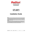
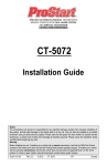
Quick Reference Install Guide
Security and Remote Start for:
Responder HD, LCD, LED, 1-way
Important: If the IVU (control center) has been replaced, all remote controls
must be re-paired with the system. See Remote Pairing for details.
Wiring Connections
RED
For a Spanish or French version of the Installation Guide, please download it from
www.directechs.com under “Resources”.
Adjusting the Sensor
Traducción de los manuales:
Para obtener una versión en Español o Francés del Manual de Instalación, descárguela de www.directechs.com bajo el título “Recursos” (“Resources”).
Adjusting the sensor:
Important! Make sure the vehicle is disarmed. The shock sensor sensitivity can be
adjusted by using a trimmer tool to turn the potentiometer.
Traduction du guide:
Pour une version française ou espagnole du guide d’installation, veuillez le télécharger à www.directechs.com sous «Resources»..
Turn the potentiometer clockwise to increase sensitivity and counterclockwise to decrease sensitivity.
Remote Start, 10-pin heavy gauge connector
Main Harness, 6-pin connector
1
Installation Points
Guide Translations
(+)12VDC CONSTANT INPUT
1
NC
No Connection
(+) FUSED 12V ACCESSORY/STARTER INPUT
2
BLACK
(-) CHASSIS GROUND
2
RED/BLACK
3
BROWN
(+) SIREN OUTPUT
3
PINK/BLACK
(+) FLEX RELAY INPUT 87A key side (if required) of FLEX RELAY
4
WHITE/BROWN
PARKING LIGHT ISOLATION WIRE - PIN 87a of onboard relay
4
PINK/WHITE
(+) IGNITION 2 / FLEX RELAY OUTPUT
5
WHITE
PARKING LIGHT OUTPUT
5
RED
(+) FUSED 12V IGNITION 1 INPUT
6
ORANGE
(-) 500mA GROUND WHEN ARMED OUTPUT
6
GREEN
(+) STARTER INPUT (KEY SIDE OF THE STARTER KILL)
7
VIOLET
(+) STARTER OUTPUT (CAR SIDE OF THE STARTER KILL)
8
ORANGE
(+) ACCESSORY OUTPUT
9
RED/WHITE
(+) FUSED 12V IGNITION 2 / FLEX RELAY INPUT 87
10
PINK
(+) IGNITION 1 INPUT/OUTPUT
Door Lock, 3-pin connector
1
BLUE
(-) 500mA UNLOCK OUTPUT
2
EMPTY
NOT USED
3
GREEN
(-) 500mA LOCK OUTPUT
LIGHT FLASH POLARITY
(10A (MAXIMUM) FUSE JUMPER)
Bitwriter/SmartStart Port
10A FUSE
MINI ATM
RPN: 8540
PINK/WHITE
1 2 3
12 VIOLET/WHITE
BLACK/WHITE
13
24 GREEN/WHITE
INSERTION/WIRE SIDE
Sensor 1
Sensor 2
Neutral Safety
Switch
ON
RF Port
for IVU
Control Center
Main 6-pin
Harness
Auxiliary/Shutdown/Trigger Harness, 24-pin connector
1
PINK/WHITE
2
BLACK/WHITE
3
1 PNK/WHITE
3 5
BLUE/WHITE
2 4 6
INSERTION/WIRE SIDE
RED/WHITE
(-)
23 VIOLET/WHITE
D2D Port (for external
Xpresskit interface module)
Door Lock
Port
Aux/Shutdown/Trigger 24-pin Harness
200mA Ignition 2/Flex OUTPUT
15
GREEN*
(-) DOOR INPUT
16
BROWN/BLACK
(-) 200mA HORN HONK OUTPUT
(-) 200mA TRUNK RELEASE OUTPUT
17
PINK
(-) 200mA IGNITION 1 OUTPUT
18
VIOLET*
(+) DOOR INPUT
VIOLET/BLACK
(-) 200mA AUX 2 OUTPUT
20
BROWN
(+) BRAKE SHUTDOWN INPUT
21
VIOLET/YELLOW
(-) 200mA STARTER OUTPUT
22
GRAY/BLACK
(-) DIESEL WAIT TO START INPUT
(-) 200mA 2ND STATUS /REAR DEFOGGER OUTPUT
24 GREEN/WHITE
4
BLACK/YELLOW
(-) 200mA DOME LIGHT OUTPUT
5
DARK BLUE
1
(-) 200mA STATUS OUTPUT
6
WHITE/BLACK
(-) 200mA AUX 3 OUTPUT
1
7
WHITE/VIOLET
(-) 200mA AUX 1 OUTPUT
8
ORANGE/BLACK
(-) 200mA AUX 4 OUTPUT
12
10
9
8
5
4
3
7
19
2
10
1
1
8
5
6
1
9
GRAY
(-) HOOD PIN INPUT (NC OR NO)
23
ORANGE
(-) 200mA ACCESSORY OUTPUT
10
BLUE
1 TRIGGER
3
(-) TRUNK PIN/INSTANT
INPUT (N/C OR N/O)
24
GREEN/WHITE
(-) 200mA FACTORY ALARM ARM OUTPUT
11
WHITE/BLUE
ACTIVATION INPUT
12
VIOLET/WHITE*
TACHOMETER INPUT
13
BLACK/WHITE**
(-) NEUTRAL SAFETY /PARKING BRAKE INPUT
14
GREEN/BLACK
(-) 200mA FACTORY ALARM DISARM OUTPUT
© 2013 Directed. All rights Reserved.
Learning the Tach (not needed with Virtual Tach)
To learn the tach signal:
1. Start the vehicle with the key.
2. Within 5 seconds, press and hold the Control button.
3. After 3 seconds the status LED on your Control Center lights constant when
the tach signal is learned.
4. Release the Control button.
Important: This unit can learn the tachometer with the analog input or through d2d
using an interface module. The unit confirms which source is used by flashing the
parking lights. When programming tach learning with:
• Analog, the parking lights flash one time.
• D2D interface module, the parking lights flash twice.
If the tachometer input on the system is connected to the vehicle, the d2d tachometer
input is ignored.
Initializing Virtual Tach (not needed with hard-wired tach inputs)
Thermistor/Temp Sensor
Remote Start
10-pin Harness
IMPORTANT! Neutral Safety
switch must be plugged in
and in the ON position
Note: You can test the new setting by cautiously impacting the vehicle with increasing intensity while noting the LED status on the shock sensor. When testing the sensor:
warn away trigger is indicated by a short LED flash and full trigger is indicated by
a longer LED flash.
1
18
10
9
1
12
*
Required connection for manual transmission vehicles.
** Ground this wire for automatic transmission vehicles or connect to the parking brake wire for manual transmission vehicles (see owners guide for manual transmission procedure).
Important: NEVER connect 200mA low current outputs directly to a motor or high
current device WITHOUT a relay
To program Virtual Tach:
1. After the install is complete, remote start the engine. The programming operation may require 3 cranks of the starter before the engine starts and runs.
Do not turn off the remote start if this happens, it is a normal programming
operation.
2. Once the engine begins running, let it run for at least 30 seconds.
3. Using the Remote, send the Remote start command to turn remote start off.
Virtual Tach is programmed.
To reset Virtual Tach, go into the Remote Pairing section of this guide and press/release the Control button 4 times for step #4, then press and hold the Control button
to reset Virtual Tach. Virtual Tach cannot be reset with the Bitwriter.
Note: Virtual Tach cannot be used in MTS Manual Transmission Mode. It is also not
recommended for diesel vehicles.
Virtual Tach handles disengaging the starter motor during remote starting – it does
not address over-rev. If the customer wants to have the over-rev protection capability,
the tach wire must be connected.
Important: After successfully learning Virtual Tach, a small minority of vehicle starters may over crank or under crank during remote start. The Bitwriter can be used fine tune the starter output time in 50 ms increments to
compensate for such an occurrence.
Remote Start Shutdown/Startup Diagnostics
To perform shutdown diagnostics:
1. With the ignition Off, press and hold the Control button (on Control Center).
2. Turn the ignition On and then back Off while holding the Control button.
3. Release the Control button.
4. Press and release the Control button. The status LED flashes to report the last
shutdown for one minute or until the ignition is turned on, as shown in the
following table:
Status LED Flashes
1 flash
2 flashes
3 flashes
4 flashes
5 flashes
6 flashes
7 flashes
8 flashes
9 flashes
10 flashes
11 flashes
Shutdown Mode
Runtime expired
Over-rev shutdown
Low or no RPM
Transmitter shutdown (or optional push button)
(+) Brake shutdown
Hood shutdown
Timer mode/Turbo mode/Manual mode error *
Neutral safety shutdown
Low battery (voltage mode)
Alarm triggered **
Wait-to-start input timed out
*
Timer mode error: Ignition is on or shutdown input is active when activating
timer mode.
Turbo mode error: Turbo mode is programmed off, engine is not on or shutdown input is active.
Manual mode error: MTS mode not enabled.
** Alarm was triggered during remote start sequence.
Startup Diagnostics: If the vehicle fails to activate the remote start, the remote start
module will notify you via parking light flashes on the vehicle to identify the no-start
situation.
Parking Light Flashes
5 flashes
Brake wire is active
6 flashes
Hood pin wire is active
7 flashes
Manual transmission mode is enabled and not initialized.
8 flashes
Neutral safety wire has no ground or the neutral safety switch is Off.
Table of Zones
A zone is represented by the number of status LED flashes used by the
system to identify a particular type of input.
Zone
Description
Input Description
1
Trunk Pin
24 pin Blue wire
2
Instant trigger: a heavier impact
detected by the shock sensor
Shock sensor.
3
Door switch trigger
24 pin Green or Violet wire
4
Instant trigger: For optional sensors
Optional MUX port
5
Ignition trigger
Heavy gauge 10 pin Pink wire
6
Hood Pin
24 pin Grey wire
Bitwriter - Only Options
If programming with the Bitwriter®, the learn routine can be locked or unlocked. If the learn routine has previously been locked, it must be unlocked
with Bitwriter® - this cannot be done manually with the Control button.
The Bitwriter®
gives you access to a wider range of system options. These
features and the adjustments that may be programmed are described under the
Bitwriter section in the full online guide.
Bitwriters with a date code of 6a or older require an IC
upgrade (p/n 998M). Some bitwriters with a date code
of 6B do not require the IC upgrade, refer to tech tip #
1112 for more information.
The Bitwriter® (p/n 998U)
requires chip version 2.7 or
newer to program this unit.
See full Installation Guide for more
detailed information. Such information and more can be found online
at: www.directechs.com
1
Programming System Features
The System Features Learn Routine dictates how the unit operates. It is possible to
access and change most of the feature settings using the Control button.
Open a door.
Turn the ignition on, then off.
Select a Menu. Press and hold the Control button. The number of siren chirps
indicates the menu number. 1 chirp indicates menu 1, 2 chirps - menu 2 and
3 chirps for menu 3.
When the desired menu chirps are heard, release the Control button.
Select a Feature. Press and release the Control button the number of times
corresponding to the feature you wish to change. Then press and hold one
more time to select the features.
Program the Feature. While holding the Control button, you can program the
feature using the remote control.
1.
2.
3.
4.
5.
6.
For features with only two options;
= option 1 while
= option 2.
For features with more than two options;
selects the options in ascending order,
while
selects them in descending order.
AUX
9
Comfort Closure
No Comfort
Closure
Comfort
Closure 1
Comfort
Closure 2
10
Horn Function
Full Alarm
Only
Siren Function 20 ms
Siren Function 30 ms
Remote Start Runtime
12 min.
5
Activation Pulse Count
1
2
6
Turbo Mode
No Turbo
Mode
On-1 min.
On-3 min.
On-5 min.
11
Hood Switch type
Normally
Open
Normally
closed
7
Timer Mode Runtime
12 min.
3 min.
6 min.
9 min.
12
Sensor Full trigger
Single
Double
8
Flex Relay Function
Ignition 2
Accessory 2
Starter 2
13
Door Switch Type
Normally
open
Normally
closed
9
Diesel Start Delay
Wait-to
Start input
Timed 15
sec.
Timed 30
sec.
14
Trunk Switch Type
Normally
open
Normally
closed
10
Accessory during Diesel
Start Delay
On
Off
15
Remote Button unlock
(Ign off)*
On
Off
11
Status 2 Output
Status
Latch Rear
Defogger
Pulse Rear
Defogger
12
Parking Light Output
Constant
Pulsed
Off
13
Anti-grind Output
On
Off
14
Tach Mode Starter
Release
Normal
Increase
Vehicle Temp
Auto Report*
Off
Remote Start Safelock
Off
Siren Function 50 ms
Siren
Function
40 ms
* Not available with the 1-way remote control.
Menu 2 - Convenience
AUX
AUX
Menu
Item
Feature
Opt. 1
Opt. 2
One-time Bypass
One time
bypass
Off
One time
bypass On
Opt. 3
Opt.4
Opt. 5+
15
AUX
Note: Pressing
button resets the feature to the factory default.
AUX
1
Once a feature is programmed:
• Other features can be programmed within the same menu
• Another menu can be selected
• The learn routine can be exited if programming is complete
To access another feature in the same menu:
1. Press and release the Control button the number of times necessary to advance
from the feature you just programmed to the next one you want to program.
2. Then press the Control button once more and hold it.
To select another menu:
1. Press and hold the Control button.
2. After 3 seconds, the unit advances to the next menu and the siren chirps, indicating which menu has been accessed.
The learn routine exits if any of the following occurs:
• The open door is closed
• The ignition is turned On
• There is no activity for 30 seconds
• The Control button is pressed too many times
2
Nuisance Prevention
On
Off
3
Override Pulse count
1
2
4
Door Trigger Error
Chirp
On
Off
5
Ign-controlled Dome
light
On
Off
6
OEM Alarm Disarm
w/Aux-Trunk
On
Off
7
OEM Alarm Disarm
Output
With
Unlock
Before
Unlock
8
OEM Alarm Disarm
Pulses
1
2
16
3
4
5
9
Aux 1 Output type
Validity
Latch
Latch/
reset/ign
30 sec.
Timed
Off (5)/2nd
unlock (6)
Aux 1 Linking
No Linking
Link to Arm
Link to
Disarm
Link to
Arm/
disarm
Link to
Remote Start
only
Aux 2 Output Type
Validity
Latch
Latch
reset/ign
30 sec.
Timed
Off (5)/2nd
unlock (6)
12
Aux 2 Linking
No Linking
Link to Arm
Link to
Disarm
Link to
Arm/
Disarm
Link to
Remote Start
only
Default settings are in bold type.
13
Aux 3 Output Type
Validity
Latch
Latch
reset/ign
30 sec.
Timed
Off (5)/2nd
unlock (6)
Menu 1 - Security
14
Aux 3 Linking
No Linking
Link to Arm
Link to
Disarm
Link to
Arm/
Disarm
Smart Key
Control (Link
to Remote
Start Off)
Feature Menus
1
Opt. 1
Opt. 2
Opt. 3
Opt.4
Opt. 5+
System Arming Mode
Active
Passive Arm
w/o lock
Passive
Arm w/
lock
Auto re-arm
w/o lock
Auto
re-arm w/
lock
2
Panic Mode
On
Ign Off
only
Off
3
Confirmation Chirps
On w/Warn
chirps On
On w/
Warn
chirps Off
Off w/
Warn
chirps On
Off w/
warn
chirps Off
4
Siren Duration
30 sec.
60 sec.
5
Ign-controlled Locks
No Ignlocking
Lock &
Unlock
Lock Only
Unlock
Only
6
Door Lock Pulses
Single
Double
Unlock
Only
Double
Lock Only
Double
Lock &
Unlock
0.4 sec.
7
Door Lock Output
Duration
0.8 sec.
3.5 sec.
8
2nd Unlock
2nd unlock
on Igncontrol after
first unlock
2nd unlock
on Igncontrol with
first unlock
© 2013 Directed. All rights Reserved.
Timed 45
sec.
15
Aux 4 Output Type
Validity
Latch
Latch
reset/ign
30 sec.
Timed
Off (5)/2nd
Unlock (6)
16
Aux 4 Linking
No linking
Link to Arm
Link to
Disarm
Link to
Arm/
Disarm
Link to
Remote Start
Only
17
Aux/Trunk Output type
Validity
Off
2nd unlock
Menu 3 - Remote start
Menu
Item
Feature
Opt. 1
Opt. 2
Opt. 3
Opt.4
1
Transmission Mode
Manual
Automatic
2
Engine Checking Mode
Virtual
Tach
Voltage
Off
Tachometer
3
Cranking Time
0.6 sec.
0.8 sec.
1.0 sec.
1.2 sec.
Opt. 5+
1.4 (5)/ 1.6
(6)/ 1.8 (7)
2.0 (8)/
4.0 (9)
AUX
5.
AUX
AUX
Decrease
To exit pairing mode on the remote:
•
Press and release the
button.
•
Wait 30 seconds without pressing a command button on the remote.
LCD Remote Control:
1. Press and hold the
button for 8 seconds, the remote beeps once,
button.
Main Menu is displayed. Release the
2. Press the AUX or
buttons until Pair is displayed.
3. Press and hold the
button until the remote beeps 3 times then release the
button. The remote is now ready to pair with the system.
4. Press the
button.
5. Wait several seconds for feedback as the remote generates a security encryption and sends it to the Control Center. If pairing is successful the siren chirps
and the remote emits several tones. The screen displays if the Pairing is successful or failed with corresponding text. If pairing fails repeat step 4.
AUX
AUX
AUX
On
AUX
On
Reset and Delete
To reset the features/virtual tach or delete remote controls follow this procedure:
1. Open at least one vehicle door
2. Turn the key to the ON position
3. Within 5 seconds press and release the control button: 2 times to delete remotes, 3 times to reset the features to default or 4 times to reset virtual tach.
4. Once you have selected the function step, press the control button once more
and hold it. The LED will flash and the siren will chirp to confirm the functional
step chosen. Release the control button.
5. Press the
button of a programmed remote control. The siren will chirp confirming the feature has been reset/deleted.
Remote
Start Only
Toggle the menu wheel until the Adjustments screen appears.
Press in on the menu wheel to enter.
In the Adjustments menu highlight Remote Pair and press in the menu
wheel to go to the screen. Follow the on-screen instructions:
i. Press and hold the
button until tones are played.
ii. The siren chirps to indicate the system has learned the remote ID and is
sending its ID to the remote
iii. Release the
button.
Successful or failed pair: The HD remote control indicates a successful or failed
pairing and returns to the Adjustments menu. If pairing fails, the remote will
go back to the Remote Pair screen, press the
button again to attempt
another pairing.
On- 10 min.
AUX
10
Feature
60 min.
* Not available with the 1-way remote control.
11
Menu
Item
24 min.
2.
3.
4.
4
AUX
AUX
To exit pairing mode on the remote:
•
Press and release the
button.
•
Wait 30 seconds without pressing a command button on the remote.
Responder LED or Companion Remote Control:
1. Press and hold the
button for 8 seconds. The transmit LED will come on
solid. Release the
button.
2. Press and hold the
until the transmit LED flashes 3 times then comes on
solid.
3. Press the
button.
4. Wait several seconds for feedback as the remote generates a security encryption and sends it to the Control Center. If pairing is successful the siren will chirp
and the 2-way remote will emit several tones (the companion remote does not
generate tones). If pairing is not successful press and release the
button
once and then repeat steps 2 and 3.
AUX
AUX
AUX
AUX
Note: Deleting a remote control does not reset the features or virtual tach, resetting
the features does not delete remote controls or reset virtual tach. The Zap feature on
the Bitwriter will not reset the virtual tach setting.
AUX
AUX
Reset/delete will exit if:
• The ignition is turned off
• The open door is closed
• 60 seconds lapses with no actions.
Remote Pairing
Prepare the vehicle system to be Paired with a new remote
1. Open at least one vehicle door.
2. Turn the key to the ON position.
3. Within 5 seconds press and release the Control button on the Control Center
one time.
4. Within 5 seconds, press and hold the Control button on the Control Center.
The status LED begins flashing in single flash sequence and the siren chirps
once to confirm the system is ready for remote pairing. Release the button.
5. Locate your remote control model below and follow the instructions.
System Pairing will exit if:
• The ignition is turned off
• The open door is closed
• 60 seconds lapses with no actions
Note: Make sure the remote to be paired with the system is set for the desired Car
1 or Car 2 operation.
HD Remote Control:
1. With the HD remote screen blank, press in and hold the menu wheel (located
on the side) for 3 seconds until the
screen appears.
Settings
To exit pairing mode on the remote:
• Press and release the
button once, then press and hold until the transmit
LED shuts off.
• Wait 30 seconds without pressing a command button on the remote control.
AUX
AUX
AUX
Basic Remote Functions
Level
Button
AUX
AUX
AUX
UX
AA U
X
DIRECT
ACCESS
X1
AUX
X2
AUX
X3
X4
ARM
SILENT ARM
SENSOR BYPASS
ARMED (SILENT
SENSOR)
ARMED (SILENT
TRIGGER)
DISARM
SILENT DISARM
VALET MODE
CAR FINDER
REMOTE START
RUNTIME RESET
TIMER MODE
SMART START
REAR DEFOGGER
TRUNK RELEASE
AUX 1
AUX 2
AUX 3
AUX 4
FUNCTION SHIFT
CABIN TEMPERATURE REQUEST
(2-WAY ONLY)
RUNTIME CHECK
(2-WAY ONLY)
LAST TRIGGER
REQUEST
(2-WAY ONLY)
Note: See Owner’s guide for your specific model for more details. The above table
is applicable to LCD, LED and Companion remote controls only, but not HD.
QRN5X06 2013-08
2
AUX