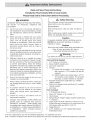
1
Read and Save These
Installation
Please
Read
Must
Instructions
Compmy With
Entire
]:nstructions
atomLocam Codes
Before
Proceeding
f
f
Safety
WARNING
Warning
TO REDUCE THE RISK OF FIRE, ELECTRIC SHOCK,
OR INJURY TO PERSONS, OBSERVE THE
FOLLOWING:
Turn off power circuit at service panel and lock out
panel before wiring this appliance.
A.
With internal blower: :[20V AC, 60Hz. :[5A Branch
Circuit.
B.
C.
Use this unit only in the manner intended by
the manufacturer. If you have questions, contact
the manufacturer. (Bosch Service: 800-9442904.
Before servicing or cleaning the unit, switch
power off at service panel and lock service
panel. This will prevent power from being
switched on acddental[y. When the service
panel cannot be locked, securely fasten a
prominent warning device, such as a tag, to
the service panel.
R
Due to the size and weight of this unit, two
installers are recommended.
When cutting or drilling into wall or ceiling, do
not damage electrical wiring or other hidden
utilities.
O. To properly exhaust air, be sure to duct air
outside. Do not vent exhaust air into spaces
within walls, ceilings, attics, crawl spaces, or
garages.
H. Install this hood in accordance
with all
requirements
I.
,.
With remote blower (DAH95 models only): :[20V AC
60Hz. :[5A Dedicated Branch Circuit.
Caution
For general residential kitchen ventilating use only.
DO NOT use to exhaust hazardous or explosive
materials or vapors.
Caution
Vent unit to the outside unless using redrculation
Note: If using redrculation kit, refer to
instructions included with that unit.
Installation work and electrical wiring must be
done by qualified person(s) in accordance with
all applicable codes & standards, including firerated construction.
D. Sufficient make-up air is needed for proper
combustion and exhausting of gases through
the flue (chimney) of fuel burning equipment
to prevent back=drafting. Follow the heating
equipment manufacturers guideline and safety
standards such as those published by the
National Fire Protection Association (NFPA), the
American Society for Heating, Refrigeration and
Air Conditioning Engineers (ASHRAE), and the
local code authorities.
E.
REQU[REHENT:
specified.
Ventilator hood assembly models DAH93 and
DAH94 must be installed
with blowers
DHG4001UC (included).
Model DAH95 must
be installed with integral blowers DHG400:[UC
or DHG6001UC or remote blowers DHG6003UC
or DHG:[006UC.
Other ventilator
blowers
CANNOT be substituted.
kit.
Warning
reduce the risk of fire, use only metal ductwork_)
Tools and Parts Needed_
:[.
2.
3.
4.
:[/2" Conduit wi Connector
Blower (DAH95 models only)
Duct Cover (optional)
Ducting:
a) DAH93 and 94 models: 7" (8" is also acceptable, however a 7"-8" transition will also be
required)
b) DAH95 models with remote blower: :[0" (7"=
:[0" transition is also needed. For horizontal
discharge, a custom transition is required.)
R20 50W Incancescent Light Bulbs (2), installed
(DAH93 models)
6. 50W Par 20 Halogen Flood Light Bulbs (2), installed
(DAH95 models)
7. Duct Tape
Parts Included:
5.
:[.
4 #8 Sheetmetal Screws
2.
3.
4.
5.
6.
Filters (30" models: 2, 36" models: 3)
Hood Canopy
Remote Blower"Pigtail" Adaptor (DAH95 models only)
7" Transition
Spring Type Wire Nuts (rated for a minimum of (2)
#:[8ga wires and a maximum of 4 #:[4ga wires, UL &
CSA rated to 600V and 3020 F/ :[500 C.)
Toggle Bolts (2)
6 (30" models) or :[2 (36" models) Blunt-Nosed
Sheetmetal Screws
7.
8.
j
This unit is approved for use with all residential appliances. For residential use only.
Note: The Bosch ventilation hood referred to throughout this manual is manufactured by BSH Home Appliances Corporation.
General
Znformation
!.
For the most efficient air flow exhaust, use a straight
run or as few elbows as possible.
2.
Do not use flex ducting.
3.
COLD WEATHER installations should have an additional
Blower Cord Connector
Connector Access Panel
backdraft damper installed to minimize backward cold
air flow and a nonmetallic thermal break to minimize
conduction of outside temperatures
as part of the
ductwork. The damper should be on the cold air side of
the thermal break. The break should be as dose as
possible to where the ducting enters the heated portion
of the house.
4.
Hood installation height above cooktop is the user's
preference. The lower the hood above the cooktop, the
more efficient the capturing of cooking odors, grease,
and smoke. This hood has been approved for installations
as low as 24 inches and as high as 36" above the cooktop.
The lower height may be inconvenient for tall people
and large cooking vessels. Consequently,
Bosch
recommends the hood be installed 30"-36" above the
Rear Filter Rail
] Box
Figure
2 - DAHgB
models
with
internal
blower
Blower Cord Connector
countertop.
5.
Remote blowers require a five wire installation.
6.
Make-Up Air: Local building codes may require the use
of make-up air systems when using ducted ventilation
systems greater than specified CFM of air movement.
The specified CFM varies from locale to locale. Consult
your HVAC professional for specific requirements in your
area.
Zo Unpack
Remove
] Box
Knockout
Mounting
Remove the appropriate blower duct knockout. For
horizontal discharge, remove the knockout in the back
wall of the hood. For vertical discharge, remove the
knockout in the top of the hood.
3, Znstall
Blower
Hood
Pull hood from outer packaging and remove all
packaging materials.
®
Connector Access Panel
Zntemal
Blower
Plate
Figure 3 - DAHgS models with remote
Rear Filter Rail
blower
Remote Wire Cover
(DAH95 models only)
If your hood is already equipped with a blower, or you
will be using a remote blower, proceed to
Step 4: Install Transition (next page),
!. Remove rear filter rail.
2.
Remove blower control wire cover,
3.
Remove 3 box.
4.
With hood standing on its back wall, place blower
in center of hood.
5.
Screw 6 screws (3 on each side) through mounting
plates. See Figure 2.
White Connector
] Box
Rear Filter Rail
4.
nstall
are :[5 3/4" from the center line (See Figure 5).
Transition
For i_ternai bJower installation, install the 7"
transition (included) to connect to 7" ducting. If 7"
ducting is not available, 8" ducting may be used. In
this instance, an additional 7=8" transition must also be
used (not included).
4,
Place the hood.
5,
Tighten the screws,
For remote blewer applications, 10" ducting is
required. In this instance, a 7"=:[0" transition must
also be used.
Attach the transition with 4 #8 sheetmetal screws
(included) and seal connection with duct tape,
®
Mount
the
Figure 4 - Wall Mount
Hood
The DAH model hood can be mounted through the
back wall or through the top. See General Information,
page :[, for suggestions for hood height.
Once the preferred height is determined, locate the
centerline (left to right) of the cooking appliance,
Wall Meunt
:[.
lB 3/8"
flom
CL
From the centerpoint of the cooking appliance,
measure up to the preferred height. Measure up an
additional 9" to locate the centerline of the screw
holes (see Figure 4).
"_ 36"
2.
Install toggle bolts through drywall leaving :[/4" of
the bolt exposed.
I30
I
from
CL I
I
Install one togglebolt :[:[ :[/2" to the left of the
centerline and one togglebolt :[:[ :[/2" to the right
of the centerline. These are the only installation
points for the 30" hood. See Figure 4
For the 36" hood, there are 2 additional installation
points. These are also at the centerline height, but
are :[5 3/8" from the centerline in each direction.
See Figure 4.
3.
Place the hood by sliding the mounting holes in the
hood over the bolts.
4.
Tighten the bolts.
I
Top Meu_t
1. Install the hood flush against the back wall.
2.
3_
Figure 5 - Top Mou_t
CL
Identify the centerline on the mounting surface
(underside of cabinet).
Front
Place the hood and install the drywall screws
through the mounting holes.
Insert 3 drywall screws :[:[ :[/2" off the
centerline in both directions at the following
depths:
:[.
2 :[/4" from
the back wall
2.
8 :[/4" from
the back wall
3. 9 :[/4" from the back wall
(See Figure 5).
21/4
I
The 36" hood also requires 3 additional screws, at
the same depths, on each side (total of 6). These
Back
4
6. Connect
Accessories
Wiring
f
WARMING:
Use only spring type wire nuts (included) to make
electrical connections. Replacement wire nuts must be
rated for a minimum of (2) #!8ga wires and a maximum
of 4 #!4ga wires, UL A CSA rated to 600V and 3020 Fi
!500 C. Request #189692 when ordering from
BSH.
For Internal
Blower
The following accessories are available from your Bosch
dealer or through Bosch Service: 800-944-2904. Please
reference the model number when requesting these items.
Use:
See Figure ! or 2, page 3.
!. Remove electrical knockout behind ] box and
install !/2" conduit connectors.
2.
Run !20V AC 60Hz, !5A supply wires through !/2"
conduit to hood electrical knockout behind ] box
cover
3.
Connect blower cord wires to house wiring through
electrical knockouts. Use wire nuts supplied (white
to white, black to black, green to green).
4.
Connect blower cord at white connector behind
6" Duct Covers
Biscuit
Black
Stainless Steel
White
"
30"
'
36"
DCZ7607UC
NiA
DCZ7606UC DCZ9666UC
DCZ7605UC DCZ9665UC
DCZ7602UC DCZ9662UC
12" Duct Covers
Biscuit
Black
Stainless Steel
White
Recirculation Kit
Biscuit
Black
Stainless Steel
White
Charcoal Filter
°
30"
"
36"
DCZ7207UC
NiA
DCZ7206UC DCZ9266UC
DCZ7205UC
DCZ7202UC
30"
DRZ7007UC
N/A
DRZ7006UC DRZ9066UC
DRZ7005UC DRZ9065UC
DRZ7002UC DRZ9062UC
DHZ7960UC
DHZ3410UC
connector access panel (if not already connected).
Verify that connectors are tightly connected.
For Remote Blower Use:
3 i 4 x!OTransition
Blowers*
Integral Blower, 400 CFH
DHG4001UC
See Figure 3, page 3.
!. Remove 2 hood electrical knockouts and install
!/2" conduit connectors.
Integral Blower r 600 CFM
Remote Blower, 600 CFM
Remote Blower, 1000 CFM
DHG6001UC
DHG6003UC
DHG1003UC
2.
Run black, white and green supply wires through
!/2" conduit to hood electrical knockout behind
] box.
3.
Connect power supply wires to hood wires behind
] box (white to white, black to black, green to
green). Use wire nuts supplied.
4.
Run 5 wires (#!4 AWG) in !/2" conduit from the
remote blower to the electrical knockout behind
the remote wire cover.
5.
Connect remote blower wiring to"pigtail" wires
behind remote wire cover with wire nuts supplied
(white to white, black to black, green to green and
black to brown, white to white, red to red and
blue to blue) See Figure 6.
6.
*for use with DAH95 models onl
Figure 6 - Remote Blower Pigtail
Assembly
N GND L1
i
_
BLACK
WHITE
Connect other end of "pigtail" at white connector.
Verify that connectors are tightly connected.
BROWN
RED
®
DCZ9265UC
DCZ9262UC
36"
Reassemble
Hood
,
Reattach the following:
1. Connector access panel (internal blower only)
2. J box
3. Remote wire cover (remote blower use only)
4. Back filter rail
5. Filters
5
BLUE
\
555! McFadden Avenue, Huntington Beach, CA 92649 • 800/944-2904
5060008728 Rev. A (ECO# 5V0iMD)
© BSH Home Appliances Corporation 2003 • Litho U. S. A. 8/03