1
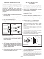
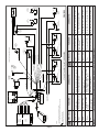
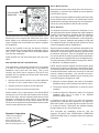
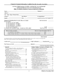
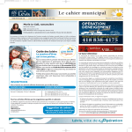
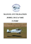
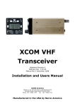
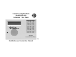
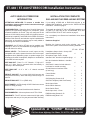
ST-440 / ST-640 STEREOCOM Installation Instructions
AUTO SQUELCH STEREOCOM
INTRODUCTION
INSTALLATION FOR COMPLETE
SAS-440/640 PLUS RMS-440/640 SYSTEM
ATTENTION INSTALLER: To assure a trouble free
installation, please read the entire instructions through
once before beginning.
If just adding a RMS-440 or RMS-640 switcher to an
existing SAS installation, proceed to the “INSTALLATION
RETROFIT” section on page 5.
CONFIGURATION - Sigtronics Auto Squelch Stereocom
systems are specifically designed for permanent, panel
mounted installation in aircraft. They are configured in two
sections: A SAS-440 (4 place) or SAS-640 (6 place) intercom
with transmit capability, and a RMS-440 or RMS-640 Stereo
Switcher. Both intercom and switcher may be installed at the
same time, or the switcher section may be easily added to
an existing SAS intercom installation.
To upgrade an existing ST-400 or ST-600 installation to a
ST-440 or ST-640, skip to the “UPGRADING A ST-400
INSTALLATION TO A ST-440” section on page 5.
UPGRADE - An ST-440 or ST-640 can be installed in an
existing ST-400 or ST-600 installation by swapping the units
out and minimal re-wiring.
MUSIC INPUTS - The Stereocom music inputs are fully
compatible with music systems that have line level output,
headphone level (Walkman) output, or speaker output up to
25 watts per channel. No amplifiers, adapters or modifications
to the RMS unit are required.
SIZE SAS UNIT - Panel 1” x 2.5”. Chassis - 1” high x 2.5”
wide x 6” deep. Can be mounted either horizontally or
vertically in the aircraft panel.
SIZE RMS UNIT - A 4” x 2.9” x 2” chassis mounted
remotely.
WEIGHT SAS UNIT - 6.4 ounces (SAS-440 intercom unit
with panel and knobs). Jacks and wiring harness weigh 5.5
ounces.
WEIGHT RMS UNIT: 7.5 oz. (RMS-440).
INPUT POWER - 11VDC through 32VDC. Maximum current
drain 0.15 Amp (ST-440).
DISTORTION - Less than1%total harmonic distortion.
ENVIRONMENTAL - Meets requirements of TSO-C50b.
WARRANTY - The ST units are constructed of high quality
components and carry a five year parts and labor warranty.
For a completely new Stereocom installation follow these
instructions:
Hardware Supplied
Besides the intercom and music switcher unit, each
Stereocom system comes with the following hardware:
ST-440
ST-640
Headphone Output Jacks - Accept .250”
stereo headphone plugs.
4
6
Microphone Input Jacks - Accept
standard .206” aircraft microphone plugs.
4
6
Mic Jack Insulation Washers - shoulder
and flat.
4
6
SAS Panel: Lettered on both sides for
horizontal or vertical mounting.
1
1
Aircraft/Intercom Interface Cable
(4 feet long).
1
1
Control Knobs
2
2
Switch Nuts
2
2
SAS Mounting Screws 4-40
2
2
SAS Drill Template (Hole Size Pattern).
1
1
Music Input Cable
1
1
Music Switch Harness
1
1
Music Switch Panel
1
1
Music Input Jack, 3.5 mm
1
1
RMS Mounting Screws 6-32
4
4
RMS Mounting Nuts 6-32
4
4
Specialists in “SOUND” Management
178 East Arrow Highway, San Dimas, CA 91773 ( 909 ) 305-9399
SAS-440/640 CHASSIS INSTALLATION
The location selected requires a minimum front panel area
of 2 1/2” by 1 1/16”. Depth required behind panel is 6” plus
cable access. Allow approximately 1” by 1 1/2” space nearby
to mount the music switcher panel.
CAUTION: Move aircraft flight controls through limits
of travel while observing selected area to make certain
intercom components will not interfere with aircraft control
components.
Panel Preparation:
1. Position the adhesive drill template on the aircraft panel
in the selected area.
2. Center punch each hole at cross lines. (The five holes
are in a straight line and equally spaced 0.4” apart).
3. Drill a 1/8” pilot hole in all five places.
4. Enlarge one hole to 1/2” and two holes to 3/8” per
template.
��������
�����
1. As in mounting the intercom, select a mounting location
which will not cause interference with flight controls.
(Mount the RMS Switcher unit within 3 feet of the SAS
intercom to allow connection of J1 and P1).
2. Remove the four corner (smaller) panel screws and
remove the RMS unit from its chassis.
3. Drill four mounting holes in the aircraft with same hole
pattern as in the switcher chassis. Use a #27 drill.
(Clearance drill for 6-32”)
4. Secure the chassis to the aircraft with the four 6-32
screws and nuts provided. The screw heads should be
inside switcher chassis for circuit board clearance. (Care
should be taken not to crush grommets while applying
torque to screws.)
5. Replace the RMS unit in the chassis and secure.
SWITCHER HARNESS INSTALLATION
1. Select an area on the aircraft panel and drill 1/4” diameter
holes for the PILOT and PASS. MUSIC ON/OFF
Switches.
��������
�����
2. Mount the switches with the bushing key slots down. The
PILOTS switch has a WHITE/BROWN wire going to it and
mounts on the left.
����
�� ��� ������
����� ����
RMS-440/640 SWITCHER CHASSIS
INSTALLATION
���� � ��� ������
3. Place the printed switcher panel over the switch bushings
and install and tighten the two switch nuts.
����
��������
Figure 1
4. Route the cable harness to the Switcher unit clear of
aircraft controls. Secure with suitable wire ties.
Mounting Chassis: See Figure 1
1. Remove the knobs from the Volume and OFF/ALL/ISO
controls using a 0.050 inch Allen wrench. NOTE: DO
NOT REMOVE the nuts from the Volume, Squelch, or
OFF/ALL/ISO controls.
2. Insert the SAS unit from rear of the aircraft panel with the
appropriate arrow on the unit chassis pointing upwards.
3. Install the printed SAS panel and lightly thread the two
4-40 screws through the holes in intercom panel. The
nuts on the Volume and OFF/ALL/ISO controls should
fit inside the 3/8” diameter holes.
4. Tighten the two screws.
5. Put the knobs on the Volume (VOL) and OFF/ALL/ISO
control shafts and tighten the Allen screws.
���
��������
������
����
���������
������
����
�����
������
���
������
����
��������
�����
Microphone Jack
Figure 2
MOUNTING HEADPHONE AND
MICROPHONE JACKS
1. Locate the mounting areas. (One mic and one headphone
jack required for each headset).
2. Drill 3/8” diameter holes for headphone jacks and
install. The terminals on the stereo phone jacks may be
identified per the mic jack shown in Figure 2. The phone
jack bushings (sleeve terminal) must be grounded to
airframe or wired to aircraft ground.
page 2
page 3
���
���
���
�������� �������
��
���� �
���� �
����� �
����� �
����
������
�����
��
�������� ������
������ ������
������� ������
�������� ������
������ ������
����� ������
������ ������
��
���� �
�������� ������� ������
�� ����� �� � ��
��������� ������
Black
Brown
Red
3
4
6
7
TABLE 1
Blue
2
������� ����
��
�
CONNECT TO:
Pilot Transmit Switch (PTT) & Radio Key
Input. Switch to Ground to Transmit.
Ring Terminal of Hand Mic Jack or Mic
Input of Radio or Audio Panel
Intercom Circuit Breaker
Power Input (12
through 28 VDC)
Aircraft Chassis Ground – Central
Grounding Point “A”
14
13
11
10
9
8
J2
PIN
Tan
�
���
�
�
��
������
���
��������
��� ����
��
��������
��� ������
�����
������ �
����
�
Ring Terminal of Passenger #1 Mic Jack
CONNECT TO:
��������
��������� ����
������
����
��
�����
��� ������
����� ��� ���
�������� �����
Co-Pilot Mic Input
Co-Pilot Transmit
Switch Input
Ring Terminal of Co-Pilot Mic Jack
Co-Pilot Transmit Switch (PTT)
* 6 Passenger #4 Mic Input Ring Terminal of Passenger #4 Mic Jack
* 6 Passenger #3 Mic Input Ring Terminal of Passenger #3 Mic Jack
White / Orange
Tan
��
��������
���� ���
����
���
��� �����
��������� �����
* 6 Passenger #2 Mic Input Ring Terminal of Passenger #2 Mic Jack
White / Blue * 8
Tan
FUNCTION
��������� �
�
������
���
��� ����
�����
��� ����
����
��
������
���
����
* 6 Passenger #1 Mic Input
WIRE COLOR
Tan
���
����
��������
���������
����
��������� ����
������
����
������������� ������������ �������
��� ����
������
���
������ ���
������� ������������
������� ����������
������ ���������
������ �����
������ �����������
������
���
�����
��������� ����
����
������ ����
���
����������������� ��������� ����
* See corresponding number paragraphs under the “WIRING INSTRUCTIONS” section starting on page 4.
*5
����
���������
�������
������
������
����� �
��������� �
������ �����
Transmit Mic Audio
Output
* 4 Intercom Ground
���
��������� ����
������
����
������ �����
������ ����
�� ����� �� ��� �����
�� ����� �� ��� �����
������� ����
������ �����
������ ����
Ring Terminal of Pilot Mic Jack
�� ��
���
��������
�������
�������
�� ����
�� ��������
����� ����
����� ���
* 3 Radio Headphone Input Radio Headphone Output
Pilot & Radio Transmit
White / Red * 8
Switch Input
Pilot Mic Input
FUNCTION
White / Black
WIRE COLOR
1
J2
PIN
� �������� �� ������ ����� �����
��
��
������� � �������
����� �������� ����
��
��
���
��
��
�� �� ��� ��� ��� ������� �� ������ ���� ��� ������ ������ ������
�� ����� �������� ���� ������� �������� �����
������
������� � �������
��������
���
������
�������
������
��
���������
��
���� �����
������
���� �
����
������ ���
����� ��������
�����
������ ���
3. Drill 1/2” diameter holes for mic jacks and install with
insulating washers supplied. (See Figure 2) Note: If the
aircraft already has headset jacks (not including the hand
mic jack), they can be used for this system, however, any
existing wires must be removed and the jacks must be
wired as shown in Figure 3. Additionally, if any existing
mic jack is mounted in metal, insulating washers must be
installed and the barrel connection wired back to Point
“A”.
channel maximum). Use the Violet, Black, and Orange
wires for a Line Level or Headphone Level (Walkman)
output. A small stereo panel mount music jack is provided
for portable stereo input, if desired. Connect the Violet,
Black, and Orange wires to the jacks terminals as shown
in Figure 4. Drill a 1/4 inch hole and mount the jack on the
aircraft panel. To use, connect an adapter cable between
the music input jack and the output of the portable stereo.
Suitable cables are available at your local Stereo or
electronics store as well as from Sigtronics.
WIRING INSTRUCTIONS
1. Connections should be made as shown in Figure 3 and
Table 1 on page 3.
2. If longer wire lengths are required, use a good quality
hookup wire - 22 gauge or larger. Although not necessary,
shielded audio wire can be used if desired. This can
simplify the wiring process.
3. The blue wire from J2 Pin 3 must be connected to the
aircraft radio headphone output - NOT the speaker
output.
4. Connect all intercom mic jack grounds to a single aircraft
chassis ground point - Point “A” - as shown in Figure 3.
(Use the black washers supplied to insulate the intercom
mic jacks from aircraft chassis ground). NOTE: this
intercom central grounding point is used to eliminate any
unwanted electrical noises, such as alternator whine
or strobe noise, from being induced into the intercom
system through the grounds. All intercom mic jack barrels
must be insulated from ground where they are mounted
and connected back to Point “A” on their own individual
ground wire. Similarly, both intercom ground wires (J2
pin 4) and the push-to-talk switch grounds must also be
connected back to Point “A”. It is not necessary, however,
to connect the headphone jack barrels to Point “A”. They
can either be grounded where they are mounted or some
place nearby.
5. The red wire may be connected to either 12V (14V) or
24V (28V) power source. No switching or adjustments
are required to operate from either source.
6. Tan wires (J2 pins 8, 9, 13, and 14) are only used on
installations that require extra intercom positions. Tan
wires pins 13 and 14 are provided on ST-640 units only.
7. Do not cut and shorten J1 cable. Coil and secure any
excess cable.
8. The wires used in the
stereo music input
cable (J3) depends
on the type of stereo
used. Use the White/
Violet, White/Brown,
Yellow, and White/
Yellow
wires
for
stereos with speaker
outputs (25 watts per
Figure 4
�������� �����
���
���
�������
9. A Sigtronics Stereocom system can be installed for use
with monaural general aviation type headsets. Follow the
installation instructions as normal except for the wiring of
the stereo headphone jacks. Use the stereo headphone
jacks supplied with the Sigtronics Stereo Switcher but
leave the “RING” connections open. Connect both
headphone wires to the “TIP” of the respective jacks P4 cable GRAY and GREEN for the pilot, and BLUE and
WHITE for the copilot and passengers.
10. Make sure any unused wires are properly insulated and
kept from shorting to any other wires or aircraft ground.
Skip down to the “INSTALLATION CHECK OUT AND
ADJUSTMENT” section on page 5.
INSTALLATION RETROFIT
1. Mount the RMS switcher chassis per the “RMS-440/640
SWITCHER CHASSIS INSTALLATION” instructions on
page 2.
2. Install the PILOT and PASS. MUSIC ON/OFF PILOT/ALL
Switches and route the harness per the “SWITCHER
HARNESS INSTALLATION” instructions on page 2.
3. Unplug the SAS unit from its wiring harness and insert
connectors J1 and P2 on the RMS unit as shown in Figure
3. Connect remaining plugs per Figure 3.
4. Remove the intercom headphone jacks from the pilot,
co-pilot, and passenger positions in aircraft. Wires,
which had been connected to the phone jacks should be
cut, insulated and tied back. If two or more wires appear
on a single jack terminal, they should be cut free of the
jack, then spliced together before insulating and tying
back. Do not disturb the microphone jacks. Replace
headphone jacks with three terminal type “stereo” jacks
supplied with the RMS switcher. Connect wires to the
stereo jacks per Figure 3. Terminals on the stereo phone
jacks may be identified per the mic jack shown in Figure
2. The jack bushings (barrel terminal) must be grounded
to the airframe or wired to aircraft ground. For monaural
operation See Note 9 in the “WIRING INSTRUCTIONS”
section above.
5. Connect up stereo music source per Figure 3 and Notes
8 and 10 under the “WIRING INSTRUCTIONS” section
above.
����
������
������
��������
Skip down to the “INSTALLATION CHECK-OUT AND
ADJUSTMENTS” section page 5.
page 4
UPGRADING A ST-400 INSTALLATION TO A ST-440
Intercom Chassis Mounting
The SAS unit is specifically designed to easily replace a
SPA. The panels are exactly the same dimensions (1” x 2.5”),
however the SAS units are 1 3/4” longer than the SPA units.
Make sure that you have the extra depth required behind
your panel. The five mounting holes are exactly in the same
positions. Only the center hole will have to be changed
(enlarged from 1/4” to 1/2”).
To upgrade, first remove the SPA unit from the aircraft panel.
This is done by unscrewing the two Phillips head screws and
the nut on the ON/OFF switch. Remove the printed SPA
panel. Pull the SPA unit out and unplug the white connector
from the RES cable. Next, drill the center hole in the aircraft
panel out to 1/2”. Then to mount the SAS chassis per the
“Mounting Chassis” instructions on page 2.
Unplug all four connectors going to the RES switcher unit.
Remove the RES unit from its mounting chassis by removing
the four corner screws. Remove the RMS switcher unit from
its chassis similarly. Put the RMS switcher into the RES
chassis and secure.
Disconnect the RES music input cable (J3) from the music
source and install the RMS input cable per Notes 8 and 10
under “WIRING INSTRUCTIONS” on page 4.
Remove the RES switch harness and Panel by removing
the two 1/4” nuts on the switch bushings. Disconnect the
wires from the intercom stereo headphone jacks. Install the
RMS switch harness and Panel per paragraphs 2, 3, and 4
under the “SWITCHERHARNESSINSTALLATION” section
on page 2.
Rewire all the stereo headphone jacks per Figure 3.
INSTALLATION CHECK-OUT AND
ADJUSTMENTS
After the system is installed, again check that the SAS and
RMS unit chassis, jacks, and wiring harnesses are clear of
all aircraft operating controls and cause no interference with
them. Check out the Stereocom installation by following the
instructions:
Plug in all the headset mic and phone plugs into the
respective intercom jacks. Put on the pilot’s headset and
position the boom mic close to the mouth, as is the practice
with a hand-held mic. Voice clarity is best when the mic is at
one side of the mouth and 1/4” from the lips.
the Stereocom system was installed. Aircraft radio reception
should be heard in the pilots headset. Aircraft radio reception
should not be heard in the co-pilot or passenger headsets.
There should be no intercom between headsets with the SAS
unit turned “OFF”.
Next turn the SAS unit OFF/ALL/ISO switch to the “ALL”
position. Set the SAS volume control to mid-position. Verify
that all headset positions can now intercom with each other,
including the passengers. Verify that both pilot and co-pilot
can operate the aircraft radio(s). In this mode all headsets
on the intercom will hear the aircraft radio(s).
It may be necessary at this time to adjust the SAS unit
transmit mic output to the aircraft radios. A small adjustable
potentiometer is provided inside the unit for this purpose. It
is accessible through a hole in the side of the SAS chassis.
It is marked “MOD. ADJ.”, and can be adjusted with a small
blade screwdriver. In the event of over-modulation (garbled)
or reports of weak transmission’s over the aircraft radio, an
appropriate adjustment can be made. Clockwise rotation
increases the output level to the aircraft radio mic input.
Counter-clockwise rotation decreases modulation level.
This adjustment sometimes needs to be made after the initial
installation of the intercom or if a new radio is installed. (The
output is set for unity gain at Sigtronics).
To verify music operation, connect your music source to the
music input jack, if applicable. Turn on the music source
and set volume to low level. Next turn “ON” the PILOT and
PASSenger Stereocom MUSIC ON/OFF switches. When the
aircraft radio and intercom are quiet you will hear music in the
headsets. Adjust the music source volume to a comfortable
level. Verify that music is heard in all headsets and is
interrupted by intercom conversations. If everything checks
out, refer to the ST-440/ST-640 STEREOCOM OPERATING
INSTRUCTIONS for proper use and other operating modes
of the Sigtronics Stereocom system. If something does
not work as described, carefully go over the system wiring
again. If ok, refer to the following section for helpful hints and
solutions to common problems:
HELPFUL HINTS AND TECHNICAL
INFORMATION
SAS-440/SAS-640 Sidetone Modification
Most aircraft radios, when transmitting, provide what is called
“sidetone”. Without sidetone, you will not hear yourself or your
co-pilot transmit to ATC. This can be distracting, especially
during instruction, because no one on the intercom will
hear the outgoing transmission of the radio conversation.
Some aircraft radios, however, do not provide this function.
Also, some radios are designed to drive only one headset.
Therefore, if you have such a radio, the sidetone may be
extremely weak or nonexistent.
To assure that the aircraft radios, pilot’s headset, and PTT
switch are connected and functioning properly, turn the SAS
units OFF/ALL/ISO switch to the “OFF” position. Turn the
PILOT and PASSenger MUSIC ON/OFF switches “OFF”.
If applicable, set the aircraft audio panel to “Headphone” If this is the case and the sidetone cannot be turned up in
position. Then turn on the aircraft radio(s) as usual, and the radio(s), a simple modification can be performed within
verify that the pilot can hear the radios and can transmit the SAS unit to simulate sidetone. The SAS requires partial
using his push-to-talk switch and headset. Aircraft radio(s) disassembly to accomplish this modification. First unplug and
and audio panel should operate exactly as they did before remove the SAS unit from the aircraft. To disassemble unit,
page 5
Stereo Music Systems
Most automotive stereo units operate from 12V-14V sources.
Regulators or converters are available to permit operation
from 24V-28V sources.
��� ���������
������ ����
Some FM receivers are capable of causing interference with
aircraft COM and NAV receivers. The aircraft panel should
be placarded accordingly. Most player only units (cassette or
CD) do not cause interference with aircraft receivers.
Stereo Headsets
Figure 5
carefully remove the four screws securing the bottom cover.
Remove the cover to expose the solder side of the circuit
board. Solder in an insulated jumper wire as illustrated in
Figure 5. Replace the cover and the four screws to complete
the modification.
With the unit modified in this way, the intercom VOLume
control adjusts the level of the sidetone. Additionally, when in
“ISO” or “OFF” mode, the SAS unit will not provide sidetone
even with this modification.
Install the SAS unit into the aircraft panel and plug in the
cable.
SAS-440/SAS-640 ICS Load Modification
This modification is used when a SAS intercom is connected
to a radio or audio panel which has a low impedance
headphone output (less than 100 ohms). This is most
common with some Narco equipment (CP-135,CP-136,
and Mark 12D, for example) and “home made” audio select
panels. Symptoms are:
1. Intercom audio volume is weak or non-existent when the
SAS unit is in “ALL” mode but fine in “ISO” mode and ...
2. Transmit function is normal on aircraft radio and ...
Solution: Add a 1/4 or 1/2 watt resistor in-line with the BLUE
wire from pin 3 of J2. The value of the resistor most commonly
used is 220 ohms, however, optimum performance can be
achieved by selecting the value right for your particular
installation. The resistor can be any value between 100 and
330 ohms and is selected for the best balance between radio
receive volume and intercom volume.
178 East Arrow Highway
San Dimas, CA 91773
Phone: (909) 305-9399
E-mail: [email protected]
Web Site: www.sigtronics.com
Sigtronics stereo headsets are specifically designed for the
aircraft high noise environment and give excellent noise
attenuation. They also provide full frequency response stereo
for maximum enjoyment. They are compatible with aircraft
mic circuits and can be used as general aviation headsets in
aircraft that are not equipped with stereo headphone jacks.
This is because they include a switch to change from “Stereo”
to “Monaural”. No adapters required.
NOTE: General aviation headset (monaural) phone plugs
should not be plugged into Stereocom stereo phone jacks.
A monaural plug in a stereo jack shorts out one of the audio
channels and therefore renders the aircraft VHF radio and
intercom reception inoperative. (You may still here music,
however). General aviation headsets may be used only if one
of the following three changes are made:
1. Monaural to stereo adapters are used on the headset
headphone plugs. (Only monaural music will be heard.)
2. The general aviation headsets are re-wired for stereo
reception.
3. Receive function is normal on aircraft radio.
Sigtronics Corporation
The Sigtronics Stereocom systems are designed for use
with general aviation Stereo headsets with high impedance
speakers (300 to 600 ohms). Headsets with low impedance
(less than 100 ohms) speakers cannot be used with
Stereocom systems without modification. Contact Sigtronics
for details. In general, headsets with speakers of high and
low impedance and/or unmatched audio efficiencies would
not be used together without modifications.
3. Install the Sigtronics Stereocom system for monaural
operation. See note 9 on page in the “WIRING
INSTRUCTIONS” section.
If something is still not right or you have any questions
regarding the installation and operation of the Sigtronics
Stereocom system or any other Sigtronics product feel free
to contact us directly. Technicians are available Monday
though Friday 8 am to 4:30 pm Pacific time.
This concludes the installation check-out. See the
separate ST-440/ST-640 STEREOCOM OPERATING
INSTRUCTIONS sheet for complete Stereocom operation
information.
1-17-2007
page 6
st440ins.pdf