1
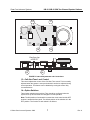
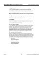
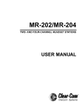
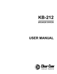
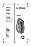
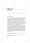
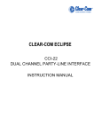
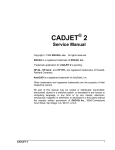
KB-211/KB-211GM
TWO-CHANNEL SPEAKER STATIONS
USER MANUAL
Clear-Com Intercom Systems
KB-211/KB-211GM Two-Channel Speaker Stations
Introduction
Congratulations and thank you for choosing this Clear-Com product.
The KB-211 and KB-211GM Two-Channel Speaker Stations are powerful,
user-friendly units that can serve as versatile intercom stations.
Please read this manual completely to better understand the functions of
these products. For questions not addressed in this manual, contact the
dealer or Clear-Com directly. Clear-Com applications support and service
people are ready to help.
Description
The Clear-Com PL-Pro™ KB-211 is a two-channel speaker station designed
for use in theatres, live performances, industrial environments, and small
television facilities. It features speech intelligibility, even in high noise levels,
and can be customized through its programmable options.
In addition, the Clear-Com PL-Pro™ KB-211GM also contains a jack for an
optional Clear-Com gooseneck panel microphone and a close-in, voiceoperated circuit (VOX). This circuit allows automatic, alternate dipping of the
panel microphone and the speaker in response to conversation.
Selectable, two-channel talking and/or listening allows the operator to
communicate on either of the intercom channels. The dual-action talk button
operates in electronic momentary or latching mode. Monitoring can be done
through the headset, the integral speaker, or both simultaneously. The KB-211
offers both visual and audible call signaling to attract the attention of
operators. The Remote Mic Kill (RMK) feature on main stations will turn off
any open microphones on the KB-211.
A balanced program input allows the monitoring of external audio using the
headset or speaker. This program input can also be used as a paging
function.
The KB-211 speaker station accepts dynamic headsets, such as the ClearCom PL-Pro™ Series HS-6 Telephone Handset or PT-4 Push-to-Talk Hand
Microphone. A sidetone control allows the operator to vary the level of his
voice heard through the headset and speaker.
The integral speaker can be turned on or off by a convenient front-panel
switch. An automatic speaker dipping circuit will lower the level of the speaker
whenever the talk button is activated. The KB-211GM’s close-in VOX dips the
speaker or gooseneck microphone automatically as the station is used. These
features help minimize acoustical feedback.
The KB-211 receives 30-VDC power from the Clear-Com intercom line. The
unit mounts either in a standard four-gang electrical outlet box or in an
optional Clear-Com V-Box. The extra-thick front panel and compact, surfacemount circuitry results in a reduced size and lighter weight package that
maintains Clear-Com ruggedness. The two intercom channels connect to a
© Clear-Com Intercom Systems 1999
1
Rev. A
KB-211/KB-211GM Two-Channel Speaker Stations
Clear-Com Intercom Systems
plug-on screw terminal strip. Male and female three-pin XLR connectors are
provided on the V-Box for an in-line connection to one of the intercom
channels.
The optional EB-TW daughter board module can be installed to provide an
interface to two intercom channels on a single microphone cable. Also, the
EB-4W 4-Wire daughter board module is available to allow long-distance
connections using separate pairs of wires for send audio and receive audio.
The EB-4W 4-Wire option supports two-channel operation.
The KB-211 and KB-211GM are compatible with all Clear-Com Party-Line
intercoms.
Quick Start
1.
Unpack the unit and inspect it for any damage that may have
occurred during shipping.
2.
Set the Option switches to the default (up) position.
3.
Connect the intercom lines. If only one intercom line is to be
connected, set Option Switch 1 to the ON or CLOSED position.
4.
Install the KB-211 into the four-gang outlet box or V-Box. (For
additional information, refer to the Clear-Com PL-Pro™ System
Installation Manual.)
5.
Set Listen Levels and Sidetones. (Refer to“5—Sidetone Control”
on page 4.)
6.
The speaker station should now be operating properly.
7.
Read the rest of this manual for further information.
Operation
Normal operation of the KB-211 Speaker Station only requires the front-panel
controls. The controls located elsewhere on the unit are intended to be setand-forget in nature. For intercom operation, set the Listen level control to the
desired level and press the Talk button when talking. If a headset or handset
is used, set the Sidetone control for each channel for the desired amount of
sidetone in the earphone. If the PT-4 hand-held, push-to-talk microphone is
used, or if the panel microphone is used on the KB-211GM, set the sidetone
controls for minimum feed-through to the speaker to prevent acoustic
feedback.
Front Panel
The controls, indicators, and connectors on the KB-211 and KB-211GM front
panels are shown on Figure 1 on page 3 and are described by the following
text.
Rev. A
2
© Clear-Com Intercom Systems 1999
Clear-Com Intercom Systems
11
KB-211/KB-211GM Two-Channel Speaker Stations
12
8
2
A
VOX
9
4
3
B
Channel Select
Panel Mic
Call
Intercom Level
Headset
Program Level
Off
Sidetone
On
Talk
PL
Speaker
pro
KB-211GM
Speaker
S tat ion
10
5
1
7
6
FIGURE 1: Front Panel
1—Talk Button and Lamp
The Talk button activates the microphone feed to the selected intercom
channel. The Talk button has a dual action (momentary or latching) depending
upon how the button is pressed. If desired, the latching function can be
defeated using an internal switch. The following describes the various
functions of this button.
•
Momentary—Press and hold the Talk button while speaking. Release it
when finished.
•
Latching—Press and release the button quickly to latch the Talk
function. Press and release the button again to turn off the Talk
function.
•
Talk Indication—The associated Talk lamp will illuminate green when
the Talk function is activated.
•
VOX indication—On the KB-211GM, when the VOX feature is enabled,
the Talk lamp will illuminate green when the Talk function is activated,
but will turn red when the panel microphone is in use. This
automatically dips the speaker volume.
© Clear-Com Intercom Systems 1999
3
Rev. A
KB-211/KB-211GM Two-Channel Speaker Stations
•
Clear-Com Intercom Systems
Speaker Dip—If the front-panel speaker is turned on and the VOX
feature is not used, pressing the Talk button will reduce the speaker
output level to avoid feedback.
2—Call Button and Lamp
Pressing the Call button will send a call signal on the selected channel. All the
call lights on that channel will then flash. Call signals can also be sent while
talking if required. The Call lamp will light while the Call button is pressed, or
whenever a call signal is present on the selected channel. An internal option
jumper can be set to allow the Call lamp to light when a call signal is present
on either channel.
3—Tone Alert
An audible tone alert can sound when a call signal is received on the selected
channel or either channel. This can be useful when the operator’s attention
has been drawn away from the KB-211 indicator panel. The audible tone alert
level can be adjusted or turned off by an internal control. The Tone Alert will
not sound if a call signal is originated at the KB-211 station or if the Speaker
ON/OFF Switch is turned off. The Tone Alert plays through both the speaker
and headset if the Speaker ON/OFF Switch is turned on.
4—Intercom Level Control
Turn this control to set the listen level required on the speaker or headset.
This control does not affect the Tone Alert level or the Program Input level.
5—Sidetone Control
Sidetone is the level of the operator’s voice that is heard while talking on the
intercom. Setting a comfortable level of sidetone will ensure that the intercom
line sounds alive and also helps modulate the operator’s voice relative to
other voices on the line.
Typically, different Sidetone settings are needed depending upon whether the
speaker is used. Use one of the following procedures to correctly set the
Sidetone level control.
Sidetone Adjustment Procedure for Headset
Follow these steps to adjust a headset’s sidetone level.
1.
Set the Intercom Level control to a comfortable level by having
someone talk to the operator from another station.
2.
Press the Talk button and speak into the microphone while
turning the Sidetone control slowly back and forth until the voice
reaches a comfortable level in the headset.
Follow these steps to adjust the sidetone for gooseneck microphones on the
KB-211GM or PT-4 hand-held, push-to-talk microphone with the Speaker
turned on.
Rev. A
4
© Clear-Com Intercom Systems 1999
Clear-Com Intercom Systems
KB-211/KB-211GM Two-Channel Speaker Stations
1.
Set the VOX control fully counterclockwise to disable this feature.
(KB-211GM only)
2.
Set the Intercom Level control to a comfortable level.
3.
Press the Talk button and speak into the microphone while
turning the Sidetone control slowly back and forth. There should
be a point where the operator’s voice (and any accompanying
acoustic feedback) disappears. This is the null point.
4.
Readjust the VOX control. (Refer to “12—VOX Control (KB211GM only)” on page 6.)
6—Program Level Control
Adjust the Program Level control to set the program audio level heard in the
headset or panel speaker.
Note: Forcing the trimpots past their stop points will damage them.
7—Speaker ON/OFF Switch
The Speaker ON/OFF Switch turns the front-panel speaker on or off. This
switch also controls whether the Tone Alert is heard through the speaker. The
speaker volume will automatically dip when the talk function is set, unless the
VOX function is enabled.
8—Mic Select Switch (KB-211GM only)
The Mic Select switch selects whether the panel microphone or the headset
microphone is active. When the VOX feature is enabled, it is only operational
when the panel microphone is active.
9—Channel Switch
This switch selects the intercom channel (A or B) on which the speaker station
is active.
10—Headset Connector
The headset connector is located on the front panel. All Clear-Com headsets
are recommended for use with the KB-211. The Clear-Com PT-4 Push-to-Talk
Microphone or the HS-6 Telephone Handset will also plug into the headset
connector. The following is a description of the characteristics of a suitable
headset:
•
Mic Type—Dynamic; 150 to 400 ohms impedance; -55 dB output level
•
Headphone—Dynamic; 50 to 2000 ohms impedance.
The wiring of the headset is to be as follows:
•
Pin 1—microphone ground (shield)
•
Pin 2—microphone hot
•
Pin 3—headphone ground
© Clear-Com Intercom Systems 1999
5
Rev. A
KB-211/KB-211GM Two-Channel Speaker Stations
•
Clear-Com Intercom Systems
Pin 4—headphone hot.
The microphone and headphone wiring in the headset cord must be
individually shielded.
Note: Do not connect Pins 1 and 3 together. Headset extension cords or
headset ”Y” cables are not recommended because they may increase
crosstalk between channels.
11—Panel Mic Connector (KB-211GM only)
Clear-Com recommends the GM-9 (9 in. long) and GM-18 (18 in. long) plug-in
panel microphones be used with the KB-211GM. Both are the electret type.
The 1/4-in. phone jack on the microphone mates with the Panel Mic
receptacle on the KB-211GM’s front panel.
To install a GM-9 or GM-18 microphone:
1.
Remove the plastic plug from the jack, if present.
2.
If a set screw is present in the microphone-mounting flange,
check and unscrew it to make sure it is clear of the threads in the
bushing.
3.
Screw the microphone into the bushing and tighten.
4.
Optional: Replace the set screw supplied with the gooseneck
microphone on top of the microphone-mounting flange and turn it
clockwise to lock the microphone in place.
12—VOX Control (KB-211GM only)
When the panel microphone is selected on the KB-211GM, the VOX control
should be adjusted for proper operation. This control is located to the right of
the panel microphone connector and is recessed slightly into the front panel.
Use a narrow, flat-blade screwdriver such as a "greenie" or "tweaker" for this
adjustment. When the adjustment is correctly set, the Talk lamp will be red
when speaking into the panel microphone and will be green when hearing
audio from the speaker. Turning the control clockwise makes the KB-211GM
more sensitive. The VOX feature can be disabled by turning the VOX control
fully counterclockwise.
Internal Adjustments and Connections
The controls and connectors inside the KB-211 are shown in the following
figure and described by the following text. The controls can be accessed
without completely removing the panel from its wall box or V-Box enclosure
by removing the top two screws and loosening the bottom two screws a few
turns. The panel can then be leaned out from the wall to make the controls
accessible as shown in the lower view of Figure 2 on page 7.
Rev. A
6
© Clear-Com Intercom Systems 1999
Clear-Com Intercom Systems
KB-211/KB-211GM Two-Channel Speaker Stations
18
P2 Must be
installed if
no option
17
P3 Must be
installed if
no option
P1 Call
on Both
P1 Call on
Selected
15
16
View from top
of KB-211
1 2 3
Front Panel
13
14
FIGURE 2: Internal Adjustments and Connections
13—Call Alert Tone Level Control
This control adjusts the volume of the Call Alert Tone sound. This is normally
adjusted when the system is set up and shouldn’t need to be adjusted during
normal operation. This feature can be disabled by turning the control fully
counterclockwise.
14—Option Switches
Three Option switches are provided. They should be configured when the
system is set up and shouldn’t be changed in normal operation.
Note: The ON position of each switch is toward the circuit board and the OFF
position is toward the front panel. The default position of the switches is in the
OFF position. The function of each switch is as follows:
© Clear-Com Intercom Systems 1999
7
Rev. A
KB-211/KB-211GM Two-Channel Speaker Stations
Clear-Com Intercom Systems
1—Single Channel
In some installations, the KB-211 is intended to be used only with one
intercom channel. Setting the Single Channel switch to the ON position will
connect the KB-211 to the one intercom channel regardless of the position of
the front-panel Channel selector.
Note: In two-channel installations, this switch must be set to the OFF position.
2—Long Line
If a long cable run is unavoidable and approaches 700 ft. or more, set the
Long Line option switch to the ON position. The ability to set an effective
sidetone depends upon properly setting this switch.
3—Latch Diable
Setting the Latch Disable switch to the ON position will disable the latching
function of the Talk button. In this mode, the Talk button must be held in
continuously while the operator is talking.
15—Call Signal Jumper
In some installations it is important to receive a call signal from either channel,
regardless of the setting of the Channel selector. The plug-on jumper P1
makes the Call lamp respond to either the selected channel or to both
channels, depending upon its orientation. By default, the jumper is set to the
selected channel position. When the TW or 4-Wire Option modules are
installed, this jumper is not used. In TW operation, the call signal always
originates on channel A. In 4-Wire operation, the call signal is not used.
16—Intercom Line Connection
The KB-211 contains a five-terminal, plug-on connector for intercom line
connection. This connector is intended to be unplugged from the circuit board
when connecting the intercom line, and then plugged back on when the wiring
is completed. The connections for each pin are visible on the circuit board
when the connector is unplugged. The pinout of this connector is as follows:
Rev. A
•
Pin 1—(NC)
•
Pin 2—Channel A Audio
•
Pin 3—Channel B Audio
•
Pin 4—Power (+30 VDC)
•
Pin 5—Ground (Shield).
8
© Clear-Com Intercom Systems 1999
Clear-Com Intercom Systems
KB-211/KB-211GM Two-Channel Speaker Stations
Pin 1
2
3
Channel A
1
XLR
Connector
KB-211 Intercom
Connector
FIGURE 3: One-Channel Cable Wiring
2
Pin 1
3
Channel A
3
Channel B
1
2
1
KB-211 Intercom
Connector
XLR
Connectors
FIGURE 4: Two-Channel Cable Wiring
17—Program Input
A three-terminal, plug-on connector provides the program input to the station.
Program is fed to the headset and speaker. The level to the speaker or
headset is controlled by the Program Level control. The Program Input
accepts a balanced or unbalanced line-level audio signal from -20 dBv to +10
dBv. If this input is connected to the stage announce (SA) output of a Main
Station it can be used as a paging input. Since the level of this input is
independently adjustable from the intercom audio volume, it can be used to
override the intercom audio. The pinout of this connector is as follows:
•
Pin 1— Ground (Shield)
•
Pin 2— + Signal
•
Pin 3— - Signal.
© Clear-Com Intercom Systems 1999
9
Rev. A
KB-211/KB-211GM Two-Channel Speaker Stations
Clear-Com Intercom Systems
Program Input
Cable Wiring:
Pin 1
2
3
1
KB-211 Program
Input Connector
XLR
Connector
FIGURE 5: Program-Input Cable Wiring
18—Option Board Jumpers
The three jumper plugs P1, P2, and P3 must be installed when optional
modules are not used. When the optional EB-4W or EB-TW modules are
used, both P1 and P3 must be removed. In the KB-211GM, P2 is replaced by
the VOX module. Save these jumper plugs for possible future use.
Note: The KB-211 will not operate without either these jumper plugs or the
optional modules installed.
Rev. A
10
© Clear-Com Intercom Systems 1999
Clear-Com Intercom Systems
KB-211/KB-211GM Two-Channel Speaker Stations
EQ/
LIM
Sidetone
Null
Intercom
Volume
Headset
Mic
Speaker Speaker
On/Off
Speaker
Dip
Mic
Mute
Long Line
Headset
Output
Talk
Talk
Program
Mute
Call Alert
Tone Level
Microprocessor
Call
Latch
Disable
Program
Level
Call
Light
Single
Chan.
Call Send &
Receive
Power
RMK
Channel
Switch
TW Option
Balanced
Program
Input
Common
+30 VDC
Ch. B
Ch. A
Ground
Ch. B
4-Wire
Input
16 VAC
Rectifier
Ch. A
Power
2-Wire / 4-Wire
Select
Ch. B
4-Wire
Output
4-Wire
Option
Ch. A
FIGURE 6: KB-211 Block Diagram
© Clear-Com Intercom Systems 1999
11
Rev. A
KB-211/KB-211GM Two-Channel Speaker Stations
Headset
Mic
EQ/
LIM
Clear-Com Intercom Systems
Sidetone
Null
Intercom
Volume
Mic Select
Speaker Speaker
On/Off
Speaker
Dip
Panel
Mic
Mic Dip /
Mute
Long Line
Headset
Output
VOX
Talk/
VOX
Talk
Program
Mute
Red /
Green
Call Alert
Tone Level
Microprocessor
Call
Latch
Disable
Program
Level
Call
Light
Single
Chan.
Call Send &
Receive
Power
RMK
Common
+30 VDC
Ch. B
Ch. A
Ground
Channel
Switch
TW Option
Balanced
Program
Input
Ch. B
4-Wire
Input
16 VAC
Rectifier
Power
Ch. A
2-Wire / 4-Wire
Select
Ch. B
4-Wire
Output
4-Wire
Option
Ch. A
FIGURE 7: KB-211GM Block Diagram
Troubleshooting
•
System does not operate. Talk Light does not come on when Talk
button is pressed.
Scenario 1
The KB-211 doesn’t have an intercom connection. If the EB-4W 4-Wire Option
Module is connected, the KB-211 may not be receiving AC power.
Solution: Check connections and cable.
Rev. A
12
© Clear-Com Intercom Systems 1999
Clear-Com Intercom Systems
KB-211/KB-211GM Two-Channel Speaker Stations
Scenario 2
The KB-211 has an internal failure.
Solution: Unit requires servicing.
•
Speaker does not operate, but the Talk Light comes on when Talk
button is pressed.
Scenario 1
The Speaker switch is turned off, the volume knob is turned all the way down,
or the channel switch is set to the unused channel.
Solution: Adjust controls appropriately.
Scenario 2
The speaker plug or wiring has come loose.
Solution 2: Make sure speaker is connected internally.
Scenario 3
Plug P3 is missing on circuit board.
Solution: Plug P3 must be installed in J3 jack if the EB-TW or EB-4W options
are not used.
•
Hum or buzz in the system.
Scenario 1
Inductive pickup caused by close proximity of this speaker station or
connected stations to power lines or transformers.
Solution: Relocate the offending unit or wiring. If the cable run is exceptionally
long, consider adding and using the EB-4W 4-Wire Option Module. (Requires
an additional 4-wire interface at the opposite end of the “long run.”)
•
System feedback (Acoustical).
Scenario 1
Intercom Level control at this station or another station is set too high.
Solution: Adjust.
Scenario 2
The Sidetone control at this station or another station is not correctly adjusted.
Solution: Adjust. Refer to “5—Sidetone Control” on page 4.
Scenario 3
Channel not terminated.
Solution: Set the Main Station or Power Supply termination switch for that
channel to the ON position.
Scenario 4
The Channel switch set to an unconnected channel.
© Clear-Com Intercom Systems 1999
13
Rev. A
KB-211/KB-211GM Two-Channel Speaker Stations
Clear-Com Intercom Systems
Solution: If only one intercom line is connected, set Option Switch 1 to the ON
or CLOSED position to link both channel switch positions to the same
intercom line.
Scenario 5
A headset extension cord was used.
Solution: Headset extension cords are not recommended.
•
VOX problems (KB-211GM only)
Scenario 1
VOX stays tripped (red light on) or the sensitivity is set too high.
Solution: Turn VOX sensitivity control in a counter-clockwise direction.
Scenario 2
VOX will not trip with voice (green light on) or the sensitivity is set too low.
Solution: Turn VOX sensitivity control in a clockwise direction.
Note: VOX is intended for close-in operation.
•
Excessive crosstalk
Scenario 1
High DC resistance has a ground return.
Solution: Use heavier cable to add additional conductor(s) to the ground
return. If the cable run is exceptionally long, consider adding and using the
EB-4W 4-Wire Option Module.
Scenario 2
The multi-channel cable pairs are not individually shielded.
Solution: Replace the cable with individually shielded pairs.
Scenario 3
Headset cables are not wired or shielded properly.
Solution: Correct the wiring and use headsets with properly shielded wiring
(see “10—Headset Connector” on page 5).
•
Program signal sounds distorted.
Scenario 1
The Program Level control is set too high.
Solution: Turn the Program Level control counter-clockwise.
Scenario 2
Overload of Program Input circuit.
Solution: Reduce the gain of the program signal at the source, such as an
audio mixer.
Rev. A
14
© Clear-Com Intercom Systems 1999
Clear-Com Intercom Systems
•
KB-211/KB-211GM Two-Channel Speaker Stations
The call signal does not function.
Scenario 1
Excessive DC loading of intercom line.
Solution: Remove any audio transformers or other equipment that may be
connected across the intercom line. If equipment other than Clear-Com
intercom equipment must be connected to the intercom line, please contact
Clear-Com application or service personnel for information or
recommendations.
Scenario 2
Far too many terminations on the intercom line.
Solution: Check all main stations and power supplies to make sure each
intercom channel is terminated at only one point.
Scenario 3
Plug P1 is missing on circuit board.
Solution: Plug P1 must be installed in the J1 jack if the EB-4W or EB-TW
options are not used.
© Clear-Com Intercom Systems 1999
15
Rev. A
KB-211/KB-211GM Two-Channel Speaker Stations
Clear-Com Intercom Systems
Parts Lists
Parts List for the KB-211 / KB-211GM Main PCB and Chassis
Capacitors
Value
220
.01
22
4.7
4.7
.047
100
22
47
220
470
.0022
.0047
.01
uF
uF
uF
uF
uF
uF
uF
pF
pF
pF
pF
uF
uF
uF
Type
Aluminum
Ceramic Disc
Tantalum
Tantalum
Aluminum NP
Mylar
Aluminum
Ceramic Disc SMD
Ceramic Disc SMD
Ceramic Disc SMD
Ceramic Disc SMD
Ceramic Disc SMD
Ceramic Disc SMD
Ceramic Disc SMD
Voltage
35V
1.4KV
16V
35V
50V
100V
35V
50V
50V
50V
50V
50V
50V
50V
Tol.
5%
5%
5%
5%
10%
10%
10%
Part #
150021
150029
150032
150044
150087
150131
150136
151116
151120
151128
151132
151152
151156
151160
.047
.1
uF
uF
Ceramic Disc SMD
Ceramic Disc SMD
50V
50V
10%
10%
151168
151172
.22
.47
1
10
uF
uF
uF
uF
Ceramic Disc SMD
Tantalum SMD
Tantalum SMD
Tantalum SMD
50V
35V
16V
25V
10%
10%
10%
10%
151176
151184
151185
151192
Designator
C8 C47
C1
C28
C6
C11
C24
C17 C41
C14
C5 C19 C27 C30
C26
C7 C46
C16
C9 C20 C22
C13 C37 C38 C40C31
C29
C18 C35
C10 C25 C32 C33 C34
C36 C45
C15 C21 C23
C44 C39
C2 C4 C12 C43
C42
Part #
410002
410005
410075
411181
411254
411293
411326
411339
411354
411381
411389
411406
411418
411431
411465
411469
Designator
R15 R53
R46
R44
R27
R25
R45 R35
R13
R47 R51
R20
R22
R14 R33
R43
R18 R21 R42
R48
R28
R17
20%
5%
Resistors
Value
10
390
1.3K
2.2
39.2
100
221
301
432
825
1.00K
1.50K
2.00K
2.74K
6.19K
6.81K
Rev. A
OHM
OHM
OHM
OHM
OHM
OHM
OHM
OHM
OHM
OHM
OHM
OHM
OHM
OHM
OHM
OHM
Power
1/4
1/4
1/2
1/10
1/10
1/10
1/10
1/10
1/10
1/10
1/10
1/10
1/10
1/10
1/10
1/10
Type
Carbon Film
Carbon Film
Carbon Film
SMD
SMD
SMD
SMD
SMD
SMD
SMD
SMD
SMD
SMD
SMD
SMD
SMD
Tol.
5%
5%
5%
5%
1%
1%
1%
1%
1%
1%
1%
1%
1%
1%
1%
1%
16
© Clear-Com Intercom Systems 1999
Clear-Com Intercom Systems
8.25K
12.1K
15.0K
20.0K
56.2K
100K
121K
475K
1.0M
10K
47K
100K
220K
470K
Pot
Pot
Pot
OHM
OHM
OHM
OHM
OHM
OHM
OHM
OHM
OHM
OHM
OHM
OHM
OHM
OHM
10K
5K
5K
1/10
1/10
1/10
1/10
1/10
1/10
1/10
1/10
1/10
KB-211/KB-211GM Two-Channel Speaker Stations
SMD
SMD
SMD
SMD
SMD
SMD
SMD
SMD
SMD
X4 SMD DIP Isolated
X4 SMD DIP Isolated
X4 SMD DIP Isolated
X4 SMD DIP Isolated
X4 SMD DIP Isolated
TRIMPOT
TRIMPOT
POT
1%
1%
1%
1%
1%
1%
1%
1%
5%
1%
1%
1%
1%
1%
411477
411493
411502
411514
411557
411581
411589
411646
411677
416016
416018
416019
416020
416021
470058
470063
470081
R52
R19 R38
R16
R24 R30 R31 R34 R39
R37 R41
R6 R12 R49 R50
R32
R26
R54
R8 R9 R10 R11
R2 R3
R1
R7
R4
R36
R40 R23
R29
Device
LED
LED
IC
IC
Diode
IC
Transistor
Diode
Description
BI-COLOR RED/GREEN 3 LEAD
LED, YELLOW, ULTRA BRIGHT T1 3/4
LM384 POWER 4W OP AMP 14 PIN
7805L POS 5V REGULATOR TO-92 PKG
BAV70 DUAL DIODE COM CATHODE SMD
833 DUAL OPAMP... SMD
2907A PNP 60V 600MA... SMD
BAV99 DUAL DIODE... SMD
Part #
390032
390057
480012
480088
481019
481023
481027
481033
Transistor
IC
Transistor
Diode
Transistor
IC
MPSA14 DNPN 30V 300MA... SMD
DG444 QUAD CMOS ANALOG SW SMD
J175 P-CHANNEL JFET... SMD
5.1V 5% ZENER 1/4W... SMD
MPSA64 DPNP 30V 500MA SMD
MICROPROCESSOR, KB/MR SERIES
481038
481050
481056
481061
481075
710508
Designator
D8
D14
IC5
IC11
D9 D12 D15 D16
IC1 IC2 IC8
Q2
D1 D2 D3 D4 D5 D6
D11 D13
Q5
IC9
Q1 Q3
D7 D10
Q4
IC10
Diodes and Transistors
Miscellaneous
Device
Connector
XLR
Connector
Pot
Pot
Pot
Button
Button
Lens
Speaker
Description
5 POS, SCREW TERM. PLUG-IN 5MM
4 PIN M FLUSH MOUNT W/SOLDER CUPS
3 POS, SCREW TERM. PLUG-IN 5MM
SHAFT FOR PIHER POT, GREY
PIHER TRIMPOT SHAFT, GREY
KNOB GREY INSERT .45 DIA POINT TO RD
ROUND MINIATURE BUTTON, BLACK
RECT. MINIATURE BUTTON, BLACK
LENS, YELLOW, ROUND FOR T1 3/4
2 1/2 IN. SPKR 16 OHM 3.5W
© Clear-Com Intercom Systems 1999
17
Part #
210085
210286
210370
240043
240057
240077
240081
240082
240099
500139
Designator
P4
P10
R36
R23 R40
R29
S5
S4
D14
Rev. A
KB-211/KB-211GM Two-Channel Speaker Stations
Switch
Switch
Switch
Switch
Wire
DPDT P.B. MINIATURE W/LONG PLUNGER
DPDT ROCKER PC MOUNT W/BRACKET
DIP SWITCH PIANO 3 POS
SPDT ROCKER, PC MNT W/BRACKET
4 CONNDUCTOR FLAT CABLE
Clear-Com Intercom Systems
510107
510111
510114
510125
770017
S4 S5
S2
S3
S1
W1
Part #
150002
150014
150030
150035
150061
150082
150109
150146
150158
Designator
C13
C10
C8 C12
C1 C2 C3
C5
C4
C6 C9
C11
C14
Part #
410013
410036
410055
410058
410148
410151
415003
415014
470038
Designator
R1 R12 R16 R17 R13
R2
R6
R4 R8
R11 R15
R14
R3 R10
R9
R5
Part #
480000
480006
480010
480038
480162
Designator
D3 D4 D5 D6 D7 D8
Q1 Q2
IC1 IC2
D1 D2
D9
Part #
210050
240069
510126
Designator
Parts List for the KB-211GM VOX PCB
Capacitors
Value
1
470
4.7
.1
680
.022
.01
220
22
uF
pF
uF
uF
pF
uF
uF
uF
uF
Type
Aluminum NP
Ceramic Disc
Tantalum
Monolithic
Ceramic Disc
Monolithic
Monolithic
Aluminum
Tantalum
Voltage
50V
50V
16V
50V
50V
50V
50V
16V
10V
Tol.
10%
10%
10%
10%
10%
20%
20%
10%
Resistors
Value
4.7K
6.8K
1.5K
1M
100K
20K
10K
100K
Pot
Power
1/4
1/4
1/4
1/4
1/4
1/4
OHM
OHM
OHM
OHM
OHM
OHM
OHM
OHM
50K
Type
Carbon Film
Carbon Film
Carbon Film
Carbon Film
Metal Film
Carbon Film
X5 SIP ISOLATED
X4 SIP ISOLATED
TRIMPOT
Tol.
5%
5%
5%
5%
1%
5%
Diodes and Transistors
Device
Diode
Transistor
IC
Diode
Diode
Description
1N4148 SIGNAL 10MA 75PIV
PN2222A NPN 30V
LF353 BIFET OP AMP
1N5231B ZENER 5.1V .5W 5%
1N4740A ZENER 10V 0.5W 5%
Miscellaneous
Device
Panel Mic Jack
Pot
Switch
Rev. A
Description
PHONE JACK
SHAFT FOR PIHER POT BLACK
DPDT TOGGLE, PC MNT W/BRACKET
18
R5
S1
© Clear-Com Intercom Systems 1999
Clear-Com Intercom Systems
KB-211/KB-211GM Two-Channel Speaker Stations
FIGURE 8: Main PCB Component Layout
© Clear-Com Intercom Systems 1999
19
Rev. A
KB-211/KB-211GM Two-Channel Speaker Stations
Clear-Com Intercom Systems
This page is a place holder.
Rev. A
20
© Clear-Com Intercom Systems 1999
FIGURE 9: KB-211 Schematic
© Clear-Com Intercom Systems 1999
21
Rev. A
KB-211/KB-211GM Two-Channel Speaker Stations
Clear-Com Intercom Systems
This page is a place holder.
Rev. A
22
© Clear-Com Intercom Systems 1999
Clear-Com Intercom Systems
KB-211/KB-211GM Two-Channel Speaker Stations
FIGURE 10: VOX PCB Component Layout
© Clear-Com Intercom Systems 1999
23
Rev. A
KB-211/KB-211GM Two-Channel Speaker Stations
Clear-Com Intercom Systems
FIGURE 11: VOX Schematic
Rev. A
24
© Clear-Com Intercom Systems 1999
Clear-Com Intercom Systems
KB-211/KB-211GM Two-Channel Speaker Stations
Technical Specifications
Headset Microphone Pre-Amp
Input Type:
Impedance:
Input Level:
Gain from headset
mic to intercom line:
Dynamic
1k ohm
-55 dBV nominal; -10 dBV max.
+41 dB
Panel Microphone Pre-Amp (KB-211GM only)
Input Type:
Input Level:
Gain from panel
mic to intercom line:
Electret
-45 dBV nominal
+31 dB VOX not tripped/+41 dB VOX tripped
Pre-Amp Response Curve
Frequency Response:
Limiter Range
250 Hz to 12 kHz, contoured for intelligibility
20 dB
Headphone Amplifier
Load Impedance Range:
Output Level:
Distortion:
Frequency Response:
Gain from intercom line:
Power Output:
50 ohm to 2k ohm
at least +20 dBV across 600 ohm
< 0.5% THD at 1 kHz
200 Hz to 15 kHz, ±3 dB
+37 dB
110 dB SPL
Speaker Amplifier
Speaker Type:
Power Output:
Frequency Response:
Signal-to-Noise:
Gain from intercom line:
Distortion:
Speaker Level:
2.5 in. round, 16 ohm
2 W into 16 ohms
200 Hz to 15 kHz, ±3 dB
75 dB
+37 dB
< 0.5% THD at 1 kHz
98 dB SPL at 3 ft.
Program Amplifier
(Transformerless, balanced differential input)
Input Level:
-20 dBV
Input Impedance:
> 100k ohm
Frequency Response:
150 Hz to 15 kHz, ± 3 dB
© Clear-Com Intercom Systems 1999
25
Rev. A
KB-211/KB-211GM Two-Channel Speaker Stations
Clear-Com Intercom Systems
Power Requirements
Voltage:
Current:
30-VDC standard unit;
16 to 18 VAC with 4-Wire Option Module
100 mA average
Internal Connectors
Intercom:
Program:
AC Power
(4-Wire Option Module):
five-position, plug-on screw terminals
three-position, plug-on screw terminals
two-position, plug-on screw terminals
Internal Controls
(1) Call Signal jumper; (3) Option switches; (1) Tone Alert Volume control
Front Panel Connectors
Panel Mic:
Headset:
(1) 1/4-in. panel mounting jack (KB-211GM only)
(1) XLR-4M
Front Panel Controls & Indicators
(1) Panel/Headset Mic switch (KB-211GM only); (1) Program Level control; (1) Intercom
volume control; (1) Sidetone control; (1) Talk button; (1) Call button; (1) VOX control (KB211GM only); (1) Channel selector; (1) Speaker On-Off switch; (1) Talk LED; (1) Call LED
Environmental
32 to 122 F (0 to 50 C)
Dimensions
8.25 in. W x 4.5 in. H x 1.75 in. D (210 mm x 114 mm x 44 mm)
Weight
1.22 lbs. (0.56 kg)
Notice About Specifications
While Clear-Com makes every attempt to maintain the accuracy of the information
contained in its product manuals, that information is subject to change without notice.
Performance specifications included in this manual are design-center specifications and
are included for customer guidance and to facilitate system installation. Actual operating
performance may vary.
KB-211/KB-211GM Manual P/N 810253
(C) 1999 Clear-Com Systems
All Rights Reserved
Rev. A
26
© Clear-Com Intercom Systems 1999
Clear-Com Intercom Systems
KB-211/KB-211GM Two-Channel Speaker Stations
Clear-Com Limited Warranty
The Clear-Com warranty does not cover any defect, malfunction, or failure
caused beyond the control of Clear-Com, including unreasonable or negligent
operation, abuse, accident, failure to follow instructions in the manual,
defective or improper associated equipment, attempts at modification and
repair not authorized by Clear-Com, and shipping damage. Products with
their serial numbers removed or defaced are not covered by this warranty.
This warranty is the sole and exclusive express warranty given with respect to
Clear-Com products. It is the responsibility of the user to determine before
purchase that this product is suitable for the user's intended purpose.
Any and all implied warranties, including the implied warranty of
merchantability are limited to the duration of this express limited warranty.
Neither Clear-Com nor the dealer who sells Clear-Com products is liable for
incidental or consequential damages of any kind.
For your own records fill in the information below:
Model No
Serial No.
Date Purchased
Purchased from (dealer)
Address
City
State
ZIP
Factory Service
All equipment returned for repair must be accompanied by documentation
stating the return address, telephone number, date of purchase, and a
description of the problem.
Note: Do not return any equipment to the factory without first obtaining a
Return Authorization Number.
Send equipment to be repaired to:
Customer Service Department
Clear-Com Intercom Systems
4065 Hollis Street
Emeryville, CA 94608-3505
Telephone: (510) 496-6666
Fax: (510) 496-6601
Warranty Repairs
If in warranty, no charge will be made for the repairs. Equipment being
returned for warranty repair must be sent prepaid and will be returned
prepaid.
© Clear-Com Intercom Systems 1999
27
Rev. A
KB-211/KB-211GM Two-Channel Speaker Stations
Clear-Com Intercom Systems
Non-Warranty Repair
Equipment that is not under warranty must be sent prepaid to Clear-Com. If
requested, an estimate of repair costs will be issued prior to service. Once
repair is approved and repair of equipment is completed, the equipment will
be shipped freight collect from the factory.
Rev. A
28
© Clear-Com Intercom Systems 1999
4065 Hollis Street, Emeryville, CA 94608
(510) 496-6666 Fax (510) 496-6601
Manual Part Number 810253 Rev. A