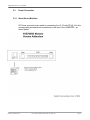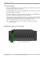
1
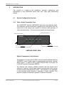
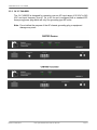
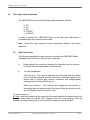
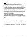
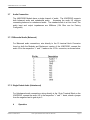
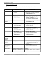
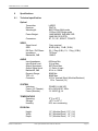
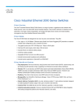
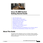
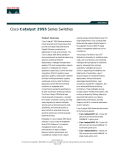
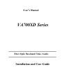
User’s Manual
VA700XD Series
Fiber Optic Baseband Video /Audio
Installation and User Guide
VAB700XD Series User’s Manual
Revision 1.0 MAY 2004
VAB700XD Series Users and Installation Manual
Radiant Communications makes every effort to ensure that this document is accurate.
However, because we are always improving our products, we are unable to guarantee the
accuracy of the contents of this document after the date of publication and we disclaim liability
for any changes, error or omissions.
Copyright
Copyright @ 2004 by Radiant Communications. Printed in the United States of America. No
part of this publication may be reproduced, stored in a retrieval system, or transmitted, in any
form or by any means, electronic, mechanical, photocopying, recording, or otherwise, without
written permission of the publisher.
All rights reserved, VAB700XD Series User’s Manual
Limitation of Liability
In no event shall Radiant Communications be liable for any defect in hardware or software or
loss or inadequacy of data of any kind, or for any direct, indirect, incidental, or consequential
damages in connection with or arising out of the performance or use of any product furnished
hereunder. Radiant Communication’s responsibility shall in no event exceed the purchase
price of the product purchase hereunder. The foregoing limitation of liability shall be equally
applicable to any service provide by Radiant Communications or its authorized agent.
Radiant Communications
Fiber Optic Baseband Video/Audio One Direction
Page 2
VAB700XD Series User’s Manual
TABLE OF CONTENTS
1
SAFETY INSTRUCTIONS
2
INTRODUCTION
2.1
2.1.1
2.1.2
2.1.3
2.2
2.2.1
2.3
3
INSTALLATION
3.1
3.2
3.3
3.3.1
3.3.2
3.4
3.5
3.6
3.7
3.7.1
3.7.2
4
System Configuration
Video/Audio Transmitter
Video/Audio Receiver Front View
Video/Audio Receiver Rear View
Equipment Description
Base Model Descriptions
Example Applications
Unpacking The Unit
General Installation
Power Connection
Receiver
Transmitter
Fiber Optic Cables Connection
Fiber Optic Ports
Video Cables
Audio Connections
Differential (Balanced)
Singled Ended (Unbalanced)
OPERATION
4.1
Radiant Communications
Turn On Procedure
Fiber Optic Baseband Video/Audio One Direction
Page 3
VAB700XD Series User’s Manual
TABLE OF CONTENTS
5
MAINTENANCE and TROUBLESHOOTING
5.1
5.2
6
SPECIFICATIONS
6.1
7
Maintenance
Troubleshooting
Technical specifications
CUSTOMER SUPPORT
7.1
7.2
7.3
Radiant Communications
Return Policy
Advance Replacement Policy
Warranty Policy
Fiber Optic Baseband Video/Audio One Direction
Page 4
VAB700XD Series User’s Manual
1
SAFETY INSTRUCTIONS
THE VAB700XD SYSTEM MAY CONTAIN A CLASS IIIb LASER.
PLEASE OBSERVE THE FOLLOWING SAFETY PRECAUTIONS THAT
APPLY TO LASER EQUIPT UNITS.
WARNING: Do not disconnect the fiber optic external connector with the
power turned on. Exposure to Class IIIb Laser radiation is possible when
the external fiber connector is disconnected while the unit is still powered
up. Ensure the rubber boot is in place whenever the fiber optic cable is
disconnected.
CAUTION: Attempting to make adjustments or performing operations
other than those specified may result in hazardous radiation exposure.
Exposure for only seconds can cause permanent eye damage as well as
other injuries.
Radiant Communications
Fiber Optic Baseband Video/Audio One Direction
Page 5
VAB700XD Series User’s Manual
2
INTRODUCTION
This manual is a guide to the installation, operation, applications and
maintenance of the VAB700XD series fiber optic video optic transmission
system.
2.1
System Configuration Overview
2.1.1 Video / Audio Transmitter Front
The VAB700XDT and the VAB700XDR share the same indicator panel.
The indicators provide information regarding the local optical link, the
optical link at the remote end (relative to observer) and presence of
video and data activity. The front and rear panels are shown below:
Data Present Indicator
Video Present Indicator
DV100
PWR
VIDEO
DATA
LLINK
RLINK
Power Indicator
Local Link:
Local Optical Receiver is synchronized
Remote Link:
Remote Optical Receiver is synchronized
VAB700XD FRONT VIEW
Optical Transmission Link Indictors:
The presence of Local Link (LLINK) on the front panel indicates that the
INCOMING optical digital signal is synchronized and being received
without errors. In order for ANY OTHER INDICATORS to be valid, the
LLINK LED must be illuminated GREEN.
The Remote Link Indicator (RLINK) indicates that the remote end’s
(relative to observer) optical digital signal is synchronized at the remote
end and is being received without errors. This indicator is not applicable
to this particular model because it operates in single direction. This
indicator requires bi-directional operation to become functional.
Radiant Communications
Fiber Optic Baseband Video/Audio One Direction
Page 6
VAB700XD Series User’s Manual
2.1.2 Video / Audio Rear View
The VAB700XDT and the VAB700XDR also have the same (Modular)
rear panel, with the exception of the VAB700XDT provides a Video Input
BNC and the VAB700XDR provides a Video Output BNC. The Modular
rear panel is depicted below.
Note: Most newer models provide a 10 pin terminal block.
Fiber Optic Port
12 VDC Power Connector
Data Connector
Audio Connector
Video Connector
VAB700XD REAR VIEW
2.2
Equipment Description
The system is capable of transmitting and receiving 1 simplex video signal and 1
duplex audio channel over 1 optical fiber.
Depending on the distance requirements between sites, the VAB700XD Series may
be equipped to operate over multi-mode fiber or over single mode fiber. Distances
between the transmitter and receiver can be up to 10 Km for multi-mode operation
and up to 110 Km for singlemode operation.
The VAB700XD system employs uncompressed analog to digital modulation
techniques, which provides for superior receiver output stability and is unaffected by
changes in the fiber path attenuation caused by environmental factors, splicing or
aging.
The VAB700XDT accepts the baseband video signal for transmission via an optical
digital carrier over a single optical fiber. At the distant end, the VAB700XDR receiver
accepts the optical carrier and converts it to the output video channels.
Radiant Communications
Fiber Optic Baseband Video/Audio One Direction
Page 7
VAB700XD Series User’s Manual
2.2.1 VAB700XD SERIES BASE MODELS
The VAB700XD Series always includes simplex video. The following table describes
the base model Options:
Tx Model
Rx Model
Description
VA700MD-R-XYZ
VA700MDL-R-XYZ
VAB700SD-R-XYZ
MM 14DB 850NM
MM 12DB 1300NM
SM 14DB 1310NM
CCTV Versions:
VA700MD-T-XYZ
VA700MDL-T-XYZ
VA700SD-T-XYZ
Broadcast Versions:
VAB700MD-T-XYZ
VAB700MD-R-XYZ
MM 14DB 850NM
VAB700MDL-T-XYZVAB700MDL-R-XYZ
MM 12DB 1300NM
VAB700SD-T-XYZ
VAB700SD-R-XYZ
SM 18DB 1310 OR 1550
VAB700SDL-T-XYZ
VAB700SL-R-XYZ
SM 28SB 1310 OR 1550
Model Notes:
VA700XD
VAB700XD
Video uses 8 Bit CODEC
Video uses 10 Bit CODEC (Broadcast Quality)
X
Y
Z
M-MODULAR R-RACK MOUNT U-1U CHASSIS
D- ST, B-FC, E-SC/UPC A-SC/APC S-FCNAPC
Wavelength (Varies by Model) 1-850 2-1300 3-1310 5-1550
Radiant Communications
Fiber Optic Baseband Video/Audio One Direction
Page 8
VAB700XD Series User’s Manual
3
INSTALLATION
3.1
Unpacking The Unit
Remove all materials
following:
-
from the packing box and
confirm receipt
of the
VAB700XD-T transmitter (Standalone, Rack mount, 1U)
VAB700XD-R Optical Receiver (Standalone, Rack mount, 1U)
A/C power cord/Power Cube.
User’s manual.
In the unlikely event that anything is missing, contact your sales representative
or call Radiant Tech Support. If it becomes necessary to return the unit(s),
repackage the unit in its original box.
3.2
General Installation
Make sure that there is enough space to pull and connect the BNC video
source, BNC output cables and optical cables without stressing them beyond
the manufacturer’s limitation (minimums bend radius).
Install the VAB700XD stand alone units such that the environmental
specifications are not exceeded.
NOTE: Install the VAB700XD such that ventilation is present as this will
minimize the possibility of component failures and increase system reliability.
Radiant Communications
Fiber Optic Baseband Video/Audio One Direction
Page 9
VAB700XD Series User’s Manual
3.3
Power Connection
3.3.1 Stand Alone (Modular)
DC Power connections are made by connecting the 12-16 volts DC @ 1A to the
corresponding terminal block connections on the rear of the VAB700XD as
shown below:
Radiant Communications
Fiber Optic Baseband Video/Audio One Direction
Page 10
VAB700XD Series User’s Manual
3.3.2 Rackmount Chassis
Slide the VAB700XD Rack mount Card into and empty slot. Push firmly to ensure that
the card is properly seated into the card slot.
The VAB700XD Rack mount Card is hot swappable and may be inserted or removed
when power is applied to the chassis.
When power is applied to the chassis, the PWR LED indicator on the VAB700XD Rack
mount Card will illuminate indicating that the card is powered on.
The chassis power supply is designed for operation over an AC input range of 90 VAC
to 240 VAC and input frequency from 47 Hz to 63 Hz and is equipped with a standard
IEC three prong power plug which will only fit a grounding type AC outlet.
Note: Do not defeat the purpose of the AC chassis grounding plug or equipment
damage may occur
VAB700XD Series Installed in 3U 19” EIA Chassis
Insert Rack Mount Card by Firmly Pushing Card until Card
Seats into Chassis Motherboard Connector
Radiant Communications
Fiber Optic Baseband Video/Audio One Direction
Page 11
VAB700XD Series User’s Manual
3.3.3 1U 19” CHASSIS
The 1U CHASSIS is designed for operation over an AC input range of 90 VAC to 240
VAC and input frequency from 47 Hz to 63 Hz and is equipped with a standard IEC
three prong power plug which will only fit a grounding type AC outlet.
Note: Do not defeat the purpose of the AC chassis grounding plug or equipment
damage may occur
Radiant Communications
Fiber Optic Baseband Video/Audio One Direction
Page 12
VAB700XD Series User’s Manual
3.4
Fiber optic cable connection
The VAB700XD Series has the following optical connection options:
a.
b.
c.
d.
e.
ST
FC
SC
SCAPC
FCNAPC
In order to connect the VAB700XD Series to the fiber optic cable plant, a
compatible fiber optic jumper must be used.
Note: Clean fiber optic jumpers increase transmission distance and reduce
reflections.
3.5
Fiber Optic Ports
The following describes the steps required to connect the VAB700XD Series
Transmitter and Receiver to the fiber optic cable plant.
.
a.
Proper optical fiber connection between the transmitter and the receiver
is to label each individual cable for each channel.
b.
To make connections:
.
Clean the port: First remove and save the dust caps from the optical
port of both the converter and the user device. Wipe the inside of the
sleeve with a lint-free pipe cleaner moistened with reagent-grade
isopropyl alcohol. Blow dry with dry air.
.
Clean the connector: Use lint-free cloth dampened with alcohol to
thoroughly wipe the side and end of the ferrule. Blow the ferrule dry with
dry air. Visually inspect the ferrule for lint.
To insert connector:
ST-type: Hold the connector by the strain-relief boot and insert the connector ferrule into
the port. Rotate the boot until the “key” engages in the slot of the coupling. Push the
connector housing forward until it can be turned clockwise to latch to the port.
Radiant Communications
Fiber Optic Baseband Video/Audio One Direction
Page 13
VAB700XD Series User’s Manual
FC-type: Holding the connector by the strain-relief boot and insert the connector ferrule
into the port. Rotate the boot until the “key” engages in the slot of the coupling. Push
the connector housing forward and screw turned clockwise until it is tied.
SC Type:
Align the SC fiber optic jumper’s SC connector such that the SC Key is on
top. Align the jumper’s ferrule with the VAB700XD Fiber Optic port and insert the
ferrule. Firmly push the SC jumper’s connector all the way into the VAB700XD optical
SC mating port until the connection clicks into place. Measure the optical output power
with an optical power meter to ensure that a low loss connection has been made.
SCAPC Type:
See Align the SCAPC fiber optic jumper’s SCAPC connector such that
the SC Key is on top. Align the jumper’s ferrule with the VAB700XD Fiber Optic port
and insert the ferrule. Firmly push the SCAPC jumper’s connector all the way into the
VAB700XD optical SCAPC (GREEN) mating port until the connection clicks into place.
Measure the optical output power with an optical power meter to ensure that a low loss
connection has been made. Note: Never mate angle jumpers(Green Boot) with
unangled/Flat UPC jumpers(Blue Boot).
FCNAPC Type: Holding the connector by the strain-relief boot and insert the
connector ferrule into the port. Rotate the boot until the “key” engages in the slot of the
coupling. Push the connector housing forward and screw turned clockwise until it is tied.
Note: Never mate angle jumpers(Green Boot) with untangled/Flat UPC jumpers(Blue
Boot).
3.6
Video Connections
Video signals are sent over a 75 ohm coax cable terminated in a BNC connector
(e.g. RG 59U with a BNC connector), as follows:
a. For the VAB700XD-T, connect the video source to the VIDEO IN BNC connector.
b For the VAB700XD-R, connect from the VIDEO OUT BNC
Equipment
Radiant Communications
Fiber Optic Baseband Video/Audio One Direction
to the Video Input
Page 14
VAB700XD Series User’s Manual
3.7
Audio Connection
The VAB700XD Models have a single channel of audio. The VAB700XD supports
both balanced audio and unbalanced audio.
Accessing the audio I/O requires
connecting balanced or unbalanced audio. The standard audio is at Line Level. The
audio input and output impedances are 600ohms (10k Ohm can be Factory
Configured)
3.7.1 Differential Audio (Balanced)
For Balanced audio connections, wire directly to the 10 terminal block Connector
found on both the Modular and Rackmount version of the VAB700XD, connect the
audio I/O to the respective “+” and “-“ leads on the 10 Pin connector, as shown below.
3.7.2 Single Ended Audio (Unbalanced)
For Unbalanced audio connections, wiring directly to the 10 pin Terminal Block on the
VAB700XD, connect the audio I/O to the respective “+” and “-“ leads, attach a jumper
from the negative lead to gnd at pin 3.
4
Operation
Radiant Communications
Fiber Optic Baseband Video/Audio One Direction
Page 15
VAB700XD Series User’s Manual
The VAB700XD Series is designed such that once the unit is powered on and the I/O
Connectors are attached, no periodic maintenance is required.
Refer to the following installation instructions for operating the VAB700XD Series.
1. Mount the VAB700XDT and install the power, video and audio connections
2. Measure the Optical Output power and verify that the power is the within
specifications for the applicable VAB700XD Series Model
3. Attach the fiber optic cable plant to the VAB700XDT’s optical port
4. Repeat Steps 1 through 3 for the VAB700XDR
5. Verify that the LLINK Indicator is illuminated GREEN.
6. Verify that the VIDEO LED Indicator is GREEN (assuming that a valid video source
is connected to the VAB700XDT)
7. Verify that an acceptable video picture is output from the VAB700XDR
8. Verify audio operation using a suitable audio test source and audio receiver
Once the VAB700XD System has passed the system check test, the system is available
for application objectives.
Radiant Communications
Fiber Optic Baseband Video/Audio One Direction
Page 16
VAB700XD Series User’s Manual
4.1
Turn-On Procedure
To operate the video transmission system, connect power to the units. The green
indicator “POWER” on the front panel shows that the unit is properly powered.
The green LINK light on the receiver should be ON.
This indicates that the receiver is receiving a valid optical signal from the transmitter.
There are no adjustments to be made.
5
Maintenance and Troubleshooting
5.1
MAINTENANCE
There is no operator maintenance other than keeping the units clean and verifying that
the units are operating in an environment that is within operating specifications for
temperature, humidity and power.
5.2
TROUBLESHOOTING
Troubleshooting is the systematic approach to solving a problem. Each step must be
performed in sequence, or erroneous test results may be obtained.
The VAB700XD Series has one optical transmission indicator: LLINK. RLINK is
applicable only in bi-directional systems. Only the VAB700XD-R unit has an optical
detect status indicator. The LLINK always refers to the Optical Transmission Status of
the transmitter.
For example, if you are looking at the front panel of the VAB700XDR and the LLINK is
illuminated GREEN, this indicates that the VAB700XDR is receiving a valid optical
signal. If the RLINK LED is GREEN, this means that the remote end unit (e.g.
VAB700XDT) has a valid optical signal. For troubleshooting purposes LOCAL END
refers to the unit with the indicators you are observing and REMOTE END refers to the
unit at the other end of the optical cable.
Radiant Communications
Fiber Optic Baseband Video/Audio One Direction
Page 17
VAB700XD Series User’s Manual
TROUBLESHOOTING GUIDE
The following troubleshooting procedures are based on observing the visual indicators:
TROUBLE
POSSIBLE CAUSE
CORRECTION
POWER LED OFF
1. No Power Input
2. Faulty Unit
1. Verify the AC Power is present (Rack/1U)
Verify Input Power is 12-16VDC for Modular unit.
2. Check / Replace DC PS if faulty
3. Contact Tech Support
LLINK LED OFF
1. No Optical Input
2. Broken Fiber
3. Remote End Off Line
1.
2.
3.
4.
Measure incoming Optical Power
Measure REMOTE END Optical Output
If no REMOTE END Optical Output Power,
Return Unit - Faulty Laser
Verify Optical Fiber Integrity (label, break)
LLINK LED ON
RLINK LED OFF(Not
Applicable)
1.
2.
No Laser Output at LOCAL END
REMOTE END Rx defective
1.
2.
3.
Measure the LOCAL END’s Optical output
Try a second unit LOCAL END UNIT
Return REMOTE END UNIT
VIDEO LED OFF
1.
2.
No Video Source
Loose Connection at
VAB700XDT
Defective LED Indicator
1.
2.
3.
4.
Verify that VAB700XDT VIDEO is ON
Verify that a Video Signal is present
If video signal OK, try a second TX unit.
Faulty LED, Return Unit
No Video Source
Loose Connection at
VAB700XDT
Defective LED Indicator
1.
2.
3.
4.
Verify that VAB700XDT VIDEO is ON
Verify that a Video Signal is present
If video signal OK, try a second TX unit.
Faulty LED, Return Unit
No Audio source, wrong level
Bad Audio cable
Input or Output Impedance
Mismatch
Single Ended / Differential
Interface Mismatch
1.
2.
3.
Verify Audio Source Present and Levels
Verify Audio Cable construction
Verify Audio Source and Termination
Interfaces
Check wiring for either balanced or
unbalanced configuration.
3.
Video Not Working
1.
2.
3.
Audio Not Working
2.
3.
4.
5.
4.
LLINK ON
RLLINK ON(Not
Applicable)
No Data (Not
applicable)
1.
2.
3.
Fault Cable Connections
Data Protocol Mismatch
RTS / CTS Problem
1.
2.
3.
Data LED Always ON,
Data OK (Not
applicable)
1.
2.
Faulty Cable Connections
Faulty Indicator
1.
Noise in Video during
Data Activity (Not
applicable)
Data Output is shorted to Ground
Noise in Video when
Audio Connected
Differential Audio Output to Single
Ended Audio Receiver puts Noise on
VAB700XDT or VAB700XDR Ground
Plane
Radiant Communications
Verify that the cable is constructed correctly
Verify that the RTS / CTS is handled correctly
Call for Assistance
Verify Cable Connections. If using RS-232,
only connect 3 wires. Connecting RTS/CTS
to RS422 I/O will cause DATA LED to be
always ON
2. Call for Assistance
1. Verify that the cable is constructed correctly.
2. Verify the terminal equipment data pins
Verify the Audio Interfaces, levels and
impedance’s
If Single Ended, verify that only the “+” is used and
the Singled Ended Ground lead is connected to a
VAB700XD Audio GND pin
Fiber Optic Baseband Video/Audio One Direction
Page 18
VAB700XD Series User’s Manual
6
Specifications
6.1
Technical specification
Optical
Transmitter:
Receiver:
Wavelength:
Power Budget:
Connectors:
VIDEO
Signal Level:
SNR
Diff Gain / Diff Phase
Impedance:
Bandwidth, 3dB
AUDIO
Input Impedance
Input Signal Level
Output Impedance
Output Signal Level
Bandwidth, 0dB
Dynamic Range
THD + N
Connector
LASER
PIN/TIA
850/1300nm Multi-mode
1310nm/1550 Single mode
14dB MM/850 12dB MM/1300
18dB SM/13/15(STD)
ST, FC, SC, SCAPC, FCNAPC
1Vp-p nominal
60 dB (8 Bit), 72 dB (10 Bit)
2%, 2 Deg (8 Bit), 1%, 1 Deg (10 Bit)
75 Ohms
10MHZ
600ohms Min.
2 Vp-p Max.
600 Ohms Max.
1:1 Ratio of Input
20 Hz to 15KHz
90dB Min.
80dB Max.
10 Pin Terminal Block (Modular/Rackmnt)
3Pin Terminal (1U)
SYSTEM
Indicators:
Power (19” Chassis):
Power (Modular):
POWER, LLINK,VID
90 to 240VAC/47-63Hz
12-16VDC @ 1A
TEMPERATURE
Operating:
Storage:
Humidity:
00 C to 500 C
-400 C to 950 C
95% non-condensing
PHYSICAL
Height:
Width:
Depth:
Radiant Communications
1.3” (Modular/Rack) 1.75” (1U)
5.5” (Modular/Rack) 16” (1U)
7.0” (Modular/Rack) 12” (1U)
Fiber Optic Baseband Video/Audio One Direction
Page 19
VAB700XD Series User’s Manual
Weight:
7
6.0 oz (Modular/Rack) 1.7LBS(1U)
Customer Support
If you ever have any questions, on products or technology, need additional
products or documentation, or need to return a unit, please contact your sales
representative.
7.1
Return Policy
If you have a problem with the fiber optic mode converter, check all your
system connection and configuration. Also, review the troubleshooting section
in this manual.
If you can’t resolve the problem, contact your dealer/representative or Radiant
Communications for customer service.
A Return Material Authorization (RMA) will be required before returning the unit
for repair, including warranty repair. To obtain a RMA number, contact Radiant
Communication’s authorized service representative or distributor. To expedite
return, please include the RMA.
Radiant Communications
Fiber Optic Baseband Video/Audio One Direction
Page 20
VAB700XD Series User’s Manual
7.3
WARRANTY
Electronics
Radiant Communications warrants to the buyer that all goods sold to the buyer
will perform in accordance with the applicable data sheets, drawings or written
specifications, and at the time of sale will be free of defects in material and
workmanship. This warrant shall apply for a period of one year from the date of
shipment, unless goods have been subject to lightning damage or other Acts of
Nature, misuse, neglect, accident, damage, improper installation or
maintenance, or alteration or repair by anyone other than Seller or its
Authorized representative. Buyer should notify Radiant Communications
promptly in writing of any claim based upon warranty, and Radiant
Communications at its option may first inspect such goods at the premises of
the Buyer, or may be given written authorization to Buyer to return the goods to
Radiant Communications, transportation charges prepaid, for examination by
Radiant Communications. Buyer should bear the risk of loss until all goods,
authorized to be returned, are delivered to Radiant Communications. Radiant
Communications should not liable for any inspection, packing or labor costs in
connection with the return of goods. Radiant Communication’s obligations
pursuant to this warranty, and sole remedies of the buyers shall be limited to
the repair or replacement, or credit of the purchase price, in Radiant
Communication’s sole discretion.
Optical or Electrical Cables
Carefully inspect the cable upon receipt, if the cable is defective, contact
Radiant Communications Customer Service Department within ten (10) days of
receipt to obtain a Return Material Authorization (RMA) number before
reshipping to Radiant Communications. If defective, the cable will be repaired
or replaced in accordance with the warranty of the cable manufacturer, which is
the sole warranty. Unless the customer order specifies that Radiant
Communications shall install or supervise installation of the cable. Radiant
Communications assumes no responsibility for the installation. Radiant
Communications should not be liable for defective cable, cost of removing
defective cable, or cost of installing replacement cable.
Radiant Communications
Fiber Optic Baseband Video/Audio One Direction
Page 21