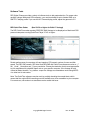
1
RED ONE™ CAMERA: OPERATIONS GUIDE
(Firmware Build 17, Version 3.4.1)
Sections:
Page
1. Before You Start
2
2. Camera Assembly
3
3. Physical Controls
5
4. Theory of Operation
9
5. Basic Operation
16
6. Sensor Menu Controls
23
7. Audio Video Menu Controls
31
8. System Menu Controls
39
Appendix A. Upgrading camera firmware
60
Appendix B. Digital Media Management
62
Appendix C: Input and Output Connectors
66
Appendix D: Post Production
75
Nov 27 2008
Copyright RED Digital Cinema
1
1. Before you start.
Congratulations on your purchase of the RED ONE camera. Carefully unpack the camera body
and any accessories. We recommend that you read this section before proceeding.
RED ONE Digital Cinema Camera
The RED ONE camera ships with a PL mount. To protect against dust or other contaminants
entering the optical path, ensure the lens cap is used at all times a lens is not mounted to the
camera. Additional lens mounts and adaptors are available for use with non-PL mount lenses.
In addition to capturing 12-bit resolution digital RAW images, the RED ONE camera supports
four channels of 24-bit audio. The RAW images may be captured at a variety of frame rates,
including single frame (still), timed interval (animation) and continuous image (video) modes.
On-line operational support can be found at www.reduser.net
Contact our service web site at www.red/support or call +1.949.206.7900
2
Copyright RED Digital Cinema
Nov 27 2008
2. Camera Assembly
Connect the power cable from the Battery Plate, RED-CHARGER or AC Power Adaptor to the
DC input on the rear of the camera body.
The RED-LCD and RED--EVF viewfinder may be mounted to the camera body using a short or
extended length RED ARM. Attach the RED ARM to the camera body using the shorter threaded
screw. There are attachment points on the camera body and on the RED RAIL TOP BRACKET.
Then attach the end of the arm with the circular locking ring to the RED-LCD or RED-EVF.
Finally connect the cable from the camera body to the RED-LCD or RED-EVF. Carefully align the
red dots on the socket and plug, and push firmly to establish contact.
Attaching the RED-LCD or RED-EVF
The RED-LCD and RED-EVF cables are interchangeable; but the outputs are not. The RED-EVF
should be connected to the upper output; a RED-LCD should be connected to the lower output.
If using RED-DRIVE, place it into the RED-CRADLE and secure it with the four thumbscrews.
Then connect the RED e-SATA cable to the RED-DRIVE and to the e-SATA input on the rear of
the camera body. (In normal operation use the right angle connector to mate to the RED-DRIVE,
and the straight connector to mate to the camera)
Remove the lens cap and mount the PL lens you wish to use. The lens will have four metal tabs
with cutouts for the registration pin in the mount. If using S4/i compatible lenses the data pins
should be oriented to 12 o’clock when mounting the lens in order to establish communication.
Attach matte box and motors, and any auxiliary power cables required to power these items.
Nov 27 2008
Copyright RED Digital Cinema
3
Insert the digital media, such as RED-FLASH 8GB or 16GB compact flash (CF) card, or connect
a RED-DRIVE hard disk drive, or RED-RAM flash drive via the RED custom e-SATA cable.
Inserting a Compact Flash card
Attach a RED-BRICK 140 battery using the v-mount battery plate, or connect an AC Power
Adaptor or a RED-CHARGER to the DC input on the rear of the camera body. Now adjust the
balance of the camera. The RED CRADLE/Universal Rail mount unit slides on 19mm rods so you
can adjust the distance to the camera back. Find the position that best offsets the weight of the
lens.
Finally tighten the butterfly locks to maintain that position. The shoulder pad/wedge plate adaptor is also designed to slide within the RED RAIL base plate until you lock it in place. You won’t
need to remove it to mount the camera on a tripod.
Power up.
Press the On/Off switch to power the camera. The rear status display will illuminate, and after
approximately 60 seconds it will display the camera PIN, firmware build and firmware version.
The P.I.N is a unique product identification number in the format ABC_123_XYZ. This code is included in the metadata recorded with each image. The PIN provides RED with tracking data for
customer service and assistance in authenticating legal ownership of the camera.
When the camera is ready for use, the lower LED to the right of the status display turns green.
4
Copyright RED Digital Cinema
Nov 27 2008
3. Physical Controls and Connectors
This section describes the physical controls and connectors on the RED ONE camera body.
A. PL Lens Mount
B. Record
C. User Keys 1 and 2
A PL mount is provided as standard with the RED ONE camera. The mount is compatible with
the majority of S35mm, 35mm and S16mm cinematography lenses. In addition, broadcast B4
mount lenses may be used if the camera is equipped with the optional B4 to PL mount optical
converter.
The PL mount includes a 4-pin S4/i data interface. This allows the camera to gather lens metadata from lenses supplied by RED and Cooke Optics. Ltd, using the S4/i protocol.
On the left side of the camera body are a RECORD key and two User Keys. User Key 1 is preassigned to AUTO WB and User Key 2 is pre-assigned to 1:1 FOCUS CHECK, however these
assignments can be changed in the KEYMAP preferences menu.
A SD Memory Card slot is located below this group of keys, which supports most SD Cards of
up to 1GB capacity. It is not possible to store video or audio data to the card SD card, however it
may be used for camera firmware upgrades and to store USER PROFILE and LOOK files.
Nov 27 2008
Copyright RED Digital Cinema
5
A Headphone
B Program HD-SDI (A)
C Program HD-SDI (B)
D HDMI Out
E Preview HD-SDI
F Video Genlock
G USB-2 (peripheral)
H USB-2 (computer)
I Audio Monitor
J Timecode
K Audio Ch 1 – 4 (1-2 Upper Left - Right, 3-4 Lower Left - Right)
L RED-EVF
M RED-LCD
N Aux / RS232
The right side of the camera contains all the video, audio and time code inputs and outputs.
From top left to bottom right, these comprise a 3.5mm stereo headphone jack, and four DIN
1.0/2.3 video connectors that support Program HD-SDI, Preview HD-SDI and Video Genlock.
Next is an HDMI output, a USB-2 “master” port for USB peripheral devices, a USB-2 “slave”
port to connect the camera to another camera or computer based controller, a 5-pin mini-XLR
audio output, a 5-pin timecode input/output and four three-pin mini-XLR audio inputs. Finally
there are two 16-pin push lock LEMO connectors that provide video, communications and
power for a RED-EVF and RED-LCD, and a 10-pin push lock LEMO connector supporting the
Aux/RS232 port that can interface to a variety of B4 lenses and lens motor control devices.
One 6-inch length DIN 1.0 / 2.3 to BNC video adaptor cable and one 9-inch length 3 pin miniXLR to mini-XLR cable plus a mini-XLR to full size XLR adaptor are provided with the camera.
Additional video and audio adaptor cables may be ordered online at www.red.com/store
Note: Cameras shipped prior to Sept 15th 2008, may have an earlier revision of the audio
board and no S4/i pins installed in the P/L mount. Contact RED customer service about
appropriate audio cables to use with these systems, and hardware upgrade options.
6
Copyright RED Digital Cinema
Nov 27 2008
A User Menus select
B Status Display
C Record & Ready tallies
D Sensor menu
E EXIT menu
F UNDO / alternate action
G Record Start / Stop H Joystick
I Audio / Video menu
J System menu
On the rear of the camera, several buttons surround a daylight readable LCD status display.
To the left of the status display are three User Menu buttons, which normally provide direct access Sensitivity, Shutter and Color Temperature menus. However the specific function of these
keys may be re-programmed by the user, if desired, to provide quick access to other functions.
Below the LCD status display are the Joystick, and Exit, Undo / alternate action and RECORD
buttons, plus the Sensor, Audio / Video and System menu buttons. The camera control menus
are logically grouped under these last three buttons to provide streamlined camera operations.
The status display reports key camera status values, and is complimented by two LED’s: the red
LED provides a record tally, while the green LED indicates the camera is ready for operation.
The five buttons above the LCD display control clip playback. From left to right, the keys are Clip
Start / Previous Clip, Play Reverse, Clip Play / Pause, Fast Fwd and Clip End / Next Clip.
Nov 27 2008
Copyright RED Digital Cinema
7
A Power On/Off switch
B Aux Power / GPIO A
C Aux Power / GPIO B
D Camera 11.5 - 17V D.C Input
E e-SATA Interface (to RED-DRIVE or RED-RAM digital magazine)
Underneath the status display key group are the Power On/Off switch (top left) two 4 pin Auxiliary
Power / GPIO outputs, 6 pin camera system POWER input and a 16 pin DRIVE interface.
Each Auxiliary Power / GPIO connector can supply 1.75 amps of unregulated 11.5 – 17V DC to
accessories such as range finders or low power lens motors. The upper connector provides a
GPI trigger (user programmable but defaulted to Record Start / Stop) and a Record Tally output.
The lower connector provides a GPI trigger (user programmable but defaulted to Single Frame
Record) and a Frame Recorded Tally output.
The DRIVE interface supplies power and data over e-SATA protocols to record REDCODE RAW
compressed video data, metadata and audio to RED-DRIVE or RED-RAM digital media.
Power Up.
To power the camera up from a RED BRICK battery, press the power on/off switch once.
To power the camera up from a RED-CHARGER, connect it via the supplied power cable. Plug
the RED-CHARGER into an AC power source and switch it on. After the green LED illuminates on
the RED-CHARGER, the camera can be powered on by pressing its On/Off switch.
To power the camera down, press the power on/off switch once.
Note: After power down, is recommended that you wait approximately 10 seconds after
the camera’s green status LED goes off before powering the camera up again. If the green
LED on the charger lights but then goes out, press the camera power On/ Off switch twice.
8
Copyright RED Digital Cinema
Nov 27 2008
4. Theory of Operation
The RED ONE Digital Cinema camera provides high performance digital imaging over a wide
range of frame rates and optical formats including Super 35mm, 35mm and Super16mm. The
camera is supplied as standard with a PL mount, and may be configured with 19 mm rods to
accommodate most cinematography lenses, matte boxes and follow focus systems. Adaptors
for 15mm offset studio and 15mm lightweight rods are also available.
In addition to compatibility with existing PL mount cinematography lenses; a select range of
S35/35mm format PL mount prime and zoom lenses are available from RED Digital Cinema.
Other lens mounts, including Canon FD, and Nikon F are available from RED and 3rd parties,
permitting the use of Nikkor and Canon photographic lenses. To use these mounts the PL
mount must be removed. It is recommended that this should be done only in a dust-free environment, as the sensor and optical path will be exposed to the elements during this process.
A B4 mount to PL mount adaptor is also available to permit use of 2/3” HD lenses on the RED
ONE camera. The optical coverage it provides is equivalent to S16 mm. Hence, the maximum
recording resolution with these lenses will be 2K RAW. (2048 x 1152 pixel progressive scan)
Mysterium™ Sensor
The Mysterium™ sensor has been specifically designed for use with the RED ONE camera, and
provides variable frame rate imaging over 1- 60fps in 4K or 3K resolution, and 1-120fps in 2K
resolution record modes.
Native color balance for the Mysterium sensor is 5,000 degrees Kelvin, but may be electronically compensated for any color temperature in the range 1,700 to 10,000 Kelvin. White Balance presets are available for Tungsten (3200K) and Daylight (5600K) lighting; the camera may
also calculate a color neutralizing White Balance value using a standard white card technique.
Mysterium includes integrated 12-bit resolution analog to digital conversion, capable of delivering up to 11 stops of dynamic range when operating in daylight at a sensitivity of 320 ISO.
Image Processing
Images received from the Mysterium sensor are formatted as pixel defect corrected (but not
color processed) 12-bit RAW data - similar in image quality to a high end digital stills camera.
The sequence of 12-bit RAW images received from the sensor is compressed using proprietary
wavelet based REDCODE RAW compression. The RAW data recorded is independent of the
RGB signal monitored from the monitoring path. ISO, white balance or other RGB color space
adjustments made to the monitoring path are not burned into the recorded 12-bit RAW data.
Images can be stored on a high-speed Compact Flash, RED-DRIVE or RED-RAM media.
Nov 27 2008
Copyright RED Digital Cinema
9
The camera’s monitoring path converts 12-bit RAW sensor data white balanced 10-bit 1280 x
720 pixel RGB 4:4:4 video. This signal may be modified using ISO, white balance or other RGB
color space adjustments and provides monitor feeds for the RED-EVF, RED-LCD, Preview HDSDI and HDMI outputs.
Audio Recording
The RED ONE includes four channels of analog audio input as well as a headphone monitor
and balanced analog audio output. Digitized audio is available on the HDM, Preview HD-SDI
and Program HD-SDI outputs.
Line level analog audio inputs are immediately digitized at 24 bits per sample at 48KHz sample
rate. Microphone level audio inputs are routed via an adjustable gain pre-amplifier before digitization; gain is generally not applied to Line level inputs, but it may be set to +10dB if desired.
Microphone Input Levels
Recorded levels are affected by the gain setting of the microphone input preamplifier.
At +10 dB, the microphone input level equivalent to Full Scale is +3 dBu (1.1 Volts RMS)
At +54 dB, the microphone input level equivalent to Full Scale is -36 dBu (0.013 Volts RMS).
Line Input Levels
Recorded levels follow the level of the incoming signal.
The input level equivalent to Full Scale is +18 dBu (6.5 Volts RMS).
To achieve 14 dB of input headroom set the nominal input to +4 dBu (1.3 Volts RMS).
Video Monitoring Outputs
In its default configuration, the RED ONE camera can simultaneously support a RED-EVF,
RED-LCD, 3 HD-SDI outputs and one HDMI output, with two of these outputs supporting full
GUI overlay graphics.
Default setting for GUI support is RED-EVF and RED-LCD. However, if either one of these is
not present, full GUI overlay support is automatically enabled on HD-SDI and HDMI outputs.
RED-EVF: 1280 x 848 resolution RGB 4:4:4 progressive video display with Surround View,
frame guides and safe action / title overlays, zebra and false color exposure overlays, waveforms, camera status and operation menus.
RED-LCD: 1024 x 600 resolution RGB 4:4:4 progressive video display with Surround View,
frame guides and safe action / title overlays, zebra and false color exposure overlays, waveforms, camera status and operation menus.
10
Copyright RED Digital Cinema
Nov 27 2008
PROGRAM HD-SDI: When in record mode, these connectors provide two extra copies of the
HD-SDI PREVIEW signal. When in playback mode, these connectors provide a dual-link 10-bit
RGB 4:4:4 video signal.
PREVIEW HD-SDI: 1280 x 720 resolution 10-bit 4:2:2 video output (720p 50.00 /59.94 Hz).
PREVIEW HDMI: 1280 x 720 resolution 10-bit 4:2:2 video output (720p 50.00 /59.94 Hz).
Note: If a RED-EVF or RED-LCD is connected, the PREVIEW HD-SDI and HDMI outputs
will provide Surround View, frame guides, safe action / title, and timecode / clip name. If
both RED-EVF and RED-LCD are connected, these outputs only support Surround View.
Note: Only if a RED-EVF or RED-LCD is connected, the HDMI output can also support a
1280 x 848 resolution video output with Surround View, frame guides, safe action / title,
timecode / clip name, waveform, and camera status and operation menu overlays. This
signal should be compatible with the majority of DVI based SXGA+ computer monitors.
To select between these modes, press the SYSTEM menu key, and then MONITOR.
Press the joystick in, and then push the joystick to the right to highlight PREVIEW.
Rotate the joystick to select VIDEO (720p) or MENUS (DVI). The default is VIDEO (720p)
Press the EXIT key to return to the main camera menu. The Preview Output setting will be held
in camera memory. Once it is set it will not need to be re-set when power cycling the camera.
RED-LCD and RED-EVF
The optional RED-LCD and RED-EVF are specialized video monitors, that may be attached to
the camera body, and provide a variety of user tools to assist framing, focus and exposure.
-
Surround View, which is an additional visible area outside the actual recorded image.
-
Frame guidelines show common film presentation and television formats such as 2.40:1
and 1.85:1, picture center, and/or television aspect ratios such as 16:9, 14:9 and 4:3.
-
Focus is aided by the high resolution of the displays, 1:1 Focus Check function, and two
user selectable waveform based focus assist meters.
-
Exposure is aided by dual zebras a false color meter and Luma and RGB histograms.
Nov 27 2008
Copyright RED Digital Cinema
11
System information including instantaneous frame rate, sensitivity, shutter speed, color temperature, recording format, clip name, timecode, battery and media remaining is provided in
the RED-LCD or RED-EVF monitor outputs, and the rear status display on the camera back.
For applications where a RED-LCD or RED-EVF are not desired – for example working on a
crane – the Surround View video, frame guides, and exposure overlays are also available on
the Preview HD-SDI output, providing remote camera monitoring up to 200 ft away.
Digital Magazines
REDCODE RAW compressed video, time code, audio and metadata, may be recorded to onboard or attached digital media devices including RED-FLASH: RED record speed verified 8GB or 16GB Compact Flash cards.
RED-DRIVE: A hard disk media based Digital Magazine of 320GB capacity.
RED-RAM: A solid-state flash media based Digital Magazine of 128GB capacity.
Note: Digital Magazines may be directly connected to a computer via FireWire or USB-2.
Each clip is recorded with a unique clip name and with all the appropriate elements of the clip –
REDCODE RAW files and QuickTime Reference files placed in a clip folder (.RDC)
12
Copyright RED Digital Cinema
Nov 27 2008
All clips are in turn placed in a root directory (.RDM) The root directory (folder) contains all the
clips recorded on that specific piece of digital media, so copying of clips from the digital magazine to backup media may be performed by a single drag and drop operation.
Record Indication
On record, the RED ONE camera provides a variety of record tallies. Timecode, normally displayed in white colored text, will turn red, and a small red dot will appear in the top left corner
of the video monitoring outputs. The upper LED to the right of the status display screen will
turn red, and if using an EVF, the front LED will also turn red. If media is not present, the camera will provide a warning as follows – RECORD ERROR NO_DIGIMAG.
Metadata
RED ONE cameras record Metadata, which is data that describes the precise characteristics of
the picture and sound data, in each frame of footage. This may include camera specific setup
information, project and clip management information, Edge code, Time code, date and GMT,
lens parameters, audio settings and any video image processing information.
Clip Naming Conventions
When you push record, the camera names the clip being recorded on the digital media. The
format of the clip name is Camera Letter + Reel Number + Month + Day + ** where ** is a two
digit alphanumeric random number generated by the camera for each file
E.g. A001_C002_0502A6.RDC
Where: A = camera A, 001 = reel 001, C002 = clip 002, and 0502 = May 02
And A6 is a two digit alphanumeric random number generated by the camera. This number
helps avoid duplicate file names if two cameras are inadvertently named A on the same set.
Three cameras identified as A, B and C can therefore have individually recognizable clips
A001_C001_0502**.RDC
Nov 27 2008
B001_C001_0502**.RDC
Copyright RED Digital Cinema
C001_C001_0502**.RDC
13
A single camera identified as A can have individually recognizable reel numbers, such as
A001_C001_0502**.RDC,
A002_C001_0502**.RDC, and A003_C001_0502**.RDC
A single camera identified as A can have individually recognizable clip numbers, such as
A001_C001_0502**.RDC,
A002_C002_0502**.RDC, and A003_C003_0502**.RDC
Note - Even if the same Reel number and / or camera name are reused, the use of the two
character random files generated non-duplicate file names, such as
A001_C001_0502A6.RDC,
A001_C001_050267.RDC, and A001_C001_0502F8.RDC
Under normal operation, the reel number increments each time the camera formats a new
piece of digital media, up to a maximum value of 999. However the reel number may be manually reset at any time to 001or other desired value.
A001_C001_0502**.RDC and then force to 1 to create A001_C001_0503**.RDC
SMPTE Timecode
As each recording is made, the RED ONE camera records two independent timecode tracks.
Edge Code is a SMPTE timecode track that always starts at 1.00.00.00 on the first frame of
each piece of digital media. It is a sequential code that is continuous from frame to frame and
also between clips. Edge Code is equivalent to RUN RECORD as used on broadcast cameras.
Time Code is a SMPTE timecode track that syncs to the camera’s clock, or if operated in Jam
Sync mode, syncs to an externally supplied SMPTE master timecode signal. It is therefore a
sequential code that is continuous from frame to frame, but discontinuous between clips.
Note: Time Code and Edge Code are only output from the 5-pin timecode connector if
OUTPUT is enabled in the TIMECODE setup menu, but are always embedded in HD-SDI.
When in Varispeed or Timelapse recording modes, the timecode counters are updated at the
same frame rate as the recording. This means valid SMPTE timecode is created without count
jumps that would affect clip playback or editing. If using an external timecode source with Jam
Sync enabled, the clip’s master time reference point is the first frame of the recorded clip.
When in Loop Record mode, the Edge Code will become discontinuous between clips, because frames copied into the cache memory are discarded. This may lead to problems with
applications that assume a continuous timecode sequence. It is therefore recommended that
Time Code be selected when operating this recording mode.
14
Copyright RED Digital Cinema
Nov 27 2008
Power consumption
The camera draws approximately 75 watts in a typical configuration. A RED-BRICK 140Wh battery will run the camera and typical accessories for about 90 minutes. The camera is normally
cooled by passive convection from the camera body, assisted as required by a fan.
When using the RED-CHARGER, recharge time for a single RED-BRICK battery is 200 minutes.
The battery can also be partially charged, to approximately 80% capacity, in 120 minutes.
Charge times may be significantly longer if using another V lock compatible battery charger.
Note: V lock batteries from other manufacturers may be used with the RED ONE camera
provided that they meet minimum current and voltage draw requirements. In general, avoid
batteries rated at less than 7Ah and 90Wh. Battery status is provided in the camera’s user
interface (GUI) when using REDBRICK batteries. Other battery types will report as “D.C”.
Operating the camera from the RED-CHARGER.
Plug the RED-CHARGER into an AC power source between (120 – 240V). Plug one end of the
supplied 6-pin power cable into the Aux power output of the RED CHARGER and the other end
into the DC power input of the camera. Now turn on the RED-CHARGER.
When the LED above the charger’s Aux power output turns green, you can turn on the camera.
Note: The maximum sustainable power load of the RED-CHARGER is 100W @13.8V. The
output of the charger is over current protected, and will shut down if an excess load condition occurs. If the output trips for any reason, remove any external loads from the camera,
such as lights, motors etc, turn off the RED-CHARGER and repeat the above procedure.
Nov 27 2008
Copyright RED Digital Cinema
15
5. Basic Operation
This section describes the basic controls of the RED ONE camera and how to initiate a project.
Control System and Status Display
Command inputs to the camera are made from the rear status display and associated buttons.
A - Quick Access
Access to Exposure, White Balance and Shutter Speed
B - Menu Access
Access to Sensor, Video and System menus
C - Menu Control
Exit and Undo keys
D - Joystick
The joystick is a multi-axis controller used to navigate camera menus.
E - Record
Record Stop / Start key
The five buttons above the display control clip playback. From left to right, the keys are Clip Start
/ Previous Clip, Play Reverse, Clip Play/Pause, Fast Fwd and Clip End / Next Clip.
Note: Quick Access keys may be re-programmed if desired. Enter the menu that you wish
assigned to one of these keys, then press and hold the A, B or C key until the camera reports “ User button A/B/C has been assigned to this menu” Subsequent presses of this key
will return the camera to that same menu location.
16
Copyright RED Digital Cinema
Nov 27 2008
Status Display
The status display mounted at the rear of the RED ONE camera provides a snapshot of the
camera setup. The elements include –
Timecode / Status
reports current timecode value, clip name or system messages
ASA Value
reports current exposure index
Project Frame Rate
reports the project frame rate, 24.00 fps in this example
Timecode
reports timecode lock status
White Balance
reports current color temperature
Media
reports remaining media capacity in %
Battery
reports remaining battery capacity or connection to AC power
Shutter Speed
reports current exposure time
Format
reports video recording format, 4K RAW in this example
Note: The timecode value reported is Edge Code or Time Code, as selected by the user
in the TIMECODE menu. During recording, the Clip Name is reported in this display field.
Nov 27 2008
Copyright RED Digital Cinema
17
Setting up a project.
Before recording, the camera must be instructed to follow a Record Quality, Frame Rate and
Resolution. These values are set in the PROJECT sub menu located in the SYSTEM menu.
1. Press the SYSTEM menu key, then PROJECT. This highlights the PROJECT sub-menu
2. Push the joystick right, then press to enter the CONFIGURE menu to set the QUALITY
Quality. Choose between REDCODE 28 and REDCODE 36. Default is REDCODE 36.
Note: Choosing REDCODE 36 limits available frame rates and resolutions to CF cards.
Note: Leave MAX box checked, unless recording 4K 16:9 and needing real time decode.
3. Next select the project TIME BASE (this parameter was formerly known as Frame Rate)
Time Base: Choose between 23.98, 24.00, 25.00 or 29.97fps. The time base establishes the
base frame rate for a project, and so should not be adjusted. Use Varispeed if shooting above
or below this base frame rate for slow motion effects.
Note: 2K and 3K record resolutions also support 50.00 and 59.94 fps Project Time Bases.
4. Next select the project RESOLUTION
Resolution. Choose 4K, 3K or 2K, or 2:1 variants. Use 2K or 2K 2:1 for S16mm/B4 lenses.
Note: A project can only support one project Time Base as this defines the frame rate to be
used for timecode and for clip playback. It is also the primary frame rate for acquisition, but
variable speed (over-crank and under-crank) recordings can be made above and below this
base frame rate. On playback these recordings will be displayed at the Project Frame Rate
Note: If operating on a multi-camera production, enter a different Camera I.D for each
camera using the SLATE menu; otherwise skip this step; the camera is ready to shoot.
18
Copyright RED Digital Cinema
Nov 27 2008
Recording
Check that you have a RED-DRIVE attached, or Compact Flash card inserted in the camera. To
initiate a recording, press either RECORD button. Press once to begin recording and again to
stop recording. The camera will automatically create a file name for every clip recorded on the
digital magazine or media.
REDCODE RAW data recordings store the Color Temperature and Exposure (ISO) and any RGB
color processing values you use in the monitor path as metadata. This metadata is used in RED
Alert! or other post production software as initial white balance, exposure and color correction
points i.e. you can change these if you wish when you process the RAW footage.
Time Code and Edge Code values used by the camera are Non Drop Frame (NDF), Drop Frame
(DF) is not supported. Audio is captured at 48KHz 24-bit resolution per channel, uncompressed.
Digital media should be treated with equal care as exposed film or a videotape master. We
recommend storing digital media that contains your footage in a secure location and backing up
the data on another digital media, such as data tape or a hard disk drive.
Each clip is recorded to the digital media in a separate folder and with a unique clip name. To
copy the clip from the digital media to a Macintosh or Windows computer, just drag and drop its
folder to the computer’s storage device. If you open the Clip folder, it will look like this –
The Clip folders (.RDC) are held in a root directory (.RDM) on the digital magazine. In each
folder there will be one or more REDCODE RAW data files (.R3D) containing RAW sensor data,
plus audio and metadata, and four QuickTime reference movies, which allows a QuickTime
Player to display the RAW data at _F full, _H high, _M medium or _P proxy resolutions.
Double click on one of the QuickTime reference movies to see a preview of the .R3D file. Playback frame rate will depend on the processor speed of your computer. If the frame rate is too
low, select a smaller QuickTime movie.
Note: to operate with QuickTime under Macintosh OSX, install the supplied REDCODE
RAW plug-in available at www.red.com/support. Windows is not currently supported.
Nov 27 2008
Copyright RED Digital Cinema
19
Playback
Playback of recorded clips is available on-camera using the Transport Control Keys.
The I> key is used to enter PLAYBACK mode, and to initiate playback of the last recorded Clip.
Press it once to enter Playback mode, and a second time to start playback. Once in clip playback, this key acts as a Play/Pause toggle.
The >> key permits the Clip to be played back at higher speeds. Each press of this key cycles
clip playback between 1 x, 2 x, 8 x and 32 x speed playback.
The << key permits the Clip to be played back in reverse. Each press of this key cycles clip playback between – 1 x, - 2 x and - 8 x speed playback.
The I< key cues the Clip to its Start Frame. If already at the Start Frame, pressing this key again
will cue to the Start Frame of the previous clip recorded on the digital media, if one exists.
The >I key cues the Clip to its End Frame. If already at the End Frame, pressing this key again
will cue to the Start Frame of the next clip recorded on the digital media, if one exists.
Note: It is not necessary, to exit Playback mode prior to the next recording. To exit playback mode, either press the RECORD key, or press the EXIT key to the left of the joystick.
When in playback, all cursors will be disabled, and the camera provides a clean feed of the recorded video signal at 1280 x 720 resolution on the Preview HD-SDI and HDMI outputs.
Depending on the capture frame rate, pull down will be added to create a standard 1280 x 720
progressive scan 59.94Hz or 50.00 Hz high definition video signal. At this time there is no embedded SMPTE timecode on either the Preview HD-SDI or HDMI outputs, however they both
include 4 independent channels of 24-bit 48KHz audio.
Note: If PLAYBACK MODE preference is set to 1080p, HD Preview HD-SDI and HDMI outputs switch 1920 x 1080p progressive scan 10-bit 4:2:2 at 23.98, 24.00, 25.00 or 29.97 fps.
Note: If PLAYBACK LOOK preference is set to CLIP, the color adjust metadata will be read
fro the recorded clip. If set to CAMERA it will be taken from the current camera settings.
20
Copyright RED Digital Cinema
Nov 27 2008
Monitoring.
RED-LCD and RED-EVF monitors are factory preset digital displays. There are no saturation,
peaking or contrast adjustments as found on analog monitors to correct color reproduction.
Monitor outputs on the RED ONE camera are set up for REC 709 gamma and color space.
Image intensity can be adjusted to compensate for ambient lighting conditions. For the REDLCD, use the Up / Down keys on top of the display. For the RED-EVF use the rotary encoder.
To assist with exposure, all monitor outputs can display either a dual Zebra pattern or a False
Color exposure meter overlaid on the video. In addition the RED-EVF and RED-LCD outputs
can display a RGB histogram, exposure “stop lights” and RAW sensor data exposure meter.
RED-LCD Controls.
The top of the RED-LCD provides two round and two triangular keys. On the left is User Key 5
whose function can be defined the USER KEY preferences menu. The two triangular keys in
the center are used to increase or decrease backlight intensity. The key on the right switches
the display between Video plus Frame Guides and Menus, to Video plus Frame Guides only.
RED-EVF Controls
The RED-EVF comprises the following components: high-resolution color display, focus ring,
rotary encoder / switch, two user definable and one fixed function button.
The color display provides a 1280 pixel x 848-pixel resolution progressive scan color image
equivalent to viewing a 17” reference color monitor from a distance of approximately 4 ft.
The focus ring on the viewfinder may be adjusted for optimal subject focus for your eye. The
available diopter range is +1.5 to -2.0.
Nov 27 2008
Copyright RED Digital Cinema
21
The rotary encoder / switch may be used to adjust a variety of parameters. These include the
EVF Intensity, but also camera parameters such as Ch1 Audio Level or Ch 2 Audio Level, and
Shutter speed, Varispeed frame rate and ISO setting.
To activate this control, push the switch once. Rotate the switch until the white selection box
overlays the parameter you wish to adjust. Then press the switch to lock that selection in.
Rotating clockwise increases the parameter value, counterclockwise decreases the parameter
value. Push the switch once more to lock the parameter and exit the parameter adjust mode.
INT
CH1
CH2
SHU
VAR
ISO
OFF
adjusts EVF backlight display intensity
adjusts Ch 1 microphone audio level
adjusts Ch 2 microphone audio level
adjusts Shutter speed
adjusts Varispeed frame rate
adjusts Sensitivity rating of monitoring
EVF control – Active / Disabled
The fixed function button (located closest to the focus ring) selects 1:1 FOCUS CHECK mode.
When selected this shows the central region of the Mysterium sensor in native 4K resolution.
Note: This function is not available during RECORD.
The central pair of buttons is User Keys 3 and 4. In their default settings USER 3 turns COLOR
TOOLS (monochrome or false color) On/Off, and USER 4 turns the METER (e.g. WAVEFORM
or FOCUS ASSIST) On/Off. The functions of USER 3 and USER 4 may be changed if desired in
the USER KEY preferences menu.
Using external HD-SDI or HDMI monitors.
To aid external monitor alignment, the RED ONE camera provides a range of test signals including SMPTE Bars, Back and White Fields, Luma and Chroma Ramps, and a Chip Chart.
Note: the internal test signals cannot be recorded; they are provided to align external
video recorders or monitors connected to the camera via the HD-SDI or HDMI ports.
22
Copyright RED Digital Cinema
Nov 27 2008
6. SENSOR MENU Controls
This section describes how to set sensor specific menu parameters including Sensitivity, Shutter Speed, Color Temperature, Varispeed and Timelapse. To access these functions, press the
SENSOR menu key or one of the direct access keys to the left of the status display.
Note: Sensitivity and Color Temperature metadata values are stored as metadata and are
also used to modify the RED-LCD, RED-EVF, Preview HD-SDI and HDMI monitor outputs.
They do not affect 12-bit REDCODE RAW data recording, the stored metadata values may be
used by REDCODE RAW compatible NLE and image processing applications if desired.
Sensitivity
Sensitivity: adjusts the camera’s operating sensitivity. The default sensitivity value is ISO 320,
adjustable in 1/3rd stop increments from ISO 100 to ISO 2000. When sensitivity is adjusted, the
camera metadata logs the change and the monitor path reacts accordingly.
Color Temperature
Color Temperature: adjusts the purity of white reproduction of the RGB monitoring paths at
different Color Temperatures of ambient light. Factory default is 5,600 degrees Kelvin.
Preset values are available for Tungsten (3,200K) and Daylight (5,600K). The operator may also
manually set any other Color Temperature in the range 1,700 to 10,000 degrees Kelvin.
The Automatic White Balance function allows the camera to calculate a Color Temperature that
will render a white object as white. AWB mode analyzes the central 25% of the image visible in
the monitor.
To use Auto WB, place a white or gray object under the ambient light, select the Auto WB parameter and then press the Joystick once. Auto WB may also be assigned to a User Key.
Nov 27 2008
Copyright RED Digital Cinema
23
Tint
Color Temperature calculations assume a pure light source that may not be true in the specific
scene the camera is imaging. To compensate for any residual colorcast, the TINT parameter
can adjust the RGB color balance with a compensating Magenta - Green color component.
Note: Pressing Auto WB calculates a new Tint value. This is maintained if the Color Temp
is adjusted via the Manual WB parameter. If you select the Tungsten or Daylight presets,
Tint will be reset to zero, which is the default value.
Shutter Menu
Adjusts exposure time of each frame captured by the Mysterium sensor. Shutter speed presets
are available for all common speeds (and corresponding angles) at 24 / 25 fps and 50 / 60 fps.
Preset shutter speeds may be adjusted using the RELATIVE and SYNCRO shutter parameters.
Genlock: references Shutter scan start time (phase) to an external Tri-Level Sync genlock signal. For 3D and multi-camera, permits scan time and scan phase of all cameras to be matched.
Mode: enables one of three following shutter modes. Default selection is Normal.
Normal: Shutter Speed is defined exclusively by the Shutter Speed setting.
Syncro: Shutter Speed is defined by Shutter Speed, but modified by Syncro setting.
Relative: Shutter Speed is defined by Shutter Speed, but modified by the capture fps.
24
Copyright RED Digital Cinema
Nov 27 2008
Note: If operating in Relative or Syncro modes, the shutter speed is reported in yellow text.
Note: If the operator requests a shutter speed (angle) that is outside the capability of the
camera in that mode, the actual shutter speed (angle) used will be reported in red text.
Shutter Speed
When operating in Normal mode, the Shutter Speed value used by the camera is fixed, i.e. it
is independent of the image capture rate. This is opposite from a mechanically shutter camera.
Decreasing Shutter Speed will more light falls on the sensor, increasing exposure and motion
blur on any objects moving within the frame. As Shutter Speed increases less light falls on the
sensor, decreasing exposure and motion blur on objects moving within the frame.
Speed: Exposure times presets include: 1/24, 1/25, 1/30, 1/32, 1/33, 1/40, 1/48, 1/50, 1/60,
1/96, 1/100, 1/120, 1/125, 1/192, 1/200, 1/250, 1/384, 1/400, 1/500, 1/696, 1/800, 1/1,000,
1/1,200, 1/2,000th sec.
When operating at 23.98 or 24.00fps, these equal common shutter angles of
1/32nd
270 deg
1/96
90
1/48
180
1/192
45
1/60
144
1/384
22.5
Relative: When operating in this mode, the Shutter Speed values are proportionately reduced
or extended to correspond to changes in the instantaneous capture frame rate.
This mode is analogous to use of a fixed shutter angle on a mechanically shuttered camera.
E.g. Enabling Relative mode with 1/48th sec shutter at 24fps will mean 1/96th sec for 48fps, and
1/16th sec for 8fps. This achieves the same visual result as setting a180 degree shutter.
Nov 27 2008
Copyright RED Digital Cinema
25
Syncro: When operating in this mode, the Shutter Speed values may be proportionately reduced or extended to tune exposure time to a precise value. Range 10 – 90. Default 50.
E.g. Setting Syncro to 53 with a 1/60th sec shutter is equal to 1/56.6 sec exposure time.
Phase: provides a delay relative to the start of the frame for the exposure time. Phase may be
adjusted over the range - 45 to + 45 degrees. Default value is 0.
Note: To Convert Shutter Speed to Angle Equivalent
Equivalent Degrees = (Shutter Speed x Frame Rate x 360)
E.g. = (1/48 x 24 x 360) = (8640 / 48) = 180
Shutter
Degrees
Shutter
Degrees
1/32
270
1/120
72
1/48
180
1/192
45
1/50
172.8
1/348
22.5
1/60
144
1/696
11
1/96
90
1/1000
8.6
Note: To Convert an Angle to an Equivalent Shutter Speed
Equivalent Shutter = 1 / ( Frame Rate x 360 / Angle )
E.g. = 1/ (24 x 360 / 180) = 1/ (8640 / 180) = 1 / 48
Degrees
Shutter
Degrees
Shutter
270
1/32
72
1/120
180
1/48
45
1/192
172.8
1/50
22.5
1/348
144
1/60
11
1/696
90
1/96
8.6
1/1000
26
Copyright RED Digital Cinema
Nov 27 2008
Varispeed
The Varispeed menu supports Variable Frame Rate recording at speeds faster or slower than
the Project Frame Rate and Frame Rate Ramping. Varispeed recordings can be initiated by
pressing the Record key, or by GPI trigger.
Note: In all Varispeed modes, audio recording is disabled.
Note: In Varispeed modes timecode is written to digital media at a rate equal to the instantaneous capture rate. This ensures that the recorded REDCODE RAW data has valid and sequentially incrementing timecode for use by non-linear editing devices.
Note: In Varispeed, the frame rate display turns yellow, the audio panel reports VARISPEED.
Varispeed: Before recording, enable this function by checking the Varispeed checkbox.
Ramp: enables a speed ramp; a transition over Time from the Frame Rate to an End Rate
On-Record: On recording start, the capture frame rate will immediately start transitioning from
the Frame Rate to the End Rate.
On-Event: On recording start, the capture frame rate starts out at the Frame Rate, the start of
the transition to the End Rate occurs only when an external GPI trigger has been received.
Nov 27 2008
Copyright RED Digital Cinema
27
Framerate: enables the user to choose any single frame rate. Minimum frame rate is 1 fps;
maximum frame rate is a function of REDCODE setting, record resolution and media type:
REDCODE 28
RED 8GB CF RED 16GB CF RED DRIVE
RED RAM
2K 2:1
100 fps
120 fps
120 fps
120 fps
2K 16:9
100 fps
100 fps
100 fps
100 fps
3K 2:1
50 fps
60 fps
60 fps
60 fps
3K 16:9
30 fps
50 fps
60 fps
60 fps
4K 2:1
25 fps
30 fps
30 fps
30 fps
4K HD
25 fps
30 fps
30 fps
30 fps
4K 16:9
25 fps
30 fps
30 fps
30 fps
REDCODE 36
28
RED 8GB CF RED 16GB CF RED DRIVE
RED RAM
2K 2:1
75 fps
100 fps
120 fps
120 fps
2K 16:9
75 fps
75 fps
100 fps
100 fps
3K 2:1
30 fps
30 fps
50 fps
60 fps
3K 16:9
30 fps
30 fps
50 fps
60 fps
4K 2:1
25 fps
30 fps
30 fps
30 fps
4K HD
----
25 fps
30 fps
30 fps
4K 16:9
----
25 fps
25 fps
30 fps
Copyright RED Digital Cinema
Nov 27 2008
Time: When Ramp is enabled, this value specifies the transition time to be used by the camera
between the (start) Frame Rate and the End (frame) Rate. Default value is 5 seconds.
End Rate: When Ramp is enabled, this value specifies the final (ending) speed of the ramp in
frames per second. When a ramp transition has been completed, the camera will continue to
record at the End Rate until the end of the Recording.
Note: When in Varispeed modes the camera maintains the last exposure time selected (unless
the requested frame rate requires a shorter exposure time) to provide a constant exposure. If a
variable exposure is required set the Shutter Mode to Relative - this is a fixed angle setting.
Timelapse
The Timelapse menu supports single frame image capture and step frame recording under the
control of an internal Intervalometer, side RECORD key or an external (GPI) trigger.
Enable: After making any adjustments in the Timelapse menu, check the Enable box to enter
these values and enable the Timelapse record mode. The UI indicates by changing the top left
frame rate display from fps to TL, and the lower right audio level display to TIMELAPSE.
Trigger Mode: Specifies if the camera is to use a fixed Interval of time or wait for a side record
command or external GPI contact closure to initiate the next frame capture.
Interval: the camera waits for the period of time defined by the Interval parameter.
One-Shot: the camera waits for a side record command or external GPI contact closure.
The default setting is One-Shot.
Nov 27 2008
Copyright RED Digital Cinema
29
Speed: Specifies the shutter speed to be used during Timelapse. This control is the same as is
available in the Shutter menu, but it provides access to additional shutter speeds that may be
used in Timelapse recording.
The additional exposure time presets are 1/2, 1/3 1/4, 1/6, 1/8, 1/12, 1/16 second.
Step Print: Specifies the number of times each single frame captured in Timelapse mode is to
be recorded to the digital media. Available range is 1 to 10 frames. Default value is 1 frame.
Interval: Specifies the number of seconds the camera will wait before the next image is captured. Range is 1 to 1024 seconds. Default setting is 5 seconds.
Burst Type: Specifies the type of burst recording, either Repeat or Unique. Default is Unique.
Repeat: Specifies that each frame captured during the burst record be repeated. That is for
each Timelapse event, a single frame is repeated N times, where N is the Step print value.
Unique: Specifies that each frame captured during the burst record is unique. That is for each
Timelapse event, N frames are captured and recorded, where N is the Step print value.
Note: When recording in Timelapse mode, the RECORD tally lamp will remain illuminated.
Each successive event uses the next available Edge Code and Time Code value and uses the
existing clip name. This results in a complete Timelapse sequence with a single clip name and
correct timecode sequence. To exit Timelapse mode press the RECORD button.
30
Copyright RED Digital Cinema
Nov 27 2008
7. AUDIO / VIDEO MENU Controls
This section describes monitor path parameters such as viewfinder, and RGB color and gains.
These parameters are accessed from the VIDEO menu access key.
Available sub menus include VIEW, VIDEO, VIEWFINDER, AUDIO and HEADPHONE
VIEW
The VIEW sub menu allows the user to choose the mode of monitor path image processing.
The default selection is REDspace.
REDspace: monitor path image processing uses custom REDspace tonal response curve.
REC709: monitor path image processing uses SMPTE REC 709 tonal response curve.
RAW: monitor path image represents the RAW sensor data, bypassing the color matrix.
Video Menu
The four available submenus are LOOK, COLOR, GAIN and TONE
Note: Color and Gain and Tone values used by the monitor path are stored as metadata for
use in REDCODE RAW compatible image processing applications. They can be used to visualize a specific color “look” but do not affect the REDCODE RAW recorded data.
LOOK menu
The LOOK menu permits Video, Gain and Tone values to be exported or imported to an SD
Card. Look (.RLK) files may be read by another camera, but not by REDALERT! or REDCINE.
Clear: Resets the settings for Color, Gain and Tone menu parameters to their default values.
Nov 27 2008
Copyright RED Digital Cinema
31
Import: The current settings for Color and Gain parameters will be overwritten by the values
stored on the SD Card. The available LOOK files will be listed in alphabetical order, e.g. PROFILE_1
PROFILE_2
MAGENTA_TINT
Export: The current settings for Color and Gain parameters are stored to the SD Card. The
camera generates a file name of the format PROFILE_**.RLK
Note: you may edit LOOK filenames on a computer, but do not change its extension
(.RLK) or the camera will not recognize it. Restrict file names to 12 characters.
Color sub menu:
The Color sub-menu selects various image processing parameters that may be applied to the
monitor path. They do not affect the actual REDCODE RAW data being recorded.
Saturation: adjusts color saturation. Range is 0.0 (monochrome) to + 2.0 (super color)
Exposure: adjusts exposure compensation. Available exposure range is – 2.0 to +4.0
Brightness: adjusts brightness without crushing highlights. Available range is – 10 to + 10
Contrast: adjusts the overall contrast of the image. Range is -1.0 (flat) to +1.0 (max contrast)
Gain sub-menu
The Gain sub-menu selects various image processing parameters that may be applied to the
monitor path. They do not affect the actual REDCODE RAW data being recorded.
Master: adjusts the gain of RED, BLUE and GREEN equally. Range is 0.0 (no Red) to +4.0
Red Gain: adjusts the gain of the RED channel only. Range is 0.0 (no Red) to +4.0
32
Copyright RED Digital Cinema
Nov 27 2008
Blue Gain: adjusts the gain of the BLUE channel only. Range is 0.0 (no Blue) to +4.0
Green Gain: adjusts the gain of the GREEN channel only. Range is 0.0 (no Green) to +4.0
TONE menu
The TONE sub-menu allows a Tonal Response Curve to be overlaid on the video monitor path.
The curves parameter values are stored in metadata, and may be visualized in RED ALERT!
post-production software as Curve data.
Curve: This checkbox enables the Tonal Response Curve. Default setting is enabled.
Define: Selects the curve control point to be adjusted - Black, Toe, Center, Knee or White.
Each control point comprises two independent values, one each for X and Y-axis locations.
X: Adjusts the location of a control point along the X-axis on the tonal response curve.
Y: Adjust the location of a control point along the Y-axis on the tonal response curve.
Viewfinder Menu
This menu permits the operator to adjust operation of the viewfinder.
Color: When checked, forces the RED-EVF and RED-LCD outputs to monochrome or a false
color exposure assist or Edge Highlight
In Monochrome, the color component of the image is removed.
In False Color the color component of the image is replaced by an overlay of colored bands
representing the exposure levels with the image. Bluer colors represent underexposed areas,
green is 18% ND, yellow and red colors represent more exposed areas.
Nov 27 2008
Copyright RED Digital Cinema
33
This image reflects the following mapping relative to stops of exposure and 0 - 108 IRE. Note
the green and pink bars that allow quick exposure setup for 18% ND and skin tones.
This is the corresponding white balanced but otherwise unprocessed, source image – captured
at late morning at exposure index A320, 24fps, 1/48th sec shutter and no filtering.
34
Copyright RED Digital Cinema
Nov 27 2008
Note the transition of false color in the clouds, indicating clip point was almost reached, the
light grey chair is exposed at approximately 18% gray, and the foliage falls in the shadows.
Edge Highlight
With Edge Highlight selected, items that are in focus are outlined in red over monochrome.
Analysis Menu
Meter: allows the operator to choose an “always on” signal analysis. Selections include Spot
Meter, Luma Histogram, RGB Histogram and MONO (RGB without color) Histogram.
If Spot Meter is selected, a red rectangular box will appear centered on the center cursor of
the image. The size of this sample box can be adjusted by rotating the Joystick, and its location can be adjusted by moving the joystick in X and Y directions. Press the joystick to fix the
sample box. The average IRE value of the pixels in the sample box is shown in the lower section of the full camera display.
If Luma, Mono or RGB Histogram is selected, a corresponding histogram illustrates the exposure distribution. A Clip Meter (like a traffic light – but red, blue and green) compliments the
histograms. When either of the R, G, and B channels have 1% of their pixels at maximum (clip)
value, the corresponding channel clip light will illuminate.
Nov 27 2008
Copyright RED Digital Cinema
35
Assists: allows the operator to choose a signal analysis waveform. Selections include Waveform Exposure, RGB Parade Histogram, Focus Assist and Focus Overlay.
If Waveform is selected, a color-coded waveform illustrates the exposure values using the full
width of the lower section of the camera display. As exposure reaches maximum, waveform
color changes to yellow and then red. At minimum exposure, the waveform color changes to
light blue then dark blue. These colors match those used in the False Color Meter.
If RGB Parade is selected, a corresponding histogram illustrates the exposure distribution in
the R, G and B channels using the full width of the lower section of the camera display.
If Focus Assist or Focus Overlay is selected, a full screen width red rectangular box will appear centered on the center cursor of the image. The vertical position of this sample box can
be adjusted by rotating the Joystick, and its height can be adjusted by moving the joystick left
or right. Press the joystick to fix the sample box. The average focus value of the pixels in the
sample box are shown in a full width graph restricted to the lower section of the camera display (Focus Assist) or overlaid in the lower section of the active video (Focus Overlay)
Zebras: To adjust Zebras, highlight the ZEBRA label, and then push the joystick.
Zebras: enables and adjusts the upper and lower values for two independent Zebra indicators.
One zebra may be used for highlight exposure, and the other for mid tone or shadows.
Zebra 1 default settings are for highlight indication with LOW IRE at 90 and HI IRE at 108.
Zebra 2 default settings are for 18% gray indication with LOW IRE at 44 and HI IRE at 47.
To use Zebra 2 as a shadow exposure indicator, set Zebra 2 LOW IRE to 0 and HI IRE to 5.
This corresponds to Dark and Medium Blue in the False Color Meter
Areas of the image exposed within these ranges will be indicated by crosshatched overlays.
Zebra 1 crosshatch pattern is oriented NW/SE and Zebra 2 is oriented NE/SW. Where the Zebras overlap, Zebra 1 has display priority.
36
Copyright RED Digital Cinema
Nov 27 2008
Dark Detail: allows the RED-EVF to view addition information (detail) in dark areas of a scene,
or in dimly illuminated nighttime scenes. Default setting is ON, and 1%
Open Gate: lets the camera preview images at 48Hz (50Hz) update rate when operating in
23.98 or 24.00 fps (25 fps) Project Frame Rates. In record, all monitor path images will be
viewed at 48Hz, but recorded at 23.98 or 24.00 fps (viewed at 50Hz, recorded at 25 fps)
Note: Use Open Gate with caution. Due to the doubling of sensor frame rate relative to
capture rate the following operational restrictions should be noted.
-
Open Gate is not available in Varispeed or Ramp modes.
Open Gate is not available for 50.00 or 59.94 Project Frame Rates.
Video Genlock may not be available when operating in Open Gate.
360-degree shutter is not available when operating in Open Gate.
Note: When deselecting Open Gate mode, it is normal to observe up to a 3 second disruption in the RED-EVF display.
Audio:
This sub menu allows microphone input levels to be adjusted via a high quality pre-amplifier.
Audio is sampled at 24bits, which provides high audio fidelity and wide dynamic range. Each
microphone input is provided with a pre-amplifier that maybe adjusted for optimal level to
match different microphone sensitivities and sound pressures.
Input Level.
Microphone: Range +10dB to +54dB
Default value is +32dB
Line:
Default value is
0dB or + 10dB
0dB
Note: Input level range on cameras shipped prior to Sept 15 2008 is +20dB to +54dB. Line
input levels may not be adjusted on these cameras, unless the audio board is upgraded.
Nov 27 2008
Copyright RED Digital Cinema
37
Microphone Input Levels
Recorded levels are affected by the gain setting of the microphone input preamplifier.
For example:
at +20 dB the microphone input level equivalent to Full Scale is -7 dBu (0.36 Volts RMS)
at +54 dB the microphone input level equivalent to Full Scale is -36 dBu (0.013 Volts RMS).
Line Input Levels
Recorded levels follow the level of the incoming signal when Gain is set to 0dB.
At 0dB, the input level equivalent to Full Scale is +18 dBu (6.5 Volts RMS).
To achieve 14 dB of input headroom set the nominal input to +4 dBu (1.3 Volts RMS).
Note: Input Gain may also be set to +10dB if working with consumer line level equipment.
Headphone
The sub menu provides controls for headphone output volume channel mixing.
Master Volume: Adjusts the overall headphone volume.
Range is -18dB to 0dB in 1dB steps. Default is -6dB.
Volume Left, Volume Right: Adjusts volume for the left and right sides independently.
Range is -12dB to + 6dB in 1dB steps. Default is 0dB.
Mix: Selects which audio channels feed the left and right side headphone outputs.
1L + 2R
Feeds channel 1 to the left side, channel 2 to the right.
3L + 4R
Feeds channel 3 to the left side, channel 4 to the right.
Quad Mix
Feeds channels 1&2 to the left, channels 3&4 to the right.
38
Copyright RED Digital Cinema
Nov 27 2008
8. System Menu Controls
This section describes the various controls available to configure the camera. These parameters are accessed from the SYSTEM menu key, located below and left of the RECORD button.
Sound Menu
This menu provides audio channel configuration and management.
This sub-menu allows each audio channel to be enabled, to do so press REC ENABLE
Once enabled, an input type may be selected – either Line or Microphone.
Phantom power may be independently enabled for any inputs selected as Microphone.
Note: the +48V Phantom Power output is disabled each time the camera is power cycled.
Media Menu
This menu provides various media management functions including digital media formatting.
Selections are PRE-RECORD, UNMOUNT, FORMAT, CHANGE and RESET
Nov 27 2008
Copyright RED Digital Cinema
39
Pre-record: enables a continuous loop recording of definable duration (10 or 30 seconds) that
permits continuous video and audio capture “before the event” i.e. before RECORD is pressed.
When enabled, pre-record starts recording 1-second chunks of video and audio to the digital
magazine. At the end of the selected pre-record period, the first chunk is overwritten.
If the RECORD button is pressed while in pre-record, pre-record mode is terminated and a
normal record is enabled. The timecode value and clip name are carried over between modes.
A typical clip folder in this scenario looks as follows –
This specific clip includes eleven .R3D files, the first ten of which correspond to the pre-record
and the eleventh file corresponds to the normal record period. All have the same clip name.
Note: On playback, either on camera or in the RED Alert!, REDCINE or any QuickTime
application, these eleven individual .R3D files are seen as a single continuous video clip.
To enable Pre-Record - Enter SYSTEM menu then the MEDIA submenu.
Check the Pre-Record checkbox and select duration of 10 seconds or 30 seconds.
To commence pre-record, press both the UNDO key and the RECORD key. The camera will
commence prerecord, indicated by the record tally light and timecode changing to yellow.
To enter record, press the RECORD key. This will be indicated by the record tally light and
timecode changing to red. To terminate pre-record, press the RECORD key a second time.
Note: When using Pre-Record, the Edge Code written to the digital magazine can become discontinuous between clips, however Time Code is unaffected.
40
Copyright RED Digital Cinema
Nov 27 2008
Unmount: select to un-mount digital media from the RED ONE camera in a failsafe manner.
The camera operating system will ensure that all files are closed, hard disk heads (if present)
are parked, and CF card or RED-DRIVE magazine is properly powered down.
Format: select to format digital media. The camera will warn that “all data will be erased”, and
formatting require that a sequence of confirm commands are made before proceeding.
Change: select this function if you wish to change the reel number allocated by the camera
when media is formatted. Choose any reel number between 1-999, and then press FORMAT. If
the magazine is not empty, a warning and conformation screen will appear, press FORMAT or
CANCEL as appropriate.
Note: The default reel number offered by the camera will be the last used value the camera used as the reel number - e.g. if the last used reel number was 56, the change number suggested by the camera will also be 56.
Reset: select this function if you wish to reset the reel number counter used by the camera to
allocate reel numbers when the media is formatted. Choose any reel number between 1-999,
and then press FORMAT. If the magazine is not empty, a warning and conformation screen will
appear, press FORMAT or CANCEL as appropriate.
Note: The default reel number offered by the camera will be 1. The camera no longer resets
this value each time the Project Time Base (formerly Frame Rate) is changed. With Build 16
firmware the reel number counter must be manually reset at the start of each new project.
Note: To protect against duplicate magazine and file names, the camera inserts a random two digit alphanumeric number in the file and/or directory names.
For example – if we re-use 2 as the digital magazine number (reel number)
In format: Camera Letter + Reel Number + Clip Number + Month + Day + **
A001_C002_0515A6.RDC is unique compared to A001_C002_0515F4.RDC
Nov 27 2008
Copyright RED Digital Cinema
41
Project Menu
The project menu sets the operating parameters the camera will use for a given project.
Selections are SLATE, CONFIGURE, TIMECODE and QT PROXIES
Slate lets the operator identify the specific camera used for the project. Combined with reel
numbers and clip numbers assigned by the camera, all clips recorded on the digital media may
be uniquely identified, simplifying post-production and media archiving workflows.
Camera: is a single letter (A-Z) that provides a unique identifier for the camera in a multicamera production environment. The default camera identifier is A.
When you push record, the camera names the clip being recorded on the digital media.
E.g. A001_C001_0515A6.RDC
Where: A = camera A, 001 = reel 001, C001 = clip 001, and 0515 = May 15 and A6 is a two
digit alphanumeric random number generated by the camera. This number helps avoid duplicate file names if two cameras are inadvertently named A on the same project.
Configure: defines the operation of the camera in a project.
Quality. Choose between REDCODE 28 and REDCODE 36. Default is REDCODE 36.
Note: REDCODE 36 will limit maximum frame rate and resolutions available using CF cards.
Time Base: allows the user to set the project time base - the playback & editing frame rate.
Resolution. Choose 4K, 3K or 2K resolutions. Do not use 4K or 3K for S16mm/B4 lenses.
42
Copyright RED Digital Cinema
Nov 27 2008
The maximum available time base supported by each media type for each resolution is -
REDCODE 28
RED 8GB CF RED 16GB CF RED DRIVE
RED RAM
2K 2:1
60 fps
60 fps
60 fps
60fps
2K 16:9
60 fps
60 fps
60 fps
60fps
3K 2:1
50 fps
60 fps
60 fps
60 fps
3K 16:9
30 fps
50 fps
60 fps
60 fps
4K 2:1
25 fps
30 fps
30 fps
30 fps
4K HD
25 fps
30 fps
30 fps
30 fps
4K 16:9
25 fps
30 fps
30 fps
30 fps
REDCODE 36
RED 8GB CF RED 16GB CF RED DRIVE
RED RAM
2K 2:1
60 fps
60 fps
60 fps
60fps
2K 16:9
60 fps
60 fps
60 fps
60fps
3K 2:1
30 fps
30 fps
50 fps
60 fps
3K 16:9
30 fps
30 fps
50 fps
60 fps
4K 2:1
25 fps
30 fps
30 fps
30 fps
4K HD
----
25 fps
30 fps
30 fps
4K 16:9
----
25 fps
25 fps
30 fps
Note: Frame rates of “30” and “60” should be read as “29.97” and “59.94” respectively.
Nov 27 2008
Copyright RED Digital Cinema
43
Note: Valid combinations of Quality, Resolution and Time Base are indicated by the
phrase VALID SETTINGS. If this is crossed through, it indicates the media is too slow to
record that combination of resolution, project frame rate and quality.
Note: An individual project should only use one Time Base, as it defines the frame rate
used for timecode and editing. To vary the capture frame rate above or below the base
frame rate defined by the project’s time base, enable VARISPEED in the SHUTTER menu.
Timecode: select to change displayed timecode track, force Jam sync or reset camera clock.
Jam Sync: instructs the camera to replace its internal Time of Day value with external timecode read from the 5pin LEMO connector. This value is updated at the first frame of each recording, provided a valid external timecode source is present. If the external source is not present, the camera auto-increments the timecode until the external source is re-connected.
Time Code Output: when un-checked, timecode is disabled on the 5-pin LEMO timecode I/O
connector. If checked, the current Time Code value is provided on the 5-pin LEMO timecode
I/O connector. Time Code is always embedded in HD-SDI irrespective of this setting.
Cross Jam: activates 23.98 from 29.97 fps time code sync. The RED-ONE camera will accept
a 29.97 fps time base external Time Code signal and generate a synchronized 23.98 Time
Code signal for use with the camera’s 23.98 fps recording. Normally used with OUTPUT off.
44
Copyright RED Digital Cinema
Nov 27 2008
Cross Gen: activates 29.97 from 23.98 fps time code sync. The RED-ONE camera will generate a 23.98 Time Code signal for use with the camera’s 23.98 fps recording, and also generates a synchronized 29.97 fps Time Code signal for use by an external device, available as an
output from the 5-pin timecode I/O connector. Normally used with JAM SYNC off.
Display: lets the operator select whether Edge Code or Time Code is displayed in the status
displays. This selection also determines which of the two recorded timecode tracks will be
used in the QuickTime reference movies, and the primary timecode track in HD-SDI outputs.
If Edge Code is selected, “E” precedes the value shown in the status display. If Time Code is
selected, "T," precedes the value shown in the status display. Default setting is Time Code.
Timezone: Applies a time offset to the SET CLOCK value established for the camera.
If camera date and Time are set to GMT, and then set TIMEZONE to –8 for West Coast US
(Pacific) time etc. Or set to local time, and then set the TIMEZONE value to 0.
QT Proxies
When checked, the camera will create a QuickTime reference movie at the completion of each
clip record. These movies are placed in the same folder as the .R3D file. While the movies are
being created the camera reports “POST” in the status display.
Nov 27 2008
Copyright RED Digital Cinema
45
Monitor
The monitor menu provides controls for the framing guides and test patterns.
Selections are FRAME GUIDE, ACTIVE, TEST SIGNAL, HD-SDI and EVF REFRESH
Frame Guide: This sub-menu provides a selection of frame guides and safe action and safe
title guides. User definable safe action and safe title guides may be saved as a USER PREFERENCE, thereby permitting the camera guides to be fully customized for any application.
Frame Guide: displays film projection areas with 1.85 or 2.40 aspect ratios and television display areas with 16:9 or 4:3 aspect ratios. Frame Guide color can be set to White, Black, Blue,
Yellow or Red for maximum color contrast with the scene you are shooting.
46
Copyright RED Digital Cinema
Nov 27 2008
Protect: displays film projection safe areas with 1.85 or 2.40 aspect ratios and television safe
areas with 16:9, 14:9 or 4:3 aspect ratios, or User Areas. Safe area color can be set to White,
Black, Blue, Yellow or Red for maximum color contrast with the scene you are shooting.
PROGRAM allows the use to program the specific PROTECT areas to be used.
Press the PROGRAM key to access the sub menu.
Press Cursors to enable Center, Safe Action or Safe Title cursors. Press User Action or User
Title to program new User Action or Title areas.
Cursors: enables Center, Safe Action, Safe Title and Image Center cursors.
Cursor: Enables / disables image center cursor.
Action: Enables / disables guide. Style may be specified as a corner marker or a rectangle.
Title: Enables / disables User guide. Style may be specified as a corner marker or a rectangle.
User Action: press to program a custom Safe Action area. Area may be adjusted for width,
height, and center offset. User Action values may be saved in USER PREFERENCE files.
Width: Adjusts the width of the guide. Maximum width of the guide is 1280 pixels.
Nov 27 2008
Copyright RED Digital Cinema
47
Height: Adjusts the height of the guide. Maximum height of the guide is 720 pixels.
Note: The camera will display the aspect ratio of the guide based on these two values.
X POSN: Adjusts the horizontal center position of the guide.
Y POSN: Adjusts the vertical center position of the guide.
Set: Press SET to save these parameters to non-volatile memory and exist this menu.
User Title: enables the user to program a custom Safe Title area. Operation is the same as for
USER ACTION areas. See above description.
Preview
This sub-menu selects the operating mode of the HD Preview output.
48
Copyright RED Digital Cinema
Nov 27 2008
If only one of either a RED-EVF or RED-LCD are present, the HD-SDI and HDMI outputs will
support Surround View, frame guides and safe action / title overlays, waveforms overlaid on a
1280 x 720 pixel video signal. Both of theses outputs include up to 4 channels of 24-bit 48KHz
audio. The HDMI output is compatible with HDMI equipped 720p and 1080p HDTV monitors.
As a user choice, the HDMI (but not the three HD-SDI outputs) can support a 1280 x 848 pixel
output with Surround View, frame guides and safe action / title overlays, waveforms, and camera status and operation menus. This signal is compatible with most DVI equipped SXGA computer monitors, but is not compatible with HDMI equipped 720p or 1080p HDTV displays.
If both a RED-EVF and RED-LCD are present, the HD-SDI and HDMI outputs will be forced to
1280 x 720 (with Surround View) irrespective of the Preview Output parameter setting.
Note: The video format of the HD-SDI Preview output will also be affected by the HD-SDI
refresh rate and PLAYBACK resolution selections described elsewhere in this guide.
To select between 720p and 848p output options, select VIDEO (720p) or MENUS (DVI). The
default is VIDEO (720p) The Preview output setting will be held in camera memory.
Test Signal
Permits the video monitor outputs to be replaced with a video test pattern.
To enable/disable a test signal check the box.
Available test signals include: SMPTE Bars, Black Field, White Field, Luma Ramp, Chroma
Ramp, Chip Chart and Focus Pattern. The RED ONE test signals are not recordable, they are
provided to help align external video monitors connected via the HD-SDI or HDMI outputs.
Nov 27 2008
Copyright RED Digital Cinema
49
SMPTE Bars with Pluge
HD-SDI
Sets the1280 x 720p HD-SDI and HDMI monitor signal update rate to 50.00 or 59.94 Hz.
The default is 59.94 (720p 59.94) If in Europe you may wish to select 50.00 (720p/50.00)
HDMI
The camera includes a standard HDMI connector on its right side panel. This output provides a
HDTV compatible 1280 x 720 video signal or P.C monitor compatible 1280 x 848 pixel signal.
Note: If the PLAYBACK resolution is set to 1080p in the PLAYBACK menu, the HDMI output is
1280 x 720 pixels when in preview and record, but switches to 1920 x 1080 pixels in playback.
EVF Refresh
EVF Refresh: permits the operator to select the display refresh rate used by the RED-EVF.
50
Copyright RED Digital Cinema
Nov 27 2008
The default mode is FIXED, which uses 2:3 or other appropriate pull down as required to display images at a fixed frequency of 59.94 Hz (or 50Hz) at all image capture frame rates. This
mode minimizes display flicker, but will exhibit a 2:3 motion stutter on 24fps images.
The alternative mode is SYNCED. This avoids 2:3 pull down, and instead doubles the capture
frame rate – for example displaying 24fps images at 48Hz (50Hz for 25.00 fps). The display
may exhibit luminance flicker due to the lower frame update rate, but it will not stutter.
Note: When in SYNCED mode - EVF display may blank for up to 3 seconds
- when existing OPEN GATE mode
- after exiting MAGNIFY mode when in 4K record resolution
- after changing between certain Varispeed frame rates
Setup
This menu permits a variety of system maintenance tasks to be accomplished.
Selections are PREFERENCES, MAINTENANCE, SET CLOCK, WRITE LOG and REMOTE
Preferences: permits the user to define system preferences.
Selections are USER PROFILE, KEYMAP, GPIO, PLAYBACK, and DISPLAY
USER PROFILE provides controls that affect the User Profile.
Choices are CLEAR, IMPORT and EXPORT
CLEAR – allows a User Profile to be cleared from memory.
IMPORT – allows a User Profile to be read from the SD card.
EXPORT - the current USER PROFILE parameters are stored to the SD Card. The camera
generates a file name of the format PROFLE_**.RPF
You may edit USER PROFILE filenames on a computer, but do not change its extension
(.RPF) or the camera will not recognize it. Restrict file names to 12 characters.
Nov 27 2008
Copyright RED Digital Cinema
51
KEYMAP selects the Key Map Preferences sub-menu. This menu permits selected menus or
functions to be mapped to specific User Keys on the camera body.
Side Record: When checked, the side RECORD key is enabled. Default is enabled – Record
USER KEYS: When pressed permits USER KEYS 1 thru 5 to be programmed.
User-1: When checked USER-1 key is enabled, and its function is defined in the associated
list. Default is Enabled - Auto WB. User Key 1 is the upper user key on the camera side.
User-2: When checked USER-2 key is enabled, and its function is defined in the associated
list. Default is Enabled - Magnify. User Key 2 is the lower user key on the camera side.
User-3: When checked USER-3 key is enabled, and its function is defined in the associated
list. Default is enabled – Assist. User Key 3 is the upper user key on the RED-EVF
User-4: When checked USER-4 key is enabled, and its function is defined in the associated
list. Default is enabled – Meter. User Key 4 is the lower user key on the camera side.
User-5: When checked USER-5 key is enabled, and its function is defined in the associated
list. Default is enabled – Meter. User Key 5 is the left hand side key on the RED-LCD
Available functions that may be allocated to the User Keys are –
Record
Initiates camera record start / stop
Magnify
Initiates camera monitor path magnify function
Auto WB
Initiates camera Auto White Balance
Color
Toggles the EVF Color selection On/Off
View RAW
Toggles VIEW RAW selection On/Off
Meter
Toggles the EVF Meter Assist selection On/Off
Ramp
Initiates Variable Speed Ramp
52
Copyright RED Digital Cinema
Nov 27 2008
Timelapse
Initiates Timelapse Record Mode
Zebra 1
Toggles Zebra 1 On / Off
Zebra 2
Toggles Zebra 2 On / Off
+ Volume 1
Increases volume of Channel 1 (when in microphone mode)
- Volume 1
Decreases volume of Channel 1 (when in microphone mode)
+ Volume 2
Increases volume of Channel 1 (when in microphone mode)
- Volume 2
Decreases volume of Channel 1 (when in microphone mode)
+ ISO
Increases camera Sensitivity
- ISO
Decreases camera Sensitivity
+ Shutter
Increases camera Shutter Speed
- Shutter
Decreases camera Shutter Speed
GPIO selects the GPIO Preferences sub-menu.
This menu permits the function of GPI A and B defined as either Record: starts standard mode (video and audio) record. Subsequent trigger stops record.
Pre-Record: activates Pre-record. Subsequent triggers start / stop record.
Timelapse: activates Timelapse. Subsequent trigger activates one-shot or burst recording.
Ramp: initiates variable frame rate ramp speed change.
Shut Down: initiates a controlled camera power down
Play Clip: causes the selected Clip to play back at normal speed
Next Clip: cues the selected clip to end. If at end, cues to beginning of next clip.
For GPI A the factory default is Record and for GPI B factory default is Timelapse.
Nov 27 2008
Copyright RED Digital Cinema
53
POLARITY selects the Polarity Preferences sub-menu.
This menu permits the signal polarity of GPI A and B and GPO A and B to be defined as either
– Active LO or Active HI. Selection is independent for each GPI input and GPO output.
For GPI signals Active LO is the default, which means the GPI command will be activated on a
high to low edge of an external control pulse. Set to Active HI to use a low to high edge.
For GPO signals Active HI is the default, which means the GPO tally output will be high when in
normal, burst or ramp record modes, and low when not. Set to Active LO to reverse this.
PLAYBACK: selects the Playback Video Format sub-menu.
This menu permits the video format and look used by the camera on playback to be specified.
MODE: permits the video format used by the camera on playback to be specified.
720p: Video output is 1280 x 720 pixels. For 4K images the monitored image width corresponds to 4,096 pixels scaled down to 1280 pixels. This signal is available on the HD Preview
(HD-SDI and HDMI), HD Program (Dual Link HD-SDI), RED-EVF and RED-LCD outputs.
1080p: Video output is 1920 x 1080 pixels. For 4K images the monitored image width corresponds to 3,840 pixels scaled down to 1920 pixels. This signal is available on the HD Preview
(HD-SDI and HDMI), HD Program (Dual Link HD-SDI), RED-EVF and RED-LCD outputs. REDEVF and RED-LCD will display a 1280 x 720 pixel center cut of the larger 1920 x 1080 image.
LOOK: permits the look used by the camera on playback to be specified.
CAMERA: forces the camera to use current LOOK values to color process recorded RAW data
files when played back on-camera.
CLIP: forces the camera to use recorded LOOK metadata values to color process recorded
RAW data files when played back on-camera.
54
Copyright RED Digital Cinema
Nov 27 2008
DISPLAY: This menu permits specific elements of the GUI to be disabled.
Selections are – SHUTTER, LENS DATA, EVF MENU, STATUS and GREY SCALE
Shutter: When checked, displays frame rate and sensor status on GUI upper edge. Also allows
the user to choose if camera shutter value is reported in Degrees or 1/Seconds format.
Note: Shutter values are always input in 1/seconds format, irrespective of this choice.
Lens Data: When checked displays focus / zoom / iris data on GUI mid-upper edge. Also allows the user to choose if Distance is reported in Feet or Meters.
EVF Menu: When checked displays EVF menus data on left edge of camera GUI
Status: When checked, displays media, exposure and audio status on GUI lower edge.
Grey Scale: When checked, displays an 11 step grey scale on GUI right edge.
Note: Disabling a GUI element disables it on all monitor outputs, and disabling the EVF
Menu display also disables the EVF menu controls.
MAINTENANCE
This sub-menu defines how the cooling fan behaves, and enables software updates.
Fan Sub Menu: specifies how the cooling fan operates.
The camera's fan speed can be changed depending on the ambient air temperature and recording application. The default setting is AUTO
Auto: This setting combines VARIABLE speed fan operation while not recording, with SILENT
mode when in record. This mode is recommended for extended duration dialog recordings.
Nov 27 2008
Copyright RED Digital Cinema
55
Variable: This setting is most useful when the ambient temperatures is below 50°F/10°C. In
variable mode, the fan runs at a continuously variable speed in both preview and record. At low
ambient temperatures the fan will run at minimum speed. At higher ambient temperature, the
fan will run faster to maintain the camera body within its operating temperature limits.
Hot: This setting is most useful when the ambient temperature is between 86°F/32°C and
104°F/40C. In hot mode, the fan runs at its maximum speed. Other camera cooling precautions
may be necessary, such as shading the camera from sunlight and use of a cold gel pack.
Standard: This setting is most useful when the ambient temperature is below 86F/ 32C. In
standard mode, the fan will run at half its maximum speed when in record.
Quiet: This setting is most useful when the ambient temperature is below 72°F/25°C. In quiet
mode the fan runs at one quarter its maximum speed when in record.
Silent: This setting is most useful when the ambient temperature is below 60°F/15°C. In silent
mode the fan runs at its minimum speed when in record.
Black Shading: allows the camera to self-calibrate sensor output for optimum black levels.
Note: before starting a Black Shading calibration, ensure that you place a lens cap that
blocks all light on your lens. Insert a formatted CF card into the camera (or attached a
formatted RED-DRIVE). Ideally re-format the media before proceeding to ensure sufficient space is available to perform the record task.
Note: It is very important that no light reaches the sensor. If Black Shading is performed
without capping the lens, the black level calculation will be incorrect. To rectify, repeat
the Black Shading procedure with a lens cap installed.
Press the BLACK SHADING button, and the camera monitoring outputs will report Start
Restore
Press the START button, and the camera monitoring outputs will report You are about to modify the camera’s factory calibration. You should take this step only
when advised to do so by a factory representative.
Before continuing, make sure the lens cap is securely in place.
The sensor must remain unexposed to light for the duration of this process.
O.K
56
CANCEL
Copyright RED Digital Cinema
Nov 27 2008
Press the O.K button, and the camera monitoring outputs will report –
Starting Black Shading Calibration
The camera will then enter the Record mode, and any camera monitoring outputs will report
Calibration: Analyzing Sensor (99)
The camera records 100 frames of sensor data that is used to analyze the precise black level
of each pixel. This will take about 2 minutes. After that time the camera will report Black Shading: Preparing / Merging / Calculating / Writing
Finally the camera will report –
Black Shading: Installing
Installation of the new data takes about 3 minutes. The camera will then report –
Black Shading & Calibration was successful.
Please reboot the camera for the new settings to take effect
O.K
Press the joystick and power cycle the camera. This completes the Black Shading procedure.
Restore: permits camera configuration and setup data to be reset to factory default values.
System – Allows all camera configuration parameters to be reset to the factory default values.
Look – Allows all image processing parameters to be reset to the factory default values.
User - Allows all user preference parameters to be reset to the factory default values.
Restore – Press the RESTORE key to confirm the above selections.
Update SW: initiates a camera software update.
Nov 27 2008
Copyright RED Digital Cinema
57
Details of the upgrade procedure are provided in the following section of this Guide
Set Clock: allows the camera’s real time clock to be adjusted.
Set Date and Time to equal GMT, and then set TIMEZONE in the TIMECODE menu to –8 for
West Coast US (Pacific) time. Or set to local time, and then set the TIMEZONE value to 0.
Year – allows the operator to enter a new value for the year
Range 2007 - 2020
Month – allows the operator to enter a new value for the month
Range 1 - 12
Day – allows the operator to enter a new value for the day.
Range 0 - 31
Hours – allows the operator to enter new value for hours (24 hour format)
Range 0 - 23
Minutes – allows the operator to enter new value for minutes.
Range 0 - 59
Seconds – allows the operator to enter new value for seconds.
Range 0 - 59
Set Clock – loads the selected Date and Time parameters into the camera’s system memory.
Note: After pressing this key the camera will re-boot. The new parameters will take effect, and be visible as TIME CODE, on completion of the re-boot cycle.
58
Copyright RED Digital Cinema
Nov 27 2008
WRITE LOG: select to write camera’s .LOG file to CF card or RED-DRIVE magazine. The .LOG
file is a diagnostic tool that can assist RED with camera troubleshooting. After capture, upload
the .LOG file to the RED customer service team contactable at www.red.com/support
REMOTE: This menu provides access to controls that specify the operation of the remote
ports on the camera. At this time there is a single selection - S4/I.
S4/i
Check the S4/i box to enable communication between the RED ONE and an S4/i compatible
lens, and to enable recording of the lens data as metadata in the RED ONE .R3D files.
To enable the display of Focus / Zoom / Iris data from the S4/i lens, also check the LENS DATA
checkbox located in SYSTEM / SETUP / PREFERENCES / DISPLAY menu.
Note: S4/i communications requires appropriate hardware to be present in the camera
body and P/L lens mount. Cameras shipped prior to Sept 15 2008 will require a factory
installed hardware upgrade to enable this function.
Nov 27 2008
Copyright RED Digital Cinema
59
Appendix A: Upgrading Camera Firmware
RED ONE camera functionality may be upgraded by installing the latest firmware.
Log onto www.red.com/support for a complete listing of firmware revisions available for the
camera, complementary QuickTime codec, postproduction software, and Operation Guide.
Upgrade Procedure
Firmware and software identified by a build and version number. A higher number reflects a
later release. The current release is identified on the home page of www.red.com web site.
To download, click on the desired release’s link at ww.red.com/support. Before the download
starts you will be prompted to enter your account and password or the camera’s P.I.N.
Once the firmware is downloaded, you will see a new folder on your desktop. Open that folder
and verify you see a read me file (containing installation instructions), and a folder called Upgrade. Now take either an SD Card or a CF card that has been formatted by the camera, and
use your computer to copy the folder called Upgrade onto that SD or CF card.
Finally, un-mount the SD or CF card from the computer (i.e. drag to the trash can) and insert
the SD or CF card into its corresponding slot in the camera. To initiate the upgrade, turn off the
camera, wait approximately ten seconds, and then turn on the camera again.
If there is valid upgrade firmware on the SD or CF card, all monitor outputs will report back –
60
Copyright RED Digital Cinema
Nov 27 2008
A software update is available for your system
Would you like to upgrade?
Upgrade
Later
Press the joystick to confirm the upgrade, and all monitor outputs will report back –
Performing System Upgrade
This may take several minutes
Do not power-down during this process
A blue highlight bar will animate on all monitor outputs to indicate an upgrade is in progress.
After about 5 minutes, the upgrade will have completed. All monitor outputs will report back
Upgrade Compete
Power-cycle the camera to continue
Power cycle the camera to return to normal operation. During the camera power up process,
the camera will display the camera P.I.N and the firmware Build and Version number.
Nov 27 2008
Copyright RED Digital Cinema
61
Appendix B: Managing Digital Media
The RED ONE camera supports two types of media - compact flash and hard disk.
Compact Flash (CF) media requires a RED-FLASH (CF) module mounted to the left side of the
camera body. Hard disk media is housed in a RED-DRIVE magazine mounted to the rear of the
camera body and connected via a custom16 pin SATA interface cable.
RED-FLASH (CF) compact flash media is currently available in 8GB and 16GB capacities. Record duration is dependent on resolution, quality and frame rate, but an 8GB card will typically
provide 4 minutes of 24fps 4K RAW, 7 minutes of 24fps 3K RAW, or 16 minutes of 24fps 2K
RAW recording. A 16GB card will provide twice this capacity.
RED-DRIVE media is currently available with a capacity of 320GB. Record duration is dependent on resolution, quality and frame rate, but a RED DRIVE will typically provide 160 minutes of
24fps 4K RAW, 280 minutes of 24fps 3K RAW, or 640 minutes of 24fps 2K RAW recording.
RED-RAM media is currently available with a capacity of 128GB. Record duration is dependent on resolution, quality and frame rate, but a RED-RAM will typically provide 64 minutes of
24fps 4K RAW, 112 minutes of 24fps 3K RAW, or 256 minutes of 24fps 2K RAW recording.
During a recording, the rear status screen, and monitor outputs will display the % of remaining
media capacity. At 10% remaining capacity the media status box will turn yellow, at 5% it will
turn red. At 2% remaining the camera will cease recording.
This reserves a small amount of capacity for ancillary data to be written to the media.
Note: Media formatted on-camera will use a name and root volume in the format:
Camera Letter + Reel Number + Month + Day + ** where ** is a two digit alphanumeric random
number generated by the camera for each file e.g. A001_0512A6.RDM
Clips recorded to the media follow similar naming conventions
A001_C001_0512A6_001.RDC
and
A001_C001_0512A6_H.mov
etc
Media Formatting
Media must be formatted prior to using it for recording. Formatting is performed on camera,
although media may be erased on a Macintosh OS X personal computer, allowing the camera
to just add the necessary project profile and clip log data.
62
Copyright RED Digital Cinema
Nov 27 2008
Formatting on-camera
i) Formatting a new Compact Flash card or attach a RED-DRIVE or RED-RAM magazine.
Insert the CF card with the manufacturer’s label facing outward (away from camera body).
Press the CF firmly into the CF slot, but without excessive pressure. Or attach the RED-DRIVE
or RED-RAM magazine to the e-SATA port via the 16 pin e-SATA cable provided.
The camera will recognize unformatted media and prompt with a message such as this
Unformatted
and/or
Media X
In the camera GUI display and on the rear LCD Status Display.
To format the media: From the camera back, press SYSTEM menu.
Then press the MEDIA label.
Then press FORMAT.
If the media is blank, the camera will respond that it is -
Formatting the Internal (External) Digital Magazine.
Once completed the following screen will appear.
The Magazine was Successfully Re-Formatted
The digital magazine is ready for immediate use
O.K
Press the Joystick to acknowledge. The format process is now complete. Formatting a CF card
or RED-RAM will take about 10 -15 seconds; a RED-DRIVE will format in less than a minute.
Nov 27 2008
Copyright RED Digital Cinema
63
Reformatting previously used media
Re-formatting a previously used CF card or RED-DRIVE or RED-RAM magazine follows a similar procedure, except that the camera will provides the following warning.
The Digital Magazine is not empty!
The magazine currently contains (number) clips.
Re-formatting the magazine will permanently erase these clips.
Do you wish to format this magazine?
CANCEL
FORMAT
Press the Joystick to cancel and return to the main camera display, or position the joystick
over the FORMAT label and press the joystick to confirm media formatting.
Erasing media on a Macintosh personal computer
On a Macintosh computer, connect the CF card via a CF card reader, or the RED-DRIVE or
RED-RAM via a standard FireWire 400 / 800 cable, and then open Disk Utility.
Carefully choose the drive from the list and select the Erase tab. Then choose MS-DOS (FAT)
as the Volume Format. You can add a Name if you wish, but the camera will overwrite this.
Now before proceeding, double check that this is the CF card or RED-DRIVE or RED-RAM that
you wish to erase, and click the Erase key. When the pop up window appears click on the
Erase button.
When the media is erased, drag its icon to the trash can and physically disconnect it.
64
Copyright RED Digital Cinema
Nov 27 2008
Removing Media.
Media should be un-mounted prior to removal from the camera. This ensures power is removed from the digital media and any open data files are closed.
Removing a CF card or disconnecting a RED-DRIVE or RED-RAM without first un-mounting it
will not physically damage the media, however it does increase the risk of file corruption, so it’s
good operational practice to un-mount the media if possible before removing / disconnecting.
To UNMOUNT the digital media follow this sequence.
-
Press and hold the UNDO key and then press the EXIT key.
When the GUI status indicator displays “Safe to Remove”, (Media X in the status LCD) you
may remove the CF card and/or disconnect the RED-DRIVE magazine.
Note: Un-mounting the digital media takes a few seconds, protects the integrity of your
recorded data and helps clips mount instantly to your workstation once in postproduction, so it’s a recommended habit to develop. If you don’t un-mount the media the camera will offer a warning – your files may not be damaged, but you will have been warned!
Note: The camera will respond to physical removal of the media without un-mounting
with the following warning.
“Media removed prior to Unmount.
Data Integrity Risk”
Copying Media.
When copying media, it is recommended that you drag the complete .RDM folder on the digital
magazine to the archive storage media. This copies all the media and metadata files. You won’t
need to copy the log and magazine profile files, but if you do so, it will do no harm.
Nov 27 2008
Copyright RED Digital Cinema
65
Appendix C: Input and Output Connectors.
D.C Power Input
The power input connector accepts a DC voltage between +11.5 and +17V DC. When used with
a RED-BRICK 140 battery, the camera also receives battery status information. The power input
is protected against reverse-polarity connection, ESD, under voltage, and over current.
Mating connector
LEMO FGG.2B.306.CLAD62Z
5
1
2
6
4
3
View into camera Power Input connector
Pin
1
2
3
4
5
6
Signal
Description
+VBATT
Power input, +11.5 to +17VDC
GROUND
Power Return (Camera Ground)
SCL_BATT
SDA_BATT
Battery pack I2C bus clock
Battery pack I2C bus bi-directional data
Note: It is very important that both pairs of the +VBATT and GROUND pins are wired up.
DO NOT fabricate power cables with just one each of +VBATT and GROUND pins wired,
as this may cause damage to the camera’s power supply.
Drive Interface
The Drive Interface is a custom e-SATA and power connection for RED-DRIVE and RED-RAM
media. Due to the data integrity nature of this interface, the pin-out is not published.
Contact RED technical support for details of available Drive Interface cable lengths.
Note: The Drive Interface and D.C Power Input connectors use the same connector shell
size. It is very important that you do not force a 16-pin Drive Interface cable into the 6-pin
D.C Power connector, a 6-pin D.C Power cable into the 16-pin Drive Interface connector.
66
Copyright RED Digital Cinema
Nov 27 2008
Auxiliary Power Outputs
The camera provides two auxiliary power output connectors on its back panel. Each supplies unregulated +11.5 to 17V battery pass-through power. Maximum sustained current draw is 1.5
Amp per output. The outputs are over-current protected, and are activated by the camera on
boot up. If the over-current circuits trip, power cycle the camera to re-activate the outputs.
Mating connector
LEMO FGG.0B.304.CLAD42Z
1
4
2
3
View into camera Auxiliary Power Output connector
Pin
1
2
3
4
Signal
GROUND
GPI
GPO
+VOUT
Description
Auxiliary power return (Camera Ground)
Input (Trigger)
Tally
Auxiliary power output,
Functions of the GPI and GPO pins can be configured by the operator, however the default
setting for the upper connector is Pin 2 = Record Start/Stop and Pin 3 = Record Tally. For the
lower connector, the default setting is Pin 2 = Record Next Frame and Pin 3 = Record Completed. This preset is suitable for animation or motion control applications.
Timecode Input / Output
This connector supports SMPTE Timecode input and output. Pins 2 and 3 may be used together
to receive a balance SMPTE 12M serial time code input, or pin 2 may be used by itself (leave pin
3 open) to receive a single-ended SMPTE 12M serial time code input. Pin 5 is time code output.
Mating connector:
LEMO FGG.0B.305.CLAD42Z
5
1
2
4
3
View into camera Timecode connector
Nov 27 2008
Copyright RED Digital Cinema
67
Pin:
1
2
3
4
5
Signal
Ground
TIMECODE_IN_P
TIMECODE_IN_N
TIMECODE_OUT
Description
Camera ground
Serial timecode input, positive
Serial timecode input, negative
- No connect Serial timecode output
Direction
In
In
Out
Aux 232 Port
The Auxiliary / RS232 port provides up to 500mA of regulated +12V power to motorized 2/3” B4
mount lenses. The two inputs labeled SW1 and SW2 are GPI signals that activate Record Start /
Stop and Playback of the last recorded clip respectively. These are typically triggered by the B4
lens, or by a controller such as Preston MDR-2 using an appropriate adaptor cable.
Note: Do not attempt to power a cinema lens motor from this connector. Depending on
your max current requirement, extract power from either one of the two Auxiliary Power
outputs, or the D-Tap connector on the battery V-Plate.
Mating connector:
LEMO FHG.1B.310.CLAD62Z
1
8
2
9
7
3
10
6
4
5
View into camera Auxiliary / RS232 connector
68
Copyright RED Digital Cinema
Nov 27 2008
Pin:
1
2
Signal
GND
RTX
Description
Camera ground
RS232 Transmit Data
3
4
5
6
7
8
+12V
SW2
SW1
RRX
Regulated 12V output, 500mA max.
-- Reserved: do not connect “Record Clip” switch closure
-- Reserved: do not connect “Playback Clip” switch closure
RS232 Receive Data
9
10
-
-- Reserved: do not connect -- Reserved: do not connect -
Direction
-Out
Out
In
In
In
-
Note: Pins 4, 6, 9 and 10 are reserved for future use.
RED-EVF Interface
The RED-EVF interface is a custom digital video and power interconnection between the camera
and a RED-EVF. Due to the data integrity nature of this interface, the pin-out is not published.
Contact RED technical support for details of available RED-EVF cable lengths.
RED-LCD Interface
The RED-LCD interface is a custom digital video and power interconnection between the camera
and a RED-LCD. Due to the data integrity nature of this interface, the pin-out is not published.
Contact RED technical support for details of available RED-EVF cable lengths.
Note: The Aux 232, RED-EVF and RED-LCD connectors use the same shell size. Do not attempt to force fit a 10-pin Aux 232 cable into a 16-pin RED-EVF or RED-LCD connector, or
force fit a 16-pin RED-EVF or RED-LCD cable into a 10-pin Aux/RS232 connector.
Line/Microphone Audio Inputs
A three-pin mini-XLR connector is provided for each of four discreet line / microphone inputs.
Nov 27 2008
Copyright RED Digital Cinema
69
View Into Mic/Line Audio Input (3-pin Mini-XLR)
Pin:
1
2
3
Signal
GROUND
IN+
Description
Camera ground
Mic/Line input (+48V phantom power)
Direction
-In
IN-
Mic/Line input (+48V phantom power)
In
Microphone/Line Input Signals
Line Input Levels
Recorded levels follow the level of the incoming signal.
The input level equivalent to Full Scale is +18 dBu (6.5 Volts RMS).
To achieve 14 dB of input headroom set the nominal input to +4 dBu (1.3 Volts RMS).
Microphone Input Levels
Recorded levels are affected by the gain setting of the microphone input preamplifier.
At +10 dB the microphone input level equivalent to Full Scale is +3 dBu (1.1 Volts RMS)
At +54 dB the microphone input level equivalent to Full Scale is -36 dBu (0.013 Volts RMS).
Note: Cameras shipped prior to Sept 15 2008 should use RED supplied XLR to mini-XLR
adaptor cables to achieve equivalent input signal level compliance.
Note: Cameras shipped prior to Sept 15 2008 may generate excessive noise when paired
with low sensitivity +48V phantom powered microphones. For these cameras, consider
the use of battery-powered microphone or an external +48V phantom power source.
Line Audio Output
A 5-pin mini-XLR connector supports two channels of balanced analog audio output.
The camera’s four audio channels may be monitored in user selectable pairs (either channels 1
& 2 or 3 & 4 or a quad mix of both pairs) based on the ‘Headphone MIX’ parameter.
Maximum output level for the balanced analog audio outputs is +8dBu (2 Volts RMS).
70
Copyright RED Digital Cinema
Nov 27 2008
Pin:
1
2
3
4
5
Signal
LEFT+
GROUND
Description
Line output, left channel
Camera Ground
Direction
Out
-
LEFTRIGHT+
RIGHT-
Line output, left channel
Line output, right channel
Line output, right channel
Out
Out
Out
Line Output Connectors
Note: Cameras shipped prior to Sept 15 2008 do not provide Camera Ground on Pin 2
Headphone Audio Output
A 3.5mm stereo phone jack provides two channels of adjustable level audio to headphones.
The camera’s four audio channels may be monitored in user selectable pairs (either channels 1
& 2 or 3 & 4 or a quad mix of both pairs) based on the ‘Headphone MIX’ parameter.
The headphone output signal level may be adjusted via the HEADPHONE menu.
Pin:
TIP
RING
SLEEVE
Signal
LEFT
RIGHT
Description
Left channel audio
Right channel audio
GND
Camera ground
Direction
Out
Out
--
Headphone Output Connector
Note: Cameras shipped prior to Sept 15 2008 should use high impedance headphones.
USB-2 Master (Host)
This port is currently not enabled.
Note: The USB-2 Master port may be used as a convenient power source for a LED-based
USB based script light.
USB-2 Slave (Device)
This port is currently not enabled.
Nov 27 2008
Copyright RED Digital Cinema
71
Genlock Input
A single DIN 1.0/2.3 coaxial connector accepts a Tri-Level Sync signal for video genlocking.
When operating at 23.98, 24.00, 25.00 or 29.97 Project Time Bases, set the genlock signal generator to SMPTE 274 progressive scan format, at the same frame rate as the project TIME BASE.
Do not use PsF or interlaced signals.
Using an Ambient ACL202CT, set dip switches as follows: D = down, U = up, R = right, L = left
Note: After changing any of the above dip switch settings, power cycle the ACL202CT unit.
Frame Rate
23.98 fps
24.00 fps
25.00 fps
1D, 2U, 3D, 4D, 5U, 6U, 7U, AR, BR
1D, 2U, 3U, 4D, 5U, 6U, 7U, AR, BR
1U, 2U, 3U, 4D, 5U, 6U, 7U, AR, BR
29.97 fps
1D, 2D, 3U, 4D, 5U, 6U, 7U, AR, BR
When operating at 50.00 or 59.94 Project Time Bases, set the genlock signal generator to
SMPTE 296 progressive scan format, at the same frame rate as the project TIME BASE.
Using an Ambient ACL202CT, set dip switches as follows: D= down, U = up, R = right, L = left
Frame Rate 50.00 fps
- settings not verified at this time 59.94 fps
1D, 2D, 3U, 4U, 5U, 6D, 7U, AR, BR
Connect the camera Genlock input to the ACL202CT VIDEO/WORD output using a BNC cable.
Pin:
Center
Shield/Screen
Signal
GENLOCK
GROUND
Description
SMPTE 274M-2005 Tri-level Sync
Camera ground
Direction
In
--
Genlock Input Signal
Program (Dual-link) HD-SDI
Two DIN 1.0/2.3 connectors labeled HD-SDI support progressive scan HD Program signals.
Pin:
Signal
Center
Shield/Screen
HD-SDI
GROUND
Description
SMPTE-292M HD-SDI
Camera ground
Direction
Out
--
Program HD-SDI Output (each connector)
72
Copyright RED Digital Cinema
Nov 27 2008
In record, the Program output provides two independent outputs of 1280 x 720p 10-bit 4:2:2
progressive scan video, at 59.94 or 50.00 Hz.
In playback, if PLAYBACK is set to 720p, the Program output provides two independent outputs
of 1280 x 720p 10-bit 4:2:2 progressive scan video, at 59.94 or 50.00 Hz.
If PLAYBACK is set to 1080p, the Program output provides a 1920 x 1080p 10-bit 4:4:4 RGB
progressive scan video signal at 23.98, 24.00, 25.00, or 29.97 Hz.
Note: the Program HD-SDI output provides 4 channels of embedded audio plus timecode.
Note: When in Varispeed, the Program output will be blanked.
Note: RED ONE outputs progressive scan video, it does not support the 1080PsF format.
Preview HD-SDI
A single DIN 1.0/2.3 connector labeled PVW provides a high definition video preview output.
Pin:
Signal
Center
Shield/Screen
HD-SDI
GROUND
Description
SMPTE-292M HD-SDI
Camera ground
Direction
Out
--
Preview HD-SDI Output
Note: If PREVIEW type is set to MENUS (DVI) the PVW output is disabled.
In record, the Preview output provides a 1280 x 720p 10-bit 4:2:2 progressive scan video, at
59.94 or 50.00 Hz.
In playback, if PLAYBACK is set to 720p, the Preview output provides a 1280 x 720p 10-bit 4:2:2
progressive scan video, at 59.94 or 50.00 Hz.
If PLAYBACK is set to 1080p, the Preview output provides a 1920 x 1080p 10-bit 4:2:2 progressive scan video signal at 23.98, 24.00, 25.00, or 29.97 Hz.
Note: the Preview HD-SDI output provides 4 channels of embedded audio plus timecode.
Note: The embedded timecode value is equal to the Time Code value of the recorded
frame previewed by the PVW output. i.e. the timecode sequence will be discontinuous.
Note: RED ONE outputs progressive scan video, it does not support the 1080PsF format.
Nov 27 2008
Copyright RED Digital Cinema
73
HDMI
An HDMI Type A connector provides an HDTV compatible 720p video and audio signal, or a
DVI / SXGA compatible 1280 x 848 progressive scan video signal, at 50.00 or 59.94 Hz.
Selection between these two modes is made in SYSTEM / MONITOR / PREVIEW. The default
setting is VIDEO (720p). In this mode, the HDMI output replicates the HD Preview video output.
Note: In this mode, if PLAYBACK is set to 1080p the HDMI output will provide a 1080p 10bit 4:2:2 progressive scan video signal with 4 channel embedded audio at 23.98, 24.00,
25.00, or 29.97 Hz when the RED-ONE camera is placed into playback.
The alternative mode is MENUS (DVI). In this mode, the HDMI output is compatible with most
DVI based SXGA or higher resolution computer monitors. Use is as an external Viewfinder.
Note: This mode is not compatible with PLAYBACK is set to 1080p.
i.e. no output is available when the RED-ONE camera is placed into playback.
74
Copyright RED Digital Cinema
Nov 27 2008
Appendix D: Post Production
RED workflow is quite easy to understand, especially if you have had experience with photographic RAW image processing, or shoot 16mm or 35mm film followed by a telecine transfer to a
non-linear video editor and on-line conform.
RAW data has a wide dynamic range and color space, so you can freely change the white balance of the footage, adjust exposure and alter highlight and shadow tonality in post-production.
The RED ONE camera records RAW sensor data using wavelet based REDCODE RAW compression to a CF card, or RED-DRIVE digital magazine. The compressed RAW data is then transferred from the digital media via FireWire or USB-2 to a Macintosh OSX workstation running RED
Alert! or REDCINE, or to a Windows XP workstation running REDCIINE post production software.
These applications do not directly edit or conform the RAW data themselves, but prepare the
RAW data for editing and conforming by RGB domain post-production software applications.
If you are using CF media, copy the clips onto the workstation’s hard drive. If you are recording
to a RED-DRIVE, it can be directly mounted as an external drive using FireWire if desired which
eliminates the media copy step.
In film processing terms, RED Alert! and REDCINE act as an integrated film laboratory, telecine,
and one light color corrector. They convert recorded REDCODE RAW data to RGB video, and
provide basic one light image processing and color correction. Using REDCINE, footage can also
be cropped, resized, or repositioned. These functions lessen the amount of time required for
color correction or re-framing of shots after the final cut has been completed.
RED Alert! can generate QuickTime reference movies suitable for use in dailies applications, and
export a sequence of 2K or 4K resolution RGB image files as TIFF or DPX files for DI use.
REDCINE can also encode 4K or 2K RAW footage into a variety of uncompressed RGB and
compressed 4:2:2 video formats. Provided the appropriate QuickTime codec’s are available on
the host computer workstation, compressed video choices include ProRes, DNxHD, DV100 and
M-JPEG QuickTime movies at 1080p or 720p resolution. For film out, multi-media or special effects applications, REDCINE may export a sequence of 2K or 4K image files in TIFF, Open EXR,
DPX, JPEG, or Photoshop PSD file formats.
Creating 4:2:2 at 1080p or 720p resolution QuickTime movies provides compatibility with the
majority of non-linear editing systems.
Depending on the QuickTime movie resolution, material may be taken directly to a broadcast delivery videotape format, or after the editorial decisions have been made, video can be conformed
at full image resolution by replacing the lower resolution edit proxy (e.g. 720p at 8 bit quality) with
a high resolution 4K, 2K or 1080p image file.
Nov 27 2008
Copyright RED Digital Cinema
75
Software Tools
RED Digital Cinema provides a variety of software tools to aid postproduction. For proper color
rendition using a Macintosh OSX computer, your monitor should be set to Adobe 1998, or to
SMPTE-C display profile. If you use the HD Cinema display profile, adjust the gamma to 2.2.
RED QuickTime Codec
(Use V3.5.0 or higher for Build 17 footage)
The RED QuickTime codec permits REDCODE RAW footage to be displayed on Macintosh OSX
personal computers running QuickTime Player V7.4.5 or higher.
Render performance of computers will vary based on CPU speed, number of cores and disk
speed. The RED ONE camera, RED Alert! and REDCINE offer QuickTime reference movies at _F
full, _H half, _M medium and _P proxy resolution. Choose the resolution that is most appropriate
to your requirement for playback frame rate on your specific computer. If the footage is to be
viewed at distant location – e.g. dailies - export the footage as a standalone movie using MPEG4 or other low bit rate codec.
Note: The QuickTime reference movies work by partially decoding the wavelet data, which
means that the original RAW recording must be available on a drive accessible to your computer.
For remote use, conversion to a standalone movie avoids this issue.
76
Copyright RED Digital Cinema
Nov 27 2008
RED Alert!
(Use V3.5.0 or higher for Build 17 footage)
RED Alert! is available for Intel based Mac OSX computers only.
In addition to performing white balance and one light color correction, RED Alert! can export a
clip at 4K and 2K resolution via 10-bit DPX or 16-bit TIFF files, or create color corrected QuickTime reference movies for editing or other uses by applications that use the RED QuickTime
Codec. As RED ONE shoots progressive scan images, all QuickTime movies created by RED
Alert! will also be progressive scan.
The upper panel in the display provides information about the levels in the selected clip. Exposure and White Balance may be altered, R G and B digital values may be sampled from the image, and a Zebra exposure indicator can be selected.
A composite RGB histogram is available, which appears below the main display area. This provides a view of the exposure distribution for the Red, Green and Blue channels.
A one light color correction panel permits adjustment of Color Temperature, Saturation, Contrast,
Brightness, Red Gain, Green Gain and Blue Gain. These parameters match those available in the
RED ONE camera.
Note: The range and resolution of these color correction parameters is greater than those available in the camera UI. This reflects the need for greater range and precision for the controls in
post-production than for monitoring images during image capture.
Nov 27 2008
Copyright RED Digital Cinema
77
RED Alert! reads the metadata recorded for each color correction parameter by the RED ONE
camera. Values can be adjusted by dragging the appropriate slider, or by entering a new numeric
value in its box. Clicking R will reset the value back to its default setting. Clicking M will restore
the recorded metadata value. R ALL or M ALL will affect all parameters, GRADE will revert all values back to those last used in your color grade.
Presets may be saved in RED Alert! that allow a consistent “look” to be established across multiple clips, or alternative color treatments may be made for the same clip.
Note: Looks may be transferred to the camera by entering RED Alert! values into the UI.
The image may be displayed in a variety of color spaces. For most applications, select REDspace. For special effects select Linear, and for Digital Intermediates select a Log.
The timeline control plays the selected clip and marks IN and an OUT point, between which the
TIFF or DPX file sequence will be extracted. For QuickTime reference movies the entire clip will
be referenced, as trimming will be performed downstream. If a single frame is to be exported,
press Save 4K or 2K DPX, or 4K or 2K TIFF. If a sequence of frames is desired, press Save Sequence 4K or 2K DPX, or 4K or 2K TIFF.
78
Copyright RED Digital Cinema
Nov 27 2008
REDCINE
(Use V3.1.2 or higher for Build 17 footage)
REDCINE is available on Intel based Mac OSX and Windows XP platforms.
In addition to performing white balance and one light color correction, REDCINE provides image
pan/scan, crop and scaling operations. The application can export either a singe clip, or a sequence of clips, as 4K or 2K resolution 10-bit DPX or 16-bit TIFF files. REDCINE can also render
clips as standalone QuickTime movies using specific HD video codecs. As RED ONE shoots
progressive scan images, all QuickTime movies created by REDCINE are also progressive scan.
Tutorial video as are available at the following locations –
http://red.cachefly.net/redcine/interface_overview.mov
http://red.cachefly.net/redcine/project_settings.mov
http://red.cachefly.net/redcine/shot_settings.mov
http://red.cachefly.net/redcine/color_settings.mov
http://red.cachefly.net/redcine/output_settings.mov
http://red.cachefly.net/redcine/library.mov
Nov 27 2008
Copyright RED Digital Cinema
79