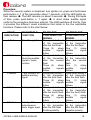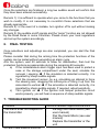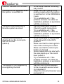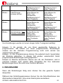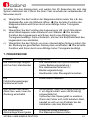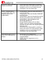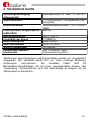
1
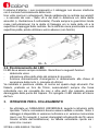
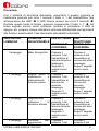
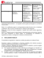
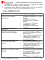
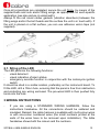
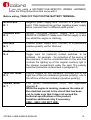
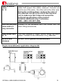
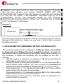
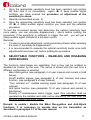
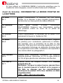
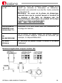
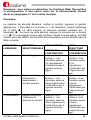
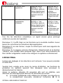
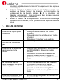
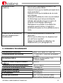
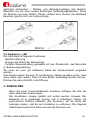
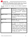
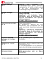
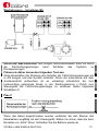
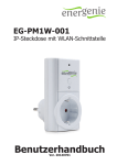
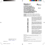
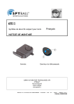
®
SPYBALL 6808-9/6828-9
MANUALE INSTALLAZIONE
FITTING INSTRUCTIONS
NOTICE DE POSE
EINBAUANLEITUNG
VEHICLE SECURITY
Questo manuale contiene le informazioni occorrenti per installare il
sistema di sicurezza e configurarlo come richiesto dal cliente e/o dalle
disposizioni normative locali. Per informazioni dettagliate sul
funzionamento, Vi invitiamo a consultare il manuale di utilizzo.
Sommario
1.
2.
2.1.
2.2.
3.
4.
5.
6.
7.
8.
1.
Contenuto del kit
Posizionamento della centrale e del LED
Posizionamento della centrale
Posizionamento del LED
Istruzioni per il collegamento
Regolazione della sensibilità del sensore di spostamento
Funzioni selezionabili – Procedura di abilitazione e
disabilitazione
Collaudo finale
Guida ricerca guasti
Dati Tecnici
CONTENUTO DEL KIT
Il kit comprende
•
Una centrale
•
Uno o due trasmettitori di comando a distanza con funzione Biker
Recognition
•
Un kit accessori di montaggio
•
Manuale di installazione e manuale utente.
2.
POSIZIONAMENTO DELLA CENTRALE E DEL LED
2.1. Posizionamento della centrale
Scegliete una collocazione adeguata, ben nascosta e protetta dal corpo della
moto, lontano da fonti di calore eccessivo e infiltrazioni di acqua.
La centrale può essere posizionata orizzontalmente, verticalmente o
sottosopra; l’orientamento non influenza le prestazioni del sensore di
spostamento. I cavi che escono dalla centrale devono essere diretti verso il
basso o piegati in modo tale che l’acqua non possa infiltrarsi al suo interno
tramite il cablaggio.
SPYBALL 6808-9/6828-9 ITALIANO
2
Il sistema d’allarme, i suoi componenti e il cablaggio non devono interferire
con il normale funzionamento della moto.
Una volta conclusi i collegamenti, fissate saldamente la centrale servendoVi
– a seconda dei casi – delle viti e dei dadi in dotazione e/o delle alette
amovibili (v. illustrazione A sottostante). Ponete sempre le guarnizioni tonde
rosse (anti-vibrazione) tra le alette di fissaggio e/o le teste delle viti e la
superficie di appoggio della centrale. Se la centrale viene posizionata su una
superficie piatta, potete utilizzare velcro adesivo (non fornito).
ILL. A
2.2. Posizionamento del LED
Il LED deve essere sempre installato. Garantisce le seguenti funzioni:
deterrente visivo
indicazione ottica dello stato del sistema di sicurezza
funzione disinserimento d’emergenza in abbinamento alla chiave di
accensione della moto (v. manuale di utilizzo)
Va installato in posizione visibile, di norma sul quadro degli strumenti. Per
fissarlo, praticate un foro da 10mm, assicurandoVi sempre che l’area
retrostante non sia occupata da cavi o altre parti che possano essere
danneggiate dalla punta del trapano. Poi spingete il LED cablato all’interno
del foro.
3.
ISTRUZIONI PER IL COLLEGAMENTO
-
Se utilizzate un CABLAGGIO UNIVERSALE, seguite le istruzioni sotto
riportate. Tutte le connessioni devono essere saldate e isolate. Nota: il
cablaggio è disponibile in versione multicolore e in versione monocolore
(nero) con fili numerati (i numeri stampigliati all’estremità dei fili vanno
rimossi all’atto dell’installazione). La tabella sottostante riporta sia i
colori che i numeri.
SPYBALL 6808-9/6828-9 ITALIANO
3
-
Se utilizzate un CABLAGGIO DEDICATO (cioè specifico per il modello
di moto che intendete proteggere), seguite le istruzioni fornite con il
cablaggio stesso.
Prima di collegare, RIMUOVETE IL POLO POSITIVO DELLA
BATTERIA.
Filo NERO
N. 1
Negativo d’alimentazione. Collegare ad una buona massa.
Nel caso di cablaggi con doppio negativo d’alimentazione,
collegare i due fili a due punti di massa diversi;
Filo
ARANCIO
N. 2
Positivo condizionato dalla chiave quadro (+15/54).
COLLEGARE SEMPRE. Assicurarsi che l’alimentazione
positiva sia presente anche durante la fase di avviamento;
Filo ROSSO
N. 3
Positivo d’alimentazione. Collegare ad
permanente attraverso il fusibile da 10A;
Filo BLU
N. 4
Ingresso d’allarme istantaneo selezionabile (negativo o
positivo) per pulsanti di massa (opzionali) da installare, ad
esempio, a protezione della sella o dei bauletti. Può essere
raccordato anche al filo che comanda l’accensione della
plafoniera sottosella d’origine, per proteggere il vano
portaoggetti. La selezione della polarità avviene come
descritto nel paragrafo 5;
Fili GIALLI
N. 5
Uscite per comando indicatori di direzione (polarità positiva).
Collegare un filo alla linea destra e un filo alla linea sinistra
degli indicatori di direzione;
Fili VERDI
N. 7
Primo circuito immobilizzo motore, vedere schema
applicativo (ill. B).
Nota: misurare a motore acceso che il valore di corrente
dove è stata eseguita l’interruzione non superi le
caratteristiche tecniche del prodotto.
Eventualmente installare un relè supplementare.
6808 – 6809 = NON UTILIZZARE;
SPYBALL 6808-9/6828-9 ITALIANO
un
positivo
4
Fili BIANCO/
VERDE
N. 12
Secondo circuito immobilizzo motore, Interrompere il filo
positivo che alimenta il teleruttore del motorino di
avviamento. Collegare una estremità ad uno dei fili, l’altra
estremità all’ altro filo.
Nota: misurare in fase di avviamento che il valore di
corrente dove è stata eseguita l’interruzione non superi
le caratteristiche tecniche del prodotto.
Eventualmente installare un relè supplementare.
6808 – 6809 = NON UTILIZZARE;
Fili ROSSO e
MARRONE
connettore
2 vie
Collegare il LED cablato fornito nel sacchetto accessori dell’
allarme;
Filo BIANCO/ Questo filo fornisce un segnale trigger negativo durante la
ROSSO
fase di allarme. Consente, per es., il collegamento di
N. 13
BikerSat;
Filo NERO Antenna
ATTENZIONE non deve MAI essere tagliata né messa a
massa!
Schema applicativo immobilizzo motore (B)
SPYBALL 6808-9/6828-9 ITALIANO
5
NOTA: su alcuni modelli di moto, all’inserimento del sistema di sicurezza si
producono ritorni di corrente dagli indicatori di direzione. EFFETTUATE
SISTEMATICAMENTE IL TEST SEGUENTE: senza accendere il quadro,
portate il deviatore degli indicatori di direzione in posizione ON e inserite il
sistema; se gli strumenti sul cruscotto si accendono, E’ INDISPENSABILE
INSTALLARE IL DIODO IN DOTAZIONE SUL POSITIVO SOTTO CHIAVE
CHE ALIMENTA LA CENTRALE DI COMANDO DEGLI INDICATORI DI
DIREZIONE (v. illustrazione C sottostante)
Schema C
Una volta completati i collegamenti, raccordate accuratamente il connettore
del cablaggio alla centralina (assicuratevi di ottenere il “clic”) e ricollegate il
morsetto di batteria.
4.
REGOLAZIONE DELLA SENSIBILITA’ DEL SENSORE DI
SPOSTAMENTO
Il sensore di spostamento può essere regolato su 8 livelli di sensibilità al
movimento + 8 livelli di sensibilità all’urto.
1.
2.
3.
4.
5.
6.
Con il sistema di sicurezza disinserito, accendere il quadro. Ä Dopo 20
secondi il LED si accende e rimane illuminato per 3 secondi.
Durante questo lasso di 3 secondi, premere il pulsante n. 1 del
trasmettitore. Ä Un segnale sonoro acuto conferma l’ingresso nella
procedura di regolazione della sensibilità al movimento (es. traino /
sollevamento).
Premere il pulsante n. 1 per incrementare la sensibilità. Ä Si ottiene un
breve segnale sonoro acuto di conferma.
Premere il pulsante n. 2 per decrementarla. Ä Si ottiene un breve
segnale sonoro grave di conferma.
Il livello minimo e il livello massimo di sensibilità sono confermati da 3
bip consecutivi.
Una volta selezionato il livello appropriato, spegnere il quadro e
riaccenderlo immediatamente. Ä Un lungo segnale sonoro grave
SPYBALL 6808-9/6828-9 ITALIANO
6
7.
8.
conferma l’ingresso nella procedura di regolazione della sensibilità
all’urto.
Operare come descritto al punto 3).
Una volta selezionato il livello appropriato, spegnere il quadro. Ä Un
segnale sonoro acuto conferma l’uscita dalla procedura.
Per testare il rilevatore di spostamento e individuare più agevolmente il livello
di sensibilità ottimale, potete simulare il movimento / l’urto prima di uscire
dalla procedura; se la sensibilità è sufficiente per generare un impulso
d’allarme, otterrete un segnale sonoro acuto (in sostituzione del ciclo di
allarme completo).
Note:
•
Per ottenere una regolazione accurata, evitate di simulare urti durante
la selezione della sensibilità al movimento.
•
Consigliamo di valutare i livelli di sensibilità ottimali una volta
completate entrambe le regolazioni, prima di uscire dalla procedura.
5.
FUNZIONI
SELEZIONABILI
–
ABILITAZIONE E DISABILITAZIONE
PROCEDURA
DI
Le funzioni sotto elencate sono selezionabili, cioè possono essere abilitate o
disabilitate a piacimento dell’utilizzatore. La selezione rimane in memoria fino
alla riconfigurazione successiva.
Biker Recognition (v. paragrafo 3 manuale utente e nota in grassetto
sottostante)
Segnalazione acustica on/off (v. paragrafo 4 manuale utente) e
funzione panico (v. paragrafo 9 manuale utente)
Segnalazione acustica indicatore di direzione attivato (v. paragrafo 13
manuale utente)
Funzione anti-aggressione (v. paragrafo 10 manuale utente e nota
sottostante)
Polarità ingresso istantaneo d’allarme (questa selezione è riservata
all’installatore e non deve essere modificata dall’utilizzatore dopo il
montaggio del sistema di sicurezza)
Nota: per abilitare o disabilitare le funzioni Biker Recognition e antiaggressione, occorre agire anche sul telecomando come descritto al
paragrafo 3.1 del manuale utente.
SPYBALL 6808-9/6828-9 ITALIANO
7
Procedura:
Con il sistema di sicurezza disinserito, accendere il quadro, premere e
mantenere premuto per circa 7 secondi il tasto n. 1 del trasmettitore, fino
all’accensione del LED. Ä Il LED rimane acceso per circa 3 secondi. Ä
Durante questo lasso di tempo, premere nuovamente il tasto n. 1. Ä Un
breve segnale sonoro acuto conferma l’entrata in procedura. Il LED si
spegne, poi propone cinque indicazioni luminose differenziate corrispondenti
alle funzioni selezionabili. Fate riferimento alla tabella sottostante:
INDICAZIONE
LUMINOSA
FUNZIONE
PER ATTIVARE
SELEZIONABILE
SEGNALE DI
CONFERMA
PER
DISATTIVARE
SEGNALE DI
CONFERMA
1 lampeggio
Biker Recognition
Premere il
pulsante 2 del
trasmettitore al
termine del primo
lampeggio
Segue 1 segnale
sonoro acuto
2 lampeggi
Segnali sonori di
inserimento
e
disinserimento
+
funzione panico
3 lampeggi
Segnalazione
indicatore
di
direzione attivato
4 lampeggi
Funzione
aggressione
SPYBALL 6808-9/6828-9 ITALIANO
anti-
Premere il
pulsante 1 del
trasmettitore al
termine del primo
lampeggio
Seguono 3
segnali sonori
acuti
Premere il
pulsante 1 del
trasmettitore al
termine del
secondo
lampeggio
Seguono 3
segnali sonori
acuti
Premere il
pulsante 1 del
trasmettitore al
termine del terzo
lampeggio
Seguono 3
segnali sonori
acuti
Premere il
pulsante 1 del
Premere il
pulsante 2 del
trasmettitore al
termine del
secondo
lampeggio
Segue 1 segnale
sonoro acuto
Premere il
pulsante 2 del
trasmettitore al
termine del terzo
lampeggio
Segue 1 segnale
sonoro acuto
Premere il
pulsante 2 del
8
5 lampeggi
trasmettitore al
termine del quarto
lampeggio
Seguono 3
segnali sonori
acuti
Polarità ingresso Premere il
d’allarme
pulsante 1 del
istantaneo
trasmettitore al
termine del quinto
lampeggio
Seguono 3
segnali sonori
acuti
Polarità positiva
trasmettitore al
termine del quarto
lampeggio
Segue 1 segnale
sonoro acuto
Premere il
pulsante 2 del
trasmettitore al
termine del quinto
lampeggio
Segue 1 segnale
sonoro acuto
Polarità negativa
Al termine delle selezioni, un segnale sonoro grave prolungato ne conferma
il buon esito.
Nota 1): è sufficiente agire in corrispondenza delle funzioni che si desidera
modificare. Non occorre riconfermare le selezioni già adeguate.
Nota 2): in caso di errore, spegnere il quadro per uscire senza apportare
modifiche.
Nota 3): i segnali sonori di inserimento / disinserimento e la funzione “panico”
non sono consentiti in alcuni Paesi. Vi consigliamo di verificare la
legislazione locale e configurare il sistema conformemente.
6.
COLLAUDO FINALE
Completate le regolazioni / selezioni, potete procedere al collaudo finale.
Durante il tempo di inibizione le funzioni protettive del sistema possono
essere testate senza provocare un ciclo d’allarme.
Inserite il sistema, attendete 20 secondi perché si stabilizzi, quindi svolgete
le prove del caso nei 40 secondi restanti:
a) Se l’ingresso istantaneo è stato utilizzato per proteggere un bauletto o il
vano sottosella, simulatene l’apertura. Ä Se la simulazione è rilevata
correttamente, viene segnalata da segnali sonori acuti.
b) Testate il sensore di spostamento, simulando ad esempio la forzatura
del bloccasterzo, il traino, il sollevamento dal cavalletto laterale. Ä Se
SPYBALL 6808-9/6828-9 ITALIANO
9
c)
la simulazione è rilevata correttamente, viene segnalata da segnali
sonori acuti. Se occorre, regolate la sensibilità.
Accendete il quadro. Ä Se la protezione del blocchetto chiave funziona
correttamente, si ottiene una serie di segnali sonori acuti.
7. GUIDA RICERCA GUASTI
Problema
Verifiche/operazioni suggerite
L’allarme non risponde al
trasmettitore
-
Gli indicatori di direzione non
funzionano
Il sistema non va in allarme
quando si accende il quadro
-
Il fusibile dell’allarme salta tutte
le volte che si inserisce il
sistema
-
L’allarme / immobilizzatore è
disinserito, ma la moto non parte (6828-9)
SPYBALL 6808-9/6828-9 ITALIANO
Riallineate i trasmettitori (v. manuale
di utilizzo)
Effettuate la procedura di
inizializzazione (v. manuale di
utilizzo)
Verificate che la batteria del
trasmettitore sia carica
Sostituite il trasmettitore o la
centralina
Il diodo è installato al contrario?
Verificate che quando il quadro è
acceso il filo ARANCIO/N. 2 riceva
un positivo 12V
Provate a sostituire la centralina. Se
il difetto persiste, si tratta di un
problema di installazione o di un
problema della moto
E’ stato installato il diodo?
Verificate le connessioni di massa
Provate a sostituire la centralina. Se
il difetto persiste, si tratta di un
problema di installazione o di un
problema della moto
Verificate che la moto sia in folle
Verificate che l’interruttore RUN/OFF
sia in posizione RUN
Verificate che il fusibile principale
dell’accensione della moto sia
integro
Verificate che la batteria della moto
10
-
-
Il sistema non va in allarme per
spostamento / sollevamento
-
sia carica
Alcuni modelli di moto si avviano
soltanto con il cavalletto laterale
sollevato, oppure con la leva della
frizione tirata
Provate a sostituire la centralina. Se
il difetto persiste, si tratta di un
problema di installazione o di un
problema della moto
E’ trascorso il tempo di inibizione?
Il sensore di spostamento è attivato
(non escluso)?
Regolate il sensore di spostamento
(v. paragrafo 4)
8. DATI TECNICI
Alimentazione (centrale)
Consumo di corrente
Nom. 12V Max 17V Min. 9V
< 1 mA OFF; 1mA ON (LED
incluso)
Autoalimentazione
Batteria ricaricabile 7,2V 170mAh
NiMH
Capacità circuito immobilizzo motore Max 6A
(6828-9)
Temperatura di funzionamento
-20°C / +85°C
Potenza acustica sirena
114dB@1m
Dimensioni centrale
90x67x30mm
Dimensioni trasmettitore
50x37x12,5
Pila trasmettitore
3V CR2032
Vita pila trasmettitore
Min. 12 mesi (con funzione Biker
Recognition sempre attiva)
Illustrazioni, descrizioni e caratteristiche sono fornite solo a titolo indicativo. Il
fabbricante si riserva il diritto di modificarle senza preavviso. Si declina
qualsiasi responsabilità per malfunzionamenti/danni imputabili ad
installazione o utilizzo non conformi alle specifiche fornite. Il sistema ha
esclusivamente funzione dissuasiva contro eventuali furti.
SPYBALL 6808-9/6828-9 ITALIANO
11
This guide provides the information required to fit the security system
and set it up in conformity with the customer’s requirements and / or
with possible local legislative requirements. For more detailed
information, please consult the user instructions.
Table of contents
1.
Kit composition
2.
Siting of the control unit and LED
2.1. Siting of the control unit
2.2. Siting of the LED
3.
Wiring instructions
4.
Adjustment of movement detection sensitivity
5.
Selectable functions – Enabling and disabling procedures
6.
Final testing
7.
Troubleshooting guide
8.
Technical data
1.
KIT COMPOSITION
The kit includes
•
A control unit
•
One or two remote control transmitters with Biker Recognition function
•
A set of fitting accessories
•
Installation and operation manuals.
2. SITING OF THE CONTROL UNIT AND LED
2.1. Siting of the control unit
Choose a suitable location, well hidden and protected by the motorcycle
body, far from sources of excessive heat and water infiltrations.
The alarm unit can be placed horizontally, vertically or upside down, the
movement sensor operates independently of the position the alarm is set in,
therefore the angle of placement does not affect it. The leads exiting the
alarm should point downwards or be bent in such a way that water cannot
seep into the alarm body via the loom.
The alarm system, its components and wiring must not interfere with the
normal operation of the motorcycle.
SPYBALL 6808-9/6828-9 ENGLISH
12
Once all connections are completed, secure the unit firmly, by means of the
supplied bolts and nuts and/or fitting wings, as appropriate for each specific
application (see also picture A underneath).
Always fit the red round rubber gaskets (vibration absorbers) between the
fitting wings and/or the bolt heads and the surface the unit is in touch with). If
the unit is placed on a flat surface, you can use adhesive velcro tape (not
supplied).
ILL. A
2.1. Siting of the LED
The LED performs the following functions:
visual deterrent
visual indication of alarm status
emergency override function in conjunction with the motorcycle ignition
switch.
It should be sited in a visible location, preferably on the instrument board. To
fit the LED, drill a 10mm hole, ensuring that the panel is free from obstruction
and protecting any wiring enclosed. The pre-wired LED is then pushed fully
home into the hole.
3.WIRING INSTRUCTIONS
-
If you are using a STANDARD WIRING HARNESS, follow the
instructions herebelow. All the connections should be soldered and
insulated. Remark: the cable harness is available with multi-colour wires
or with one-colour numbered wires (the small numbers printed at the
ends of the wires have to be removed upon installation). The table
herebelow shows both the colours and the numbers.
SPYBALL 6808-9/6828-9 ENGLISH
13
-
If you are using a MOTORCYCLE-SPECIFIC WIRING HARNESS,
follow the fitting instructions that come with it.
Before wiring, TAKE OFF THE POSITIVE BATTERY TERMINAL.
BLACK wire
N. 1
Negative power supply wire. Connect to a good earth
point. If the harness has got two negative power supply
wires, connect them to different earth points;
ORANGE wire
N. 2
Ignition controlled positive supply wire (+15/54).
ALWAYS CONNECT. Make sure that the supply is also
live whilst the engine is cranking;
RED wire
N. 3
Positive power supply wire. Connect to a permanent
positive polarity via the 10A-fuse;
BLUE wire
N. 4
Instantaneous selectable (negative or positive) alarm
trigger input for (optional) contact switches, to be
installed – for example – for protection of the seat or of
the panniers. It can be connected also to the wire that
controls the lighting up of the original courtesy light in
the storage compartment under the seat. The polarity
selection procedure is described in paragraph 5;
YELLOW wires
N. 5
Control outputs for turn indicators. Connect one to the
right line of the turn indicators (positive polarity), one to
the left line of the turn indicators (positive polarity);
GREEN wires
N. 7
First ignition immobilisation circuit. See application
diagram B.
While the engine is running, measure the value of
the electrical current in the circuit that has been
cut, to make sure that it does not exceed the
technical specifications of the product.
Install an additional relay if necessary.
6808 – 6809 = DO NOT USE;
SPYBALL 6808-9/6828-9 ENGLISH
14
WHITE/GREEN
wires
N. 12
Second ignition immobilisation circuit. Cut the positive
cable that powers the starter solenoid. Connect one
end to one of the wires , the other end to the other wire.
During the cranking phase, measure the value of
the electrical current in the circuit that has been
cut, to make sure that it does not exceed the
technical specifications of the product.
Install an additional relay if necessary.
6808 – 6809 = DO NOT USE;
RED and BROWN
wires with a 2way connector
Connect to the pre-wired LED that comes with the
alarm fitting accessories;
WHITE/RED wire
N. 13
This wire supplies a trigger control during the alarm
phase. It allows for the connection of e.g. BikerSat;
BLACK wire
Antenna
Do NOT cut or ground the antenna wire!
Engine immobilisation application diagram (B)
SPYBALL 6808-9/6828-9 ENGLISH
15
REMARK : with some models of bikes, you might experience backfeeds
from the turn indicators upon arming. ALWAYS CARRY OUT THE
FOLLOWING TEST: without turning the ignition on, switch the turn indicators
on and arm the system; if the dashboard instruments light up, IT IS
NECESSARY TO FIT THE SUPPLIED DIODE TO THE IGNITION
CONTROLLED POSITIVE SUPPLY WIRE THAT POWERS THE FLASHER
UNIT (see diagram C herebelow).
Diagram C
Once the wiring has been completed, carefully connect the plug of the wiring
harness to the control unit (make sure you hear a “click”), then re-connect
the battery terminal.
4. ADJUSTMENT OF MOVEMENT DETECTION SENSITIVITY
The movement detector can be adjusted to 8 different levels of sensitivity
to displacement + 8 different levels of sensitivity to shock. Normally it is
fine-tuned for optimal performance by the installer during the final testing, but
the procedure is simple and sensitivity can be modified by the user if
required.
1. While the system is disarmed, turn ignition on. Ä 20 seconds later the
LED lights up and remains on for 3 seconds.
2. During this lapse of time, press push-button n. 1 of the transmitter. Ä A
sharp audible signal confirms you have entered the procedure of
adjustment of the sensitivity to displacement (e.g. towing / lifting).
3. Press push-button n. 1 to increase sensitivity. Ä A short sharp audible
signal confirms the success of the operation.
Press push-button n. 2 to decrease sensitivity. Ä A short deep audible
signal confirms the success of the operation.
The minimum and the maximum sensitivity levels are signalled by 3
audible signals in sequence.
SPYBALL 6808-9/6828-9 ENGLISH
16
4.
Once the appropriate sensitivity level has been selected, turn ignition
off, then turn it on immediately again. Ä A deep audible signal
confirms you have entered the procedure of adjustment of the
sensitivity to shock.
5. Operate as described at pos. 3).
6. Once the appropriate sensitivity level has been selected, turn ignition
off. Ä A sharp audible signal confirms you have quit the selection
procedure.
To test the movement sensor and determine the optimal sensitivity level
more easily, you can simulate displacement / shock before quitting the
procedure; if the sensitivity is sufficient to trigger the unit, you will get a
sharp audible signal (instead of a full alarm cycle).
Remarks:
•
To ensure accurate adjustment, avoid generating shocks while selecting
the level of sensitivity to displacement.
•
It is recommended to evaluate the optimal sensitivity levels once both
adjustments have been set, before quitting the procedure.
5.
SELECTABLE FUNCTIONS – ENABLING AND DISABLING
PROCEDURES
The functions listed below are selectable, that is they can be enabled or
disabled as chosen by the user. The set-up is stored until the next time a
different configuration is selected.
Biker Recognition (see paragraph 3 of user manual and remark in bold
below)
On/off audible signals (see paragraph 4 of user manual) and panic
function (see paragraph 9 of user manual)
“Turn indicator on” audible warning signal (see paragraph 13 of user
manual)
Anti-hijack function (see paragraph 10 of user manual and remark in
bold below)
Polarity of instantaneous alarm trigger input (this selection shall be
operated by the installer and shall not be altered by the user after the
security system has been fitted).
Remark: to enable / disable the Biker Recognition and Anti-Hijack
functions, it is necessary to operate also on the transmitter as
described in paragraph 3.1 of the user manual.
SPYBALL 6808-9/6828-9 ENGLISH
17
Procedure:
While the security system is disarmed, turn ignition on, press and hold down
push-button n. 1 of the transmitter about 7 seconds, until the LED lights up,
then release. Ä The LED remains on about 3 seconds. Ä During this lapse
of time, press push-button n. 1 again. Ä A short sharp audible signal
confirms the procedure has been entered. The LED switches off shortly, then
it provides five different visual indications that relate to the five selectable
functions. Please refer to the chart below:
VISUAL
INDICATION
SELECTABLE
FUNCTION
TO SELECT
CONFIRMATION
SIGNAL
TO DESELECT
CONFIRMATION
SIGNAL
1 flash
Biker Recognition
2 flashes
Arming and
disarming audible
signals + panic
function
3 flashes
“Turn indicator on”
audible warning
signal
4 flashes
Anti-hijack function
5 flashes
Polarity of the
instantaneous
alarm trigger input
Press push-button 1
of the transmitter
after the first flash
Three (3)
sharp
audible
signals
follow
Press push-button 1
of the transmitter
after the second
flash
Three (3)
sharp
audible
signals
follow
Press push-button 1
of the transmitter
after the third flash
Three (3)
sharp
audible
signals
follow
Press push-button 1
of the transmitter
after the fourth flash
Three (3)
sharp
audible
signals
follow
Press push-button 1
of the transmitter
after the fifth flash
Positive polarity
Press push-button 2
of the transmitter
after the first flash
One
(1)
sharp
audible
signal
follows
Press push-button 2
of the transmitter
after the second
flash
One
(1)
sharp
audible
signal
follows
Press push-button 2
of the transmitter
after the third flash
One
(1)
sharp
audible
signal
follows
Press push-button 2
of the transmitter
after the fourth flash
One
(1)
sharp
audible
signal
follows
Press push-button 2
of the transmitter
after the fifth flash
Negative polarity
SPYBALL 6808-9/6828-9 ENGLISH
18
Once the selections are finalised, a long low audible sound will confirm that
they have been entered successfully.
Remark 1): it is sufficient to operate when you come to the functions that you
wish to modify. It is not necessary to re-confirm those selections that are
already appropriate.
Remark 2): in the event of a mistake, turn ignition off to quit without making
any changes.
Remark 3): the audible on/off signals and the “panic” function are not allowed
by the Road Rules in some Countries. Please check your local regulations
and set up the system accordingly.
6.
FINAL TESTING
Once selections and adjustings are also completed, you can start the final
testing.
Please consider that during the arming time the protection functions of the
system can be tested without generating an alarm cycle.
Arm the system, wait 20 seconds to allow for stabilisation, then test the
protection functions as appropriate during the remaining 40 seconds:
a) If the instantaneous alarm trigger input has been used to protect a
case or the storage compartment under the seat, simulate the
removal / opening. Ä If the simulation is detected correctly, it is
signalled by sharp audible signals.
b) Test the movement sensor, by e.g. simulating an attempt to force
the steering lock, dragging the motorcycle or tilting it up from the
side-stand to vertical. Ä If the simulation is detected correctly, it is
signalled by sharp audible signals. If required, adjust sensitivity.
c) Turn ignition on. Ä If the ignition lock tamper protection circuit
works properly, you will hear a sequence of sharp audible signals.
7. TROUBLESHOOTING GUIDE
Problem
The alarm does not respond to
the transmitter
SPYBALL 6808-9/6828-9 ENGLISH
Recommended inspections/actions
Re-align the transmitters (see
user manual)
Pair the transmitters (see user
manual)
Replace the transmitter or the
unit
19
The turn indicators do not work
-
The alarm is not triggered when
the ignition is switched on
-
-
The alarm fuse blows every
time the system is armed
-
The alarm/immobiliser is
disarmed, but the motorcycle
will not not start
(6828-9)
-
The system is not triggered by
moving/lifting the bike
-
SPYBALL 6808-9/6828-9 ENGLISH
Is the diode installed the wrong
way round?
Make sure that there is a 12V
positive supply when the ignition
is switched on to the ORANGE/n.
2 wire
Try a substitute unit. If the
problem remains it is either an
installation problem or a problem
with the motorcycle
Has the diode been installed?
Check the earth connections
Try a substitute unit. If the
problem remains it is either an
installation problem or a problem
with the motorcycle
Is the motorcycle in neutral gear?
Is the kill switch in the RUN
position?
Make sure that the main ignition
fuse in the motorcycle is intact
Make sure that the motorcycle
battery is charged
Some models will only start with
the side stand up or the clutch
lever pulled in
Try a substitute unit. If the
problem remains it is either an
installation problem or a problem
with the motorcycle
Has the arming time elapsed?
Is the movement sensor active
(not disabled)?
Adjust the movement sensor (see
paragraph 4)
20
8.TECHNICAL DATA
Power supply (control unit)
Current consumption rate
Back-up battery
Capacity
of
the
immobilisation circuit
(6828-9)
Operating temperature
Siren sound power
Size of the control unit
Size of the transmitter
Transmitter battery
Transmitter battery life
Nom. 12V Max 17V Min. 8V
< 1 mA OFF; 1mA ON (including the
LED)
Rechargeable 7,2V 170mAh NiMH
battery
engine Max 6A
-20°C / +85°C
114dB@1m
90x67x30mm
50x37x12,5
3V CR2032
Min.
12
months
(with
Recognition function on)
Biker
Diagrams, descriptions and features are only indicative. The manufacturer
reserves the right to modify them without notice. The manufacturer will not be
responsible for malfunctions/damages resulting from the negligence of the
the supplied installation and operation instructions. The system must only be
considered as a deterrent against theft attempts.
SPYBALL 6808-9/6828-9 ENGLISH
21
Ce guide contient les indications nécessaire pour poser le système de
sécurité et le configurer selon la demande du client et/ou les
dispositions locales éventuelles.
Pour connaître les détails du fonctionnement, nous Vous invitons à
consulter la notice d’emploi.
Répertoire
1.
Eléments du kit
2.
Emplacement préconisé
2.1. Emplacement de la centrale
2.2. Emplacement de la LED
3.
Branchement
4.
Réglage de la sensibilité du détecteur de déplacement
5.
Fonctions sélectionnables – procédure de mise en service et
de mise hors service
6.
Essai final
7.
En cas de panne
8.
Données techniques
1.
ELEMENTS DU KIT
Le kit comprend
•
Une centrale
•
Un ou deux émetteurs de commande à distance avec fonction Biker
Recognition
•
Un jeu d’accessoires de montage
•
Les notices de pose et d’emploi.
2.
EMPLACEMENT PRECONISE
2.1. Emplacement de la centrale
Choisissez un endroit approprié, bien caché et protégé par la structure de la
moto, à l’écart des sources de chaleur excessive et des infiltrations d’eau.
L’alarme peut être orientée verticalement ou horizontalement, dans n’importe
quelle position, car cela ne conditionne pas le fonctionnement du détecteur
de déplacement. Les câbles doivent sortir vers le bas ou être pliés de façon
que l’eau ne puisse pas pénétrer dans le boîtier à travers le faisceau. La
SPYBALL 6808-9/6828-9 FRANCAIS
22
centrale, ses composants et le faisceau ne doivent pas interférer avec le
fonctionnement normal de la moto.
Une fois les branchements achevés, assurez la centrale soigneusement, en
utilisant – selon la nécessité - les vis et les écrous livrés et/ou les pattes de
fixation amovibles (v. ill. A ci-dessous). N’oubliez pas les joints ronds rouges
en cautchouc (anti-vibration), à monter entre les pattes et/ou les têtes des vis
et la surface d’appui de la centrale. Si la centrale est placée sur une surface
plate, Vous pouvez utiliser du velcro adhésif (non livré).
ILL. A
2.2. Emplacement de la LED
La LED assure les fonctions suivantes:
dissuasif
affichage de l’état du système de sécurité
fonction désarmement de secours en combinaison avec le contacteur
d’allumage de la moto (v. notice d’emploi)
Elle doit être installée à un endroit visible, d’habitude sur le tableau de bord.
Pour la monter, percez un trou de 10mm (assurez-Vous que derrière il n’ y
ait aucun câble ou élément qui pourrait être endommagé par la perceuse)
puis poussez la LED câblée à l’intérieur du trou.
3.
BRANCHEMENT
-
Si Vous utilisez un FAISCEAU UNIVERSEL, suivez les indications cidessous. Toutes les connexions doivent être soudées et isolées.
Remarque: le faisceau universel est disponible avec fils de couleur et
avec fils noirs numerotés (les numéros estampillés aux bouts des fils
doivent être supprimés lors de l’installation). Le tableau ci-dessous
montre les couleurs et les numéros.
SPYBALL 6808-9/6828-9 FRANCAIS
23
-
Si Vous utilisez un FAISCEAU DEDIE (c’est-à-dire spécifique pour le
modèle de moto à équiper), suivez la notice livrée avec le faisceau.
Avant de brancher, DECONNECTEZ LA BORNE POSITIVE DE
LA BATTERIE.
Fil NOIR
N. 1
Négatif d’alimentation. A raccorder sur une bonne
masse. Si le faisceau a deux négatifs d’alimentation,
les brancher sur deux points de masse différents;
Fil ORANGE
N. 2
Positif
après
contact
(+15/54).
TOUJOURS
RACCORDER. S’assurer que l’alimentation positive
soit présente même au cours de la phase de
démarrage;
Fil ROUGE
N. 3
Positif d’alimentation. A raccorder sur un positif +12V
permanent à travers le fusible de 10A;
Fil BLEU
N. 4
Entrée d’alarme instantanée sélectionnable (négative
ou positive) pour contacteurs (optionnels) à installer,
par exemple, pour la protection de la selle ou des
sacoches. Elle peut être raccordée également sur le fil
qui commande l’allumage du plafonnier d’origine dans
le compartiment sous-selle. La sélection de la polarité a
lieu comme décrit au paragraphe 5;
Fils JAUNES
N. 5
Sorties pour commande indicateurs de direction
(polarité positive). Raccorder un fil à la ligne droite et
un fil à la ligne gauche des indicateurs de direction;
Fils VERTS
N. 7
Premier circuit de coupure moteur. Voir schéma
d’application B.
Remarque : lorsque le moteur tourne, assurez-Vous
que le courant mesuré à l’endroit où la coupure a
été faite ne dépasse pas les caractéristiques
électriques du produit. S’il le faut, installez un relais
supplémentaire.
6808 – 6809 = NE PAS UTILISER ;
SPYBALL 6808-9/6828-9 FRANCAIS
24
Fils BLANC/VERT
n. 12
Deuxième circuit de coupure moteur. Couper le fil
positif qui alimente le télérupteur du démarreur.
Raccorder une extremité à un des fils, l’autre extremité
au deuxième fil.
Remarque : au cours de la phase de démarrage,
assurez-Vous que le courant mesuré à l’endroit où
la coupure a été faite ne dépasse pas les
caractéristiques électriques du produit. S’il le faut,
installez un relais supplémentaire.
6808 – 6809 = NE PAS UTILISER ;
Fils ROUGE et
MARRON avec
connecteur 2 v.
Raccorder à la LED livrée avec les accessoires de
montage de l’alarme ;
Fil
BLANC/ROUGE
Ce fil fournit un signal trigger de polarité négative
durant la phase d’alarme. Il permet de raccorder, par
exemple, un dispositif BikerSat ;
Fil NOIR Antenne
ATTENTION ne jamais couper ni mettre à la masse
l’antenne!
Schéma d’application coupure moteur (B)
SPYBALL 6808-9/6828-9 FRANCAIS
25
REMARQUE: Sur quelques modèles lors de l’armement il se produit des
retours de courant des indicateurs de direction.
EFFECTUEZ
SYSTEMATIQUEMENT L’ESSAI SUIVANT: sans mettre le contact, portez le
déviateur des indicateurs de direction en position ON et armez le système; si
les instruments du tableau de bord s’allument, IL FAUT IMPERATIVEMENT
INSTALLER LA DIODE LIVREE AVEC LA CENTRALE SUR LE POSITIF
APRES CONTACT QUI ALIMENTE LA CENTRALE DE COMMANDE DES
INDICATEURS DE DIRECTION (voir schéma C ci-dessous)
Schéma C
Une fois tous les branchements achevés, raccordez soigneusement le
connecteur du faisceau à la centrale (assurez-Vous d’entendre le déclic) et
rebranchez la borne de la batterie.
4. REGLAGE DE LA SENSIBILITE DU DETECTEUR DE
DEPLACEMENT
Le détecteur de déplacement peut être réglé sur 8 niveaux de sensibilité
au mouvement + 8 niveaux de sensibilité au choc. En principe la
sensibilité optimale est sélectionnée par l’installateur au cours de l’essai
final, mais le réglage est simple et – s’il le faut – il peut être modifié par
l’utilisateur :
1. Le système de sécurité désarmé, mettez le contact. Ä Au bout de 20
secondes la LED s’allume et demeure allumée pendant 3 secondes.
2. Durant ce delai de 3 secondes, appuyez sur le bouton n. 1 de
l’émetteur. Ä Un signal sonore aigu confirme l’accès à la procédure
de réglage de la sensibilité au mouvement (par exemple remorquage
/ soulèvement).
3. Appuyez sur le bouton n. 1 pour augmenter la sensibilité. Ä Vous
percevrez un signal sonore aigu de confirmation.
Appuyez sur le bouton n. 2 pour réduire la sensibilité. Ä Vous
percevrez un signale sonore grave de confirmation.
SPYBALL 6808-9/6828-9 FRANCAIS
26
4.
5.
6.
Le niveau minimal et le niveau maximal de sensibilité sont confirmés
par trois signaux acoustiques successifs.
Une fois le niveau approprié sélectionné, coupez le contact, puis
rallumez-le immédiatement. Ä Un signal sonore grave confirme
l’accès à la procédure de réglage de la sensibilité au choc.
Procédez comme décrit à la pos. 3).
Une fois le niveau approprié sélectionné, coupez le contact. Ä Un
signal sonore aigu confirme que la procédure de réglage a été quittée.
Per tester le détecteur de déplacement et sélectionner plus aisément le
niveau de sensibilité optimal, Vous pouvez simuler le mouvement / le choc
avant de quitter la procédure ; si la sensibilité est suffisante pour déclencher
l’alarme, Vous aurez un signal sonore aigu au lieu du cycle complet
d’alarme.
Remarques :
•
Pour obtenir un réglage soigneux, évitez de simuler des chocs au cours
de la sélection de la sensibilité au mouvement.
•
Il est recommandé d’évaluer les niveaux de sensibilité optimaux après
avoir complété les deux réglages, avant de quitter la procédure.
5. FONCTIONS SELECTIONNABLES – PROCEDURE DE MISE
EN SERVICE ET DE MISE HORS SERVICE
Les fonctions sous-décrites sont sélectionnables, c’est-à-dire qu’elles
peuvent être activées ou désactivées selon le choix de l’utilisateur. La
sélection demeure mémorisée jusqu’à la reconfiguration suivante.
-
Biker Recognition (voir paragraphe 3 de la notice d’emploi et remarque
ci-dessous)
Signal acoustique d’armement / désarmement (voir paragraphe 4 de la
notice d’emploi) et fonction panique (voir paragraphe 9 de la notice
d’emploi)
Rappel acoustique “indicateur de direction en service” (voir paragraphe
13 de la notice d’emploi)
Fonction anti-agression (voir paragraphe 10 de la notice d’emploi et
remarque ci-dessous)
Polarité entrée instantanée d’alarme (cette sélection est réservée à
l’installateur et ne doit pas être modifiée par l’utilisateur après la pose
du système de sécurité)
SPYBALL 6808-9/6828-9 FRANCAIS
27
Remarque : pour activer ou désactiver les fonctions Biker Recognition
et anti-agression, il faut opérer aussi sur la télécommande comme
décrit au paragraphe 3.1 de la notice d’emploi.
Procédure:
Le système de sécurité désarmé, mettez le contact, appuyez et gardez
appuyé env. 7 secondes sur le bouton n. 1 de l’émetteur, jusqu’à l’allumage
de la LED. Ä La LED s’allume et demeure allumée pendant env. 3
secondes. Ä Au cours de cette période, appuyez à nouveau sur le bouton
n. 1. Ä Un court signal sonore aigu confirme l’accès à la procédure. La LED
s’éteint, puis elle affiche les fonctions sélectionnables comme détaillé dans la
table suivante:
INDICATION
LUMINEUSE
1 clignotement
FONCTION
POUR ACTIVER
SELECTIONNABLE
SIGNAL DE
CONFIRMATION
Biker Recognition
Appuyez sur le
bouton n. 1 de
l’émetteur après le
1er clignotement
Confirmation par 3
signaux sonores
aigus
2 clignotements
Signaux sonores
d’armement /
désarmement +
fonction panique
Appuyez sur le
bouton n. 1 de
l’émetteur après le
2ème clignotement
Confirmation par 3
signaux sonores
aigus
3 clignotements
Rappel acoustique
“indicateur de
direction en service”
Appuyez sur le
bouton n. 1 de
l’émetteur après le
3ème clignotement
Confirmation par 3
signaux sonores
aigus
SPYBALL 6808-9/6828-9 FRANCAIS
POUR
DESACTIVER
SIGNAL DE
CONFIRMATION
Appuyez sur le
bouton n. 2 de
l’émetteur après
le 1er
clignotement
Confirmation par
1 signal sonore
aigu
Appuyez sur le
bouton n. 2 de
l’émetteur après
le 2ème
clignotement
Confirmation par
1 signal sonore
aigu
Appuyez sur le
bouton n. 2 de
l’émetteur après
le 3ème
clignotement
Confirmation par
1 signal sonore
aigu
28
4 clignotements
Fonction antiagression
Appuyez sur le
bouton n. 1 de
l’émetteur après le
4ème clignotement
Confirmation par 3
signaux sonores
aigus
5 clignotements
Polarité entrée
instantanée
d’alarme
Appuyez sur le
bouton n. 1 de
l’émetteur après le
5ème clignotement
Confirmation par 3
signaux sonores
aigus
Polarité positive
Appuyez sur le
bouton n. 2 de
l’émetteur après
le 4ème
clignotement
Confirmation par
1 signal sonore
aigu
Appuyez sur le
bouton n. 2 de
l’émetteur après
le 5ème
clignotement
Confirmation par
1 signal sonore
aigu
Polarité négative
Une fois les sélections complétées, un signal sonore grave prolongé
confirme le succès de l’opération.
Remarque 1): il suffit d’agir sur les fonctions qu’on souhaîte modifier. Aucun
besoin de reconfirmer les sélections déjà appropriées.
Remarque 2): en cas d’erreur, couper le contact pour sortir sans apporter de
modifications.
Remarque 3): le signaux sonores d’armement / désarmement et la fonction
“panique” sont interdits dans quelques Pays. Nous Vous recommandons de
bien vérifier la législation locale et de configurer le système conformément.
6.ESSAI FINAL
Lorsque les réglages et les sélections sont achevés, Vous pouvez procéder
à l’essai final.
Veuillez tenir compte qu’au cours du temps d’inhibition, les fonctions de
protection du système peuvent être essayées sans provoquer le
déclenchement de l’alarme.
Armez le système, attendez 20 secondes afin qu’il se stabilise, puis
effectuez les tests appropriés dans les 40 secondes qui suivent:
a) Si l’entrée instantanée a été utilisée pour protéger une sacoche ou
le compartiment sous-selle, simulez-en l’ouverture. Ä Si la
SPYBALL 6808-9/6828-9 FRANCAIS
29
b)
c)
7.
simulation est détectée correctement, Vous percevrez des signaux
sonores aigus.
Testez le détecteur de déplacement, en simulant par exemple une
tentative de forcer l’antivol de direction, le remorquage, le
soulèvement de la béquille latérale. Ä Si la simulation est
détectée correctement, Vous percevrez des signaux sonores
aigus. S’il le faut, réglez la sensibilité.
Mettez le contact. Ä Si la protection du contacteur d’allumage
fonctionne correctement, Vous percevrez des signaux sonores
aigus.
EN CAS DE PANNE
Panne
L’alarme ne répond pas à
l’émetteur
Les indicateurs de
direction ne fonctionnent
pas
L’alarme ne se déclenche
pas lorsqu’on met le
contact
Inspections/opérations recommandées
Realignez les émetteurs (voir notice
d’emploi)
Reprogrammez les émetteurs (voir notice
d’emploi)
Remplacez l’émetteur ou la centrale
La dïode pourrait être installée à l’envers
-
Le fusible de l’alarme
saute toutes les fois qu’on
arme le système
Assurez-Vous qu’un positif 12V parvienne
au fil ORANGE/n. 2 lorsqu’on met le
contact
Remplacez la centrale. Si le défaut se
présente quand même, il s’agit d’un
problème de pose ou d’un problème de la
moto
-
Est-ce que la dïode a bien été installée?
Vérifiez les connexions de masse
Remplacez la centrale. Si le défaut se
présente quand même, il s’agit d’un
problème de pose ou d’un problème de la
moto
L’alarme/immobiliseur sont désarmés, mais la moto
Est-ce que le changement de vitesses est
au point mort?
SPYBALL 6808-9/6828-9 FRANCAIS
30
ne démarre pas
(6828-9)
-
-
L’alarme ne se déclenche
pas par déplacement /
soulèvement
-
Est-ce que l’interrupteur RUN/OFF se
trouve en position RUN?
Assurez-Vous que le fusible principal de la
moto soit intact
Assurez-Vous que la batterie de la moto
soit chargée
Quelques modèles de moto ne permettent
le démarrage que lorsque la béquille
latérale est relevée et que l’on serre la
poignée d’embrayage (débrayer)
Remplacez la centrale. Si le défaut se
présente quand même, il s’agit d’un
problème de pose ou d’un problème de la
moto
Est-ce que la période d’inhibition est
terminée?
Est-ce que le détecteur de déplacement
est actif (non éjecté)?
Réglez la sensibilité du détecteur de
déplacement (voir paragraphe 4)
8. DONNEES TECHNIQUES
Alimentation (centrale)
Consommation de courant
Autoalimentation
Capacité relais coupure moteur
(6828-9)
Température de fonctionnement
Puissance acoustique sirène
Dimensions centrale
Dimensions émetteur
Pile émetteur
Durée pile émetteur
SPYBALL 6808-9/6828-9 FRANCAIS
Nom. 12V Max 17V Min. 9V
< 1 mA OFF; 1mA ON (y compris
la LED)
Batterie rechargeable 7,2V
170mAh NiMH
Max 6A
-20°C / +85°C
114dB@1m
90x67x30mm
50x37x12,5
3V CR2032
Min. 12 mois (fonction Biker
Recognition toujours active)
31
Les illustrations, les descriptions et les caractéristiques sont fournies
uniquement à titre indicatif. Le fabricant se réserve le droit de les modifier
sans préavis. Le fabricant rejette toute responsabilité en cas de
pannes/dommages imputables à l’installation ou à l’utilisation non conformes
aux spécifications fournies. Le système a uniquement une fonction
dissuasive contre les tentatives de vol.
SPYBALL 6808-9/6828-9 FRANCAIS
32
Dieses Handbuch enthält die Auskünfte, die zum korrekten Einbau des
Alarmsystemes und zur Programmierung der Funktionen gemäß dem
Wunsch des Kundes und / oder gemäß nationalen Richtlinien
notwendig
sind.
Für
ausfürlichere
Information,
ist
die
Gebrauchsanleitung einzusehen.
Inhaltsverzeichnis
1.
Lieferumfang
2.
Einbauort
2.1. Einbauort – Steuergerät
2.2. Einbauort – LED
3.
Anschlüße
4.
Empfindlichkeit des Lagesensors einstellen
5.
Optional programmiebare Funktionen
6.
Endabnahme
7.
Fehlersuche
8.
Technische Daten
1. LIEFERUMFANG
Zum Lieferumfang gehören
•
ein Steuergerät
•
ein bzw. zwei Handsender mit Fahrererkennung
•
ein Satz Montagezubehör
•
Bedienungs- und Montageanleitung.
2. EINBAUORT
2.1. Einbauort – Steuergerät
Wählen Sie einen gut versteckten und geschützten Installationsort unter der
Verkleidung. Der Einbauort muss vor Wärmequellen und Wassereintritt
geschützt sein. Das Gerät kann horizontal, vertikal oder kopfüber eingebaut
werden. Die Ausrichtung der Zentrale hat keine Auswirkungen auf die
Leistungen des Lagesensors. Die aus dem Steuergerät kommenden Kabel
müssen nach unten zeigen oder so gebogen werden, dass kein Wasser
längs der Kabel in das Innere des Steuergerätes eindringen kann. Die
Alarmanlage, ihre Bestandteile und der Kabelsatz dürfen den normalen
Betrieb des Motorrads nicht stören. Nachdem alle Anschlüsse gemacht
wurden, befestigen Sie das Steuergerät sicher mit den zum Lieferumfang
SPYBALL 6808-9/6828-9 DEUTSCH
33
gehörigen Schrauben / Muttern und Befestigungsflügel (bei Bedarf).
Montieren Sie die roten runden Dichtungen (Schwingungsdämpfer). Wenn
die Zentrale auf einer flachen Fläche verbaut wird, können Sie Klettband
benutzen (gehört nicht zum Lieferumfang).
BILD A
2.2. Einbauort – LED
Die LED dient für folgende Funktionen:
- Optische Warnung
- Anzeige des Status der Alarmanlage
- Funktion Notausschaltung gekoppelt mit dem Zündschloß des Motorrads
(s. Bedienungsanleitung).
Sie muss an einer gut sichtbaren Stelle am Armaturenbrett eingebaut
werden.
Zum Einbau bohren Sie eine 10 mm-Bohrung. Stellen sie dabei sicher, dass
keine Kabel oder andere Teile mit dem Bohrer beschädigt werden können.
Drücken Sie dann die LED in die Öffnung.
3. ANSCHLÜßE
-
Wenn Sie einen Universalkabelsatz benutzen, befolgen Sie bitte die
unten stehenden Anweisungen.
Alle Anschlüsse müssen gelötet und isoliert werden. Hinweis: Der
Kabelsatz ist in vielfarbiger Version und in einfarbiger Version mit
nummerierten Drähten erhältlich (Die Nummern, die am Ende der
Leitungen stehen, sind bei der Installation zu entfernen). Die folgende
Tabelle gibt sowohl die Farben als auch die Nummern an.
SPYBALL 6808-9/6828-9 DEUTSCH
34
-
Wenn Sie einen Plug-and-Play Kabelsatz benutzen (d.h. einen, der
spezifisch für das Motorradtyp ist, das Sie schützen wollen), befolgen
Sie die Anweisungen, die mit dem Kabelsatz geliefert werden.
Vor dem Anschluss der Leitungen muss die Batterie abgeklemmt
werden.
SCHWARZE Leitung
Nr. 1
Masseleitung
An eine gute Masse anschließen. Bei
Verkabelungen mit doppelter Masse der
Stromversorgung die beiden Leitungen an
zwei
unterschiedlichen
Massestellen
anschließen.
ORANGE Leitung
Nr. 2
Zündungsleitung (+15/54)
Die
Zündungsleitung
muss
immer
angeschlossen werden. Sicherstellen, dass
das Signal auch während der Anlassphase
vorhanden ist.
ROTE Leitung
Nr. 3
Dauerplus (+30)
Mit einer 10A Sicherung direkt an ein
Dauerplus anschließen.
BLAUE Leitung
Nr. 4
Alarmeingang mit wählbarer Polarität (Plus
oder Minus) für Kontaktschalter (nicht
mitgeliefert).
Diese können zum Beispiel unter dem Sitz
oder im Gepäckkoffer angebracht werden.
Versucht jemand auf diesen Bereich
zuzugreifen, wird ein Alarm ausgelöst. Die
Eingangspolarität kann frei gewählt werden.
So kann auch der Raum unter dem Sitz mit
Hilfe eines positiven Signals, welches bei
Einschalten der Innenleuchte geschaltet
wird, abgesichert werden.
SPYBALL 6808-9/6828-9 DEUTSCH
35
GELBE Leitungen
Nr. 5
Ausgänge
zum
Ansteuern
der
Fahrtrichtungsanzeiger (positiv gesteuert).
Eine Leitung an die rechte und eine Leitung
an
die
linke
Anschlussleitung
der
Fahrtrichtungsanzeiger anschließen.
GRÜNE Leitungen
Nr. 7
Erste Wegfahrsperre. Siehe beiliegenden
Schaltplan (Bild B).
Bemerkung:
mit
laufendem
Motor
sicherstellen, dass die Stromstärke die
maximale Belastbarkeit des Systems
nicht überschreitet.
Bei 6808 – 6809 nicht verwenden!
WEISS/GRÜNE Leitungen
Nr. 12
Zweite Wegfahrsperre.
Die Ansteuerrung (Klemme 50) zum
Anlasserrelais muß unterbrochen und mit
jeweils einem Ende dieser Kabel verbunden
werden.
Bemerkung: während der Anlassphase
sicherstellen, dass die Stromstärke die
maximale Belastbarkeit des Systems
nicht überschreitet.
Bei 6808 – 6809 nicht verwenden!
ROTE und BRAUNE
Leitungen mit 2-poligen
Stecker
An die Verkabelung der mitgelieferten LED
anschließen;
WEISS/ROTE Leitung
Nr. 13
Diese Leitung gibt ein negatives Signal bei
Alarmauslösung aus.
Sie kann beispielsweise für den Anschluss
an eine BikerSat Anlage verwendet werden.
Schwarze Antenne
Nicht abschneiden
anschließen.
SPYBALL 6808-9/6828-9 DEUTSCH
oder
an
Masse
36
Wegfahrsperre – Schaltplan (B)
WICHTIGE EMPFEHLUNG: Bei einigen Motorradmodellen kann es durch
die
Fahrtrichtungsanzeiger
beim
Schärfen
des
Systems
zu
Rückspannungen.
Führen sie daher immer den folgenden Test aus:
Ohne Einschalten der Zündung den Schalter der Fahrtrichtungsanzeiger auf
in AN bringen und das System schärfen. Wenn die Instrumente auf dem
Armaturenbrett aufleuchten ist es unbedingt erforderlich die zum
Lieferumfang gehörende Diode in der Zündungsleitung (+15/54) zum
Steuergerät der Fahrtrichtungsanzeiger zu verbauen (siehe folgenden
Schaltplan C).
Plan C
Wenn alle Kabel angeschlossen wurden verbinden Sie den Stecker des
Kabelsatzes sorgfältig mit dem Steuergerät. Stellen sie sicher, dass sie beim
Einrasten ein „Klick“ hören. Schließen Sie die Batterie wieder an.
SPYBALL 6808-9/6828-9 DEUTSCH
37
4. EMPFINDLICHKEIT DES LAGESENSORS EINSTELLEN
Sie
können
den
Lagesensor
in je
8
Empfindlichkeitsstufen
(Positionsänderung, Erschütterung) einstellen. Die Voreinstellung der
Empfindlichkeit übernimmt Ihr Einbaubetrieb.
Sie können die Einstellung jederzeit selbst ändern:
1.
Schalten Sie die Zündung ein (Alarmsystem muss entschärft sein).
Ä Nach 20 Sekunden leuchtet die LED für 3 Sekunden auf.
2.
Drücken Sie in dieser Zeit die Taste 1 des Handsenders. Ä Ein
hoher Ton bestätigt Ihnen, dass Sie sich nun in der
Programmierebene für die Einstellung der Empfindlichkeit bei
Positionsveränderungen befinden.
3.
Um die Empfindlichkeit zu steigern drücken Sie bitte die Taste 1
des Handsenders. Ä Zur Bestätigung ertönt ein hohes Tonsignal.
Zur Verringerung der Empfindlichkeit drücken Sie bitte die Taste 2
des Handsenders. Ä Zur Bestätigung ertönt ein tiefes Tonsignal.
Haben Sie die geringste bzw. die höchste Empfindlichkeitsstufe
erreicht, wird Ihnen dies durch 3 aufeinander folgende Tonsignale
bestätigt.
4.
Nachdem Sie die Empfindlichkeit für Positionsveränderungen
eingestellt haben, schalten Sie bitte die Zündung aus und danach
sofort wieder ein. Ä Ein tiefer Ton bestätigt Ihnen, dass Sie sich
nun in der Programmierebene für die Einstellung der
Erschütterungsempfindlichkeit befinden.
5.
Gehen Sie wie ab Punkt 3 beschrieben vor.
6.
Nachdem Sie die Erschütterungsempfindlichkeit eingestellt haben,
schalten Sie bitte die Zündung aus. Ä Ein hoher Ton bestätigt
Ihnen das Verlassen der Programmierebene.
Um zu überprüfen, ob Sie den Lagesensor richtig eingestellt haben, können
Sie
die
Empfindlichkeit
bei
Positionsveränderungen
und
die
Erschütterungsempfindlichkeit vor Verlassen der Programmierebene testen.
Haben Sie die Empfindlichkeit richtig eingestellt, gibt die Alarmanlage ein
hohes Tonsignal, statt einem kompletten Alarmzyklus, aus.
Bemerkungen:
•
Simulieren Sie eine Auslösung nicht während der Einstellung, sondern
erst
wenn
Sie
beide
Einstellungen
(Empfindlichkeit
bei
Positionsveränderungen, Erschütterungsempfindlichkeit) vorgenommen
haben.
SPYBALL 6808-9/6828-9 DEUTSCH
38
5. OPTIONAL PROGRAMMIEBARE FUNKTIONEN
Die nachstehend aufgeführten Funktionen können auf Wunsch aktiviert oder
deaktiviert werden. Die Einstellungen sind bis zur nächsten Konfiguration
gespeichert.
Fahrererkennung (siehe Punkt 3 der Bedienungsanleitung und
nachstehende Bemerkung)
Akustische Meldung ein / aus (siehe Punkt 4 der Bedienungsanleitung)
und Panikalarm (siehe Punkt 9 der Bedienungsanleitung),
Erinnerung bei eingeschalteten Fahrtrichtungsanzeigern (siehe Punkt
13 der Bedienungsanleitung)
Anti-HiJack-Funktion (siehe Punkt 10 der Bedienungsanleitung und
nachstehende Bemerkung)
Polarität des Alarmeingangs (die Auswahl der Polarität ist dem
Einbauer vorbehalten und darf nach Einbau des Sicherheitssystems
nicht vom Benutzer geändert werden).
Bemerkung: die Funktionen Fahrererkennung und Anti-HiJack müssen
zusätzlich am Handsender programmiert werden (siehe Punkt 3.1 der
Bedienungsanleitung).
Aktivierung / Deaktivierung der Zusatzfunktionen:
Bitte entschärfen Sie das Alarmsystem und halten Sie die Taste 1 des
Handsenders so lange gedrückt, bis die LED zur Bestätigung aufleuchtet.
Lassen Sie nun die Taste des Handsenders wieder los. Ä Die LED bleibt
etwa 3 Sekunden lang an. Ä Drücken Sie bitte während dieser Zeitspanne
erneut die Taste 1. Ä Die LED erlischt und gibt mit verschiedenen
Blinkfrequenzen die programmierbaren Zusatzfunktionen an. Bitte beachten
Sie die nachstehende Tabelle:
LEUCHTANZEIGE
WÄHLBARE
FUNKTION
1x
Blinken
Fahrererkennung
2x
Blinken
Akustiksignale Einund Ausschalten +
Panikalarm
SPYBALL 6808-9/6828-9 DEUTSCH
ZUR AKTIVIERUNG
BESTÄTIGUNGSSIGNAL
Drücken Sie bitte nach
dem ersten Blinken die
Taste 1 des
Handsenders.
Bestätigung durch 3
hohe Tonsignale.
Drücken Sie nach dem
zweiten Blinken die
Taste 1 des
ZUR SPERRUNG
BESTÄTIGUNGSSIGNAL
Drücken Sie bitte nach
dem ersten Blinken die
Taste 2 des
Handsenders.
Bestätigung durch 1
hohes Tonsignal.
Drücken Sie nach dem
zweiten Blinken die
Taste 2 des
39
3x
Blinken
Anzeige
Fahrtrichtungsanzeiger aktiviert
4x
Blinken
Anti-HiJack-Funktion
5x
Blinken
Polarität des
Alarmeingangs (dem
Einbauer vorbehalten)
Handsenders.
Bestätigung durch 3
hohe Tonsignale.
Drücken Sie nach dem
dritten Blinken die
Taste 1 des
Handsenders.
Bestätigung durch 3
hohe Tonsignale
Drücken Sie nach dem
vierten Blinken die
Taste 1 des
Handsenders.
Bestätigung durch 3
hohe Tonsignale.
Drücken Sie nach dem
fünften Blinken die
Taste 1 des
Handsenders.
Bestätigung durch 3
hohe Tonsignale.
PLUS
Handsenders.
Bestätigung durch 1
hohes Tonsignal.
Drücken Sie nach dem
dritten Blinken die
Taste 2 des
Handsenders.
Bestätigung durch 1
hohes Tonsignal
Drücken Sie nach dem
vierten Blinken die
Taste 2 des
Handsenders.
Bestätigung durch 1
hohes Tonsignal.
Drücken Sie nach dem
fünften Blinken die
Taste 2 des
Handsenders.
Bestätigung durch 1
hohes Tonsignal.
MINUS
Ihre Einstellungen werden mit einem langen tiefen Tonsignale bestätigt.
Hinweis 1): Es genügt, die von Ihnen gewünschte Änderung zu
programmieren. Die bereits von Ihnen programmierten Einstellungen
müssen bei der nächsten Programmierung nicht noch einmal neu
vorgenommen werden.
Hinweis 2): Die Programmierung können Sie jederzeit durch Ausschalten
der Zündung abbrechen. In diesem Fall werden versehentlich falsch
programmierte Einstellungen nicht gespeichert.
Hinweis 4): Manche akustischen Alarme wie z.B. der Panikalarm, sind in
manchen Ländern nicht erlaubt. Bitte überprüfen Sie Ihre nationalen
Bestimmungen bevor Sie solch eine Funktion aktivieren.
6. ENDABNAHME
Wenn alle Einstellungen fertig sind, können Sie das gesamte System
überprüfen.
Während des Schärfungsprozesses können Sie die Schutzfunktionen des
Alarmsystems überprüfen, ohne einen Alarmzyklus auszulösen.
SPYBALL 6808-9/6828-9 DEUTSCH
40
Schärfen Sie das Alarmsystem und warten Sie 20 Sekunden bis sich das
System stabilisiert hat. Führen Sie Ihren Test innerhalb der verbleibenden 40
Sekunden durch:
a)
b)
c)
Überprüfen Sie die Funktion der Klappenkontakte indem Sie z.B. den
Gepäckkoffer oder die Sitzbank öffnen. Ä Die korrekte Funktion der
Klappenkontakte wird Ihnen durch eine Abfolge hoher Tonsignale
bestätigt.
Überprüfen Sie die Funktion des Lagesensors z.B. durch Simulieren
eines Abschleppens oder Abhebens vom Ständer. Ä Die korrekte
Funktion des Lagesensors wird Ihnen durch eine Abfolge hoher
Tonsignale bestätigt. Falls erforderlich, können Sie Empfindlichkeit des
Lagesensors neu einstellen.
Überprüfen Sie den Schutz vor einer unberechtigten Nutzung indem Sie
die Zündung bei geschärftem Alarmsystem einschalten. Ä Die korrekte
Funktion wird Ihnen durch eine Abfolge hoher Tonsignale bestätigt.
7. FEHLERSUCHE
Problem
Die Alarmanlage reagiert
nicht auf den Handsender
Prüfung/Abhilfe
Die Handsender neu synchronisieren
(siehe Bedienungsanleitung )
Die Handsender anlernen (s.
Bedienungsanleitung)
Handsender oder Steuergerät ersetzen
Die
Fahrtrichtungsanzeiger
funktionieren nicht
-
Diode falsch installiert?
Das System löst keinen
Alarm aus, wenn man die
Zündung einschaltet
-
Sicherstellen, dass die Orange Leitung /Nr.
2 ein Signal erhält, wenn die Zündung
eingeschaltet ist
Versuchen das Steuergerät zu ersetzen.
Wenn der Fehler sich nicht beheben lässt,
handelt es sich um ein Problem bei der
Installation oder des Motorrads.
-
Wurde die Diode installiert?
Die Masseanschlüsse prüfen
Die Sicherung der
Alarmanlage brennt jedes
SPYBALL 6808-9/6828-9 DEUTSCH
41
Mal durch, wenn man das
System einschaltet
-
Versuchen das Steuergerät zu ersetzen.
Wenn der Fehler sich nicht beheben lässt,
handelt es sich um ein Problem bei der
Installation oder des Motorrads.
Alarm / Wegfahrsperre
ausgeschaltet, aber das
Zweirad startet nicht
(6828-6829)
-
Sicherstellen, dass sich das Motorrad im
Leerlauf befindet
Sicherstellen, dass der Schalter RUN/OFF
auf RUN steht
Sicherstellen, dass die Hauptsicherung der
Zündung des Motorrads nicht defekt ist
Sicherstellen, dass die Batterie des
Motorrads geladen ist
Einige Modelle lassen sich nur dann
starten, wenn die seitliche Abstellstütze
gehoben ist oder wenn der Kupplungshebel
gezogen wird
Versuchen das Steuergerät zu ersetzen.
Wenn der Fehler sich nicht beheben lässt,
handelt es sich um ein Problem bei der
Installation oder des Motorrads.
-
-
Das System geht nicht in
Alarm durch Bewegung /
Heben
-
SPYBALL 6808-9/6828-9 DEUTSCH
Ist die Hemmzeit abgelaufen?
Ist der Bewegungsmelder aktiviert (nicht
ausgeschaltet)?
Stellen Sie den Lagesensor ein (s.
Abschnitt 4)
42
8. TECHNISCHE DATEN
Spannungsversorgung
(Steuergerät)
Stromverbrauch
Notstrombatterie
Leistung Relais Wegfahrsperre
(6828-6829)
Betriebstemperatur
Lautstärke der Sirene
Maße Steuergerät
Maße Handsender
Batterie Handsender
Lebensdauer Batterie
Handsender
Nennspannung 12V Max 17V Min. 9V
< 1 mA entschärft; 1mA geschärft (LED
inbegriffen)
Wiederaufladbarer Akku 7,2V 170mAh
NiMH
Max 6A
-20°C / +85°C
117dB@1m
90x67x30mm
50x37x12,5mm
3V CR2032
Min. 12 Monate (wenn
Fahrererkennung aktiv )
Abbildungen, Beschreibungen und Eigenschaften werden nur unverbindlich
angegeben. Der Hersteller behält sich vor, ohne vorherige Mitteilung,
Änderungen
vorzunehmen.
Der
Hersteller
haftet
nicht
für
Betriebsstörungen/Schäden, die auf einen unsachgemäßen Einbau oder
Verwendung zurückzuführen sind. Die Alarmanlage ist lediglich als ein
Warnsystem zu betrachten.
SPYBALL 6808-9/6828-9
43
Cobra Automotive Technologies
Via Astico 41 – 21100 VARESE – ITALY
www.cobra-at.com
06DE2948A – 01/09
SPYBALL 6808-9/6828-9
44