1
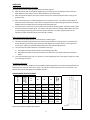
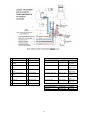
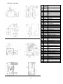
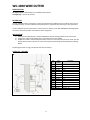
RCS-1000
ROBOTIC
NOZZLE
CLEANING
STATION
WC-1000
WIRE CUTTER
INSTALLATION, OPERATIONS AND REPLACEMENT PARTS MANUAL
0
TABLE OF CONTENTS
INTRODUCTION/WARRANTY .......................................................................................................................................1
RCS-1000 SPECIFICATIONS........................................................................................................................................3
INSTALLATION AND SETUP ..........................................................................................................................................3
OPERATION .............................................................................................................................................................4
REAMER BLADE SELECTION CHART ...............................................................................................................................4
RCS-1000 SCHEMATIC/WIRING DIAGRAM............................................................................................................... 5-6
PART LIST – RCS-1000 .............................................................................................................................................7
WC-1000 WIRE CUTTER SPECIFICATIONS ....................................................................................................................8
WC-1000 DESCRIPTION/INSTALLATION AND PARTS LIST .................................................................................................8
INTRODUCTION
Thank you for purchasing an American Weldquip product. The American Weldquip product you have
purchased has been carefully manufactured, assembled and fully tested. This manual contains information on
the installation, operation, maintenance and replacement part breakdown. Please read, understand and follow
all safety instructions, warnings and procedures. Keep this manual handy for referencing installation,
operation, maintenance and part ordering information. While every precaution has been taken as to the
accuracy in this manual, American Weldquip, Inc. assumes no responsibility for errors or omissions. American
Weldquip, Inc. assumes no liability for damages resulting from the use of the information contained in this
manual. American Weldquip, Inc. shall have no liability to the buyer for consequential damages or expenses by
any defect whatsoever.
WARRANTY
AMERICAN WELDQUIP MIG guns and parts are warranted to be free of defects in material and/or workmanship for the
period of time listed below. For any product found to be defective under normal use, AMERICAN WELDQUIP, INC. at our
option, will repair, replace or issue a credit for the value of the defective product. All warranty claims must be submitted by
the original purchaser. Use of non-genuine AMERICAN WELDQUIP parts and/or consumables may damage and/or severely
limit the performance of the equipment which may limit or void any warranties. AMERICAN WELDQUIP, INC. will not
assume responsibility for incidental damages or expenses related to any defect. This warranty does not cover damage
caused by misuse or abuse, accident, alteration of product, improper installation, misapplication, lack of reasonable care
and maintenance, unauthorized repairs or modifications, loss of use while at a repair facility or other conditions that are
beyond the control of American Weldquip, Inc.
A Return Authorization Number (RA#) must be attained from the factory for any product being returned for Warranty
Repair or Replacement. All returned product must be shipped freight prepaid by the sender. No- charge replacements,
repaired products, or credit will be issued, once the returned product has been evaluated and warranty condition has been
verified. If an immediate replacement is required before proper warranty evaluation, a purchase order number is required
and the goods will be invoiced. A credit will be issued once it is determined that a warranty condition exists.
STANDARD WARRANTY
All Semi-Automatic, Automatic, Robotic MIG TORCHES and Components
MIG Torch Trigger Switches (Contacts only) -Excludes Smoke Extraction
Robotic Nozzle Cleaning Stations, Wire Cutter
Robotic Peripherals, ArcSafe, Gun Mounts
TIG POINT Tungsten Electrode Grinders
= 120 Days
= LIFETIME
= 90 Days
= 90 Days
= 90 Days
LIMITED EXTENDED WARRANTY PROTECTION
This limited extended warranty protection expands coverage to loyal customers who use all GENUINE American Weldquip
1
consumables. Customers filing a claim under the extended warranty will need to prove, by providing past invoices, that
they have been purchasing and using Genuine American Weldquip consumables.
All Semi-Automatic, Automatic, Robotic MIG TORCHES and Components
MIG Torch Trigger Switches (Contacts only) -Excludes Smoke Extraction
MIG Torch Handles
Robotic Nozzle Cleaning Stations, Wire Cutter
Robotic Peripherals, ArcSafe, Gun Mounts
TIG POINT Tungsten Electrode Grinders
= 1 YEAR
= LIFETIME
= LIFETIME
= 90 Days
= 90 Days
= 90 Days
ROHS COMPLIANT
RoHS (Restriction of Hazardous Substances) is an environmental law which addresses the European Union directive
2002/95/EC known as the RoHS Directive. The RoHS directive restricts the use of hazardous substances listed below in
electrical and electronic equipment. While it is not a requirement to meet the directive in the United States, at this time,
American Weldquip Inc. feels this is an important part of our “Go Green initiative. We have taken all reasonable steps to try
to insure the supporting evidence regarding the absence of the restricted substances to support RoHS compliance.
For reference, the maximum concentration values of the restricted substances by weight in homogenous materials are:
Lead/Lead Components
Mercury
Hexavalent Chromium
Polybrominated Biphenyls (PBBs)
Polybrominated Diphenyl Ethers (PBDEs)
Cadmium
- 0.1%
- 0.1%
- 0.1%
- 0.1%
- 0.1%
-0.01%
For RoHS Certification of Compliance Letter on a particular product please visit our website – www.weldquip.com or email
us at [email protected] or call 330-239-0317.
2
RCS-1000 ROBOTIC NOZZLE CLEANING STATION
SPECIFICATIONS
Air Requirements – 80-120 PSI @ 8 S.C.F.M(Min) Clean Shop Air
Reamer Stroke – 2” (50.8mm)
Dimensions – 6 ½”(165.1mm) x 6”(152.4mm) x 12”(304.8mm)
Weight – RCS-1000 - 27Lbs (12.247Kg)
RCS-1000/WC-1000 –31 Lbs. (14.061Kg)
Electrical
(3) Robot Outputs and (1) Robot Input Required
Output: 0VDC Switchable Ground
Output: 24 VDC Continuous Supply
Input: 24 VDC Signal Return
NOTE: RCS-1000 IS SHIPPED FOR “SINKING” LOGIC FROM THE FACTORY
INSTALLATION AND SETUP
Mounting
Mount the nozzle cleaning station in a convenient location within easy access of the robot. Make sure to take into
consideration movable fixtures and other confines within the robotic cell. For proper operation the reamer must be
mounted on a solid, vibration free stand or mount. Mounting dimensions are shown below.
Electrical
WARNING: The following electrical connections should only be performed by a qualified technician. Damage to
equipment will occur if connections are incorrect.
Connection #1 (Brown Lead) – Optional Wire Cutter 0 VDC Cycle Start – connect to a robot output capable of supplying a
timed “GROUND”. This ground pulse determines the length of cutting Time(0.5 Secs.)
Connection #2 (White Lead) - +24VDC Clamp Open Signal – connect to a robot input receiving a +24 VDC signal from the
nozzle cleaning station. This “Cycle Status Signal” informs the robot that the nozzle clamp is open and robot is free to
move.
Connection #3 (Blue Lead) – Continuous 24 VDC – connect to a robot output capable of supply a continuous 24VDC to the
reamer.
Connection #4 (Black Lead) – Reaming 0 VDC Cycle Start – connect to a robot output capable of supplying a timed
“GROUND”. This ground pulse determines the length of reaming time.
Connection #5 (Grey Lead) – Spray 0 VDC Spray Start – connect to a robot output capable of supplying a timed “GROUND”.
This ground determines the length of spray time.
3
Air Supply
The RCS-1000 nozzle cleaning station requires 80-120 psi @ 8 S.C.F.M (5.0-7.0 BAR @ 450 LPM) of clean shop
air minimum for proper operation. The unit is equipped with a ¼” NPT female fitting for the air supply
connection. It is Important to use a supply line with at least 3/8” ID to insure proper air volume to the reamer.
Reamer Tooling
Choose the appropriate size reamer blade for your welding application and welding nozzle I.D. (See page 8 for
available sizes). To remove/install reamer blade use a 14mm wrench to hold the top of the air motor shaft
from turning. Using a 17mm wrench turn reamer blade counter-clockwise to remove or clockwise to install.
Considerable force may be necessary to remove the reamer blade as the blade is designed to self-tighten
during operation.
Nozzle Alignment/Nozzle Clamp Adjustment
CAUTION: Use caution to avoid possible interference with the reamer to the robot torch head or nozzle
components when setting this adjustment. ALWAYS use extreme caution to avoid any pinch or crush point
between the robot and the reamer and/or between the clamping mechanism, torch and the reamer blade.
Failure to heed warnings can results in serious bodily harm.
Correct alignment of the welding nozzle is critical to the proper operation of the RCS-1000.
1) Nozzle OD Adjustment – The clamping V-Block must be adjusted according to the nozzle outside diameter
so as to center the nozzle above the reamer when the clamp is closed. The V-Block is adjusted by turning
the set screw behind the V-Block in or out as shown in Fig 3.
2) Side to Side Alignment – The side to side alignment with respect to reamer is set at the factory and
normally does not require adjustment. If realignment becomes necessary, the entire clamping unit can be
moved from side to side by loosening the (4) button head screws on the top of the unit as shown in Fig 3.
3) Insertion Depth – Insertion depth of the nozzle in relation to the reamer blade is controlled by robot
placement. Depth adjustment should be made by the robot torch operator/programmer. It may be
possible on 5/8 bore nozzles and larger to reamer past the gas holes on the diffuser. This will depend on
the ID of the reamer blade, OD of the diffuser and length of the reamer blade. Normally it is
recommended to only ream the nozzle the length of the contact tip. Use caution when trying to ream past
the length of the contact tip on larger bore nozzles
Anti-Spatter
Anti-Spatter solution is added to the unit by removing the fill cap on top of the bottle. The bottle capacity is
approximately one (1) quart.
4
OPERATION
Robot Programming/Reamer Function
The cycle time for nozzle cleaning is controlled by the robot program.
1) With the ground “ON” on Connection #4(See Fig 2), the clamp secures the welding nozzle in place, the
blade begins to rotate and the reamer spindle shaft starts its upward travel.
2) With the ground still applied, the reamer reaches the top of its stroke and remains there as long as the
ground is “ON”.
3) After the reaming cycle is completed program to turn the ground “OFF”. The reamer will then begin its
downward travel, continuing to rotate with the clamps still closed. Upon reaching the bottom of its stroke
(HOME position), the blade will stop rotating and the clamp will open.
4) Connection #2 is a “Cycle Status” which informs the robot of the clamping status. When the clamp is open
the robot will receive a 24VDC signal. The robot is now able to return to welding. NOTE: When the clamp
is closed during the cleaning cycle Connection #2 will read 0VDC. The robot program should not be
allowed any robot movements when Connection #2 is at 0VDC.
Robot Programming/Spray Function
The cycle time for the Spray function is controlled by the robot program.
1) The robot should be programmed by Connection #5 to spray after the reaming process while held in the
clamp. With the ground “ON” (Fig. 2) the sprayer will dispense anti-spatter solution until the ground is
turned “OFF”. Spray time should be determined by the robot operator/programmer.
2) The amount of anti-spatter delivered is controlled in two ways.
a) The length of time that Connection #5 is activated to ground “ON”.
b) Adjustment of the flow control valve located on the side of the unit directly above the anti-spatter
bottle.
3) Usual recommended spray time is .2 seconds to 1 second depending on the anti-spatter compound. Avoid
over saturating the nozzle.
Feed Rate Adjustment
The feed rate “UP” and/or “DOWN can be controlled by adjusting the flow control valve located inside the unit.
Remove the rear cover for access to the valves. The top valve controls the speed in the “UP” direction. The
bottom valve controls the speed in the “DOWN” direction.
RB625-03
THREAD
TYPE
RB625-02
L2
RB625-01
L1
RB625
ID
RB560
OD
RB500
NOZZLE
BORE SIZE
PART #
REAMER BLADE SELECTION CHART
1/2”
(13mm)
9/16”
(15mm)
5/8”
(16mm)
5/8”
(16mm)
5/8”
(16mm)
5/8”
(16mm)
.490”
(12.5mm)
.555”
(14mm)
.610”
(15.5mm)
.610”
(15.5mm)
.610”
(15.5mm)
.590”
(15mm)
.374”
(9.5mm)
.435”
(11mm)
.511”
(13mm)
.453”
(11.5mm)
.511”
(13mm)
.433”
(11mm)
2.56”
(44.7mm)
2.56”
(65mm)
2.69”
(68mm)
2.56”
(65mm)
2.95”
(75mm)
2.56”
(65mm)
1.76”
(44.7mm)
1.76”
(44.7mm)
2.14”
(54mm)
1.76”
(44.7mm)
2.10”
(54mm)
1.76”
(44.7mm)
Female –
3/8-24
Female –
3/8-24
Female –
3/8-24
Female –
3/8-24
Female –
3/8-24
Female –
3/8-24
Other Reamer Blades Available Upon Request
5
#
1
2
DESCRIPTION
Lift Cylinder
Speed Control Valve –
DOWN
Speed Control Valve –
UP
#
9
10
DESCRIPTION
Pressure Switch
Pneumatic Motor
REAMER FUNCTION
OPERATION SEQUENCE
VALVE ACTION
Ground “OFF” - #4
Valve 11 “ON”
11
Mechanical Valve
Ground “ON” - #4
Valve 4 “ON”
12
Valve Bracket
Hold Ground “ON” - #4
Valve 11 “OFF”
13
Terminal Block
Hold Ground “ON” - #4
Valve 11 “OFF”
6
Solenoid Valve 24VDC Cycle
Solenoid Valve 24VDC –
Spray
Venturi Valve
14
Plug
Ground “OFF” #4
Valve 4 “OFF”
7
Spray Tip
15
Air Supply Lines
Ground “OFF” #4
Valve 11 “ON”
8
Clamp Block Assembly
3
4
5
Torch in SPRAY Position
Torch Away
6
SPRAY FUNCTION
Valve #5 “ON”
Valve #5 “OFF”
CYCLE STATUS
Reamer Off,
Clamp Open
Reamer
Upward Travel
Reamer On,
Clamp Closed
Reamer at Top
of Stroke
Reamer Down
Travel
Reamer “OFF”,
Clamp Open
Sprayer On
Sprayer Off
SCHEMATIC FOR RCS-1000 NOZZLE CLEANING STATION
#
1
2
DESCRIPTION
Lift Cylinder
Speed Control Valve –
DOWN
Speed Control Valve –
UP
#
9
10
DESCRIPTION
Pressure Switch
Pneumatic Motor
REAMER FUNCTION
OPERATION SEQUENCE
VALVE ACTION
Ground “OFF” - #4
Valve 11 “ON”
11
Mechanical Valve
Ground “ON” - #4
Valve 4 “ON”
12
Valve Bracket
Hold Ground “ON” - #4
Valve 11 “OFF”
13
Terminal Block
Hold Ground “ON” - #4
Valve 11 “OFF”
6
Solenoid Valve 24VDC Cycle
Solenoid Valve 24VDC –
Spray
Venturi Valve
14
Plug
Ground “OFF” #4
Valve 4 “OFF”
7
Spray Tip
15
Air Supply Lines
Ground “OFF” #4
Valve 11 “ON”
8
Clamp Block Assembly
3
4
5
Torch in SPRAY Position
Torch Away
7
SPRAY FUNCTION
Valve #5 “ON”
Valve #5 “OFF”
CYCLE STATUS
Reamer Off,
Clamp Open
Reamer
Upward Travel
Reamer On,
Clamp Closed
Reamer at Top
of Stroke
Reamer Down
Travel
Reamer “OFF”,
Clamp Open
Sprayer On
Sprayer Off
PARTS LIST – RCS-1000
Item
#
1
2
3
8
Part
Number
See Blade
Chart
RS-100
RS-101
RS-101NS
4
5
6
7
8
9
10
11
12
13
14
15
16
17
18
19
20
21
22
23
24
25
26
27
28
29
RS-102
RS-103
RS-104
RS-105
RS-106
RS-107
RS-108
RS-109
RS-110
RS-111
RS-112
RS-113
RS-114
RS-115
RS-116
RS-117
RS-118
RS-119
RS-120
RS-121
RS-122
RS-123
RS-124
RS-125
RS-126
RS-127
30
31
32
33
34
35
36
37
38
39
40
RS-128
RS-129
RS-130
RS-131
RS-132
RS-133
RS-134
RS-135
RS-136
RS-137
RS-138
Description
Reamer Blade
Sprayer Tip
Pneumatic Motor, Spray Thru
Pneumatic Motor, Non Spray
Thru
Motor Muffler
Fitting, Elbow ¼” NPT x 1/4” Comp.
Fitting, Elbow 1/8” NPT x 1/4” Comp.
Lift Cylinder
Fitting, Flow Control
Motor Clamp Block
Valve Actuating Bracket
Venturi Valve
Fitting, Elbow 1/8” NPT x 1/8” NPT
Solenoid Valve, Spray
Clamping Cylinder Assembly
V-Block, Clamp Cylinder
Pressure Switch
90⁰ Street Elbow, 1/8” NPT
Street Tee, 1/8” NPT
Fitting, Lateral Tee, 1/8” NPT
Solenoid Valve, Main
Fitting, Male, 10-32 x ¼” Push
Valve Mounting Plate
Terminal Block Holder
Terminal Block
Receptacle – 6-Pin
Connector, ¼” NPT x ¼” Push
Mechanical Valve
Fitting, Male, 1/8” x ¼” Push
Fitting, Elbow 1/8” NPT x ¼”
Push
Bottle Bracket
Bottle – Anti-Spatter
Elbow, ¼” Push x ¼” Push
Unidirectional Valve
Filter – Anti-Spatter
Elbow, 1/8” NPT x ¼” Push
Fitting, Union Tee ¼” Push
Tubing ¼” OD
Guard Plate
Angled Guard Plate
Rear Cover Plate
WC-1000 WIRE CUTTER
SPECIFICATIONS
Air Requirements – 80-120 PSI @ 5 S.C.F.M(Min) Clean Shop Air
Cutting Range – Up TO 1/8” (3.2mm)
DESCRIPTION
The WC-1000 Wire Cutter is designed to remove the ball end of the welding wire for consistent wire stick-out,
providing smoother arc starts and where a desired stick out is required for touch sensing or other operations.
The WC-1000 can be easily mounted to a remote location or directly on the RCS-1000 Robotic Cleaning Station
and can be used with all makes and models of robotic equipment.
INSTALLATION
1) Mount the WC-1000 directly to the RCS-1000 Robotic Nozzle Cleaning Station per the instructions.
2) Program the robot nozzle/welding wire to pass between the cutter blades
3) Program the robot to activate the ground “ON” Lead 4 for a cycle time of 0.5 Seconds. NOTE: This will
activate the wire cutter cylinder to cut the wire without fully activating the RCS-1000 Nozzle Cleaning
Station.
See Wiring Schematic on Page 2 for proper electrical connections.
PARTS LIST – WC-1000
9
Item
#
1
Part
Number
WC-501
Description
2
3
4
5
WC-502
WC-503
WC-504
WC-505
Activator Valve
Cylinder
Screw
6
WC-506
7
8
9
10
11
12
13
14
WC-507
WC-508
WC-509
WC-510
WC-511
WC-512
WC-513
WC-514
Screw
Arm
Shoulder Bolt
Pivot
Stud w/Nut
Bracket
Activator Lever
Cutter Blade
Male Elbow 1/4” NPT x 1/8” NPT
Tee
Tubing, ¼” OD
NOTES:
10
1375 Wolf Creek Trail – P.O. Box 397
Sharon Center, Ohio 44274
330-239-0317 Telephone / 800-949-9353 Fax
11
OM008 – 05/14