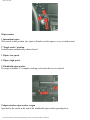
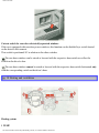
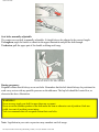
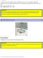
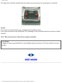
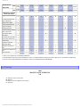
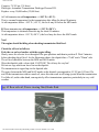
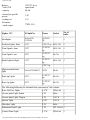
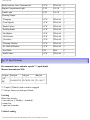
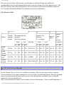
1
1986 Volvo 240
1986
VOLVO
240 DL, 240 GL
Welcome to the world-wide family of Volvo owners. We trust that you will enjoy many years of safe
driving in your Volvo, an automobile designed with your safety and comfort in mind. To ensure your
satisfaction with this vehicle, we encourage you to familiarize yourself with the equipment descriptions,
operating instructions, and maintenance requirements/recommendations in this manual. We also urge
you and your passengers to wear seat belts at all times in this (or any other) automobile. And, of course,
please do not operate a vehicle if you may be affected by alcohol, medication, or any impairment that
could hinder your ability to drive.
Notice:
Your Volvo is designed to meet all applicable safety and emission standards, as evidenced by the
certification labels attached to the door opening sheet metal and on the left wheel housing in the engine
compartment. For further information regarding these regulations, please contact your dealer.
© 1985, VOLVO CARS OF NORTH AMERICA
a Division of Volvo North America Corporation
Contents
DESCRIPTION Page
General Information 2
Keys 3
Instruments and controls 4
Instruments 6
Warning lights 7
Ignition switch, turn signals 8
Lighting 9
Windshield wipers, washer nozzles 10
Washer fluid reservoir 11
Rear window demister, heated seat, hazard warning
12
flasher
Parking brake 13
file:///K|/ownersdocs/1986/1986_240/86240_00.htm (1 of 5)12/30/2006 7:50:07 AM
1986 Volvo 240
Clock, ambient temperature gauge 14
Oil pressure gauge, voltmeter 15
Cigarette lighter, ash trays 16
Electrically operated windows 17
Heating and ventilation 18
Air conditioning 20
Radios, AM-FM-FM stereo/tape players 21
Front seats 22
Seat belts 24
Doors and locks 26
Rear doors, trunk lid, vent windows 27
Hood release, Long load storage 28
Rear/side view mirrors 29
Interior light, sun roof, fuel tank cap 30
Rear seat (wagon) 31
Tailgate (wagon) 32
Cargo compartment (wagon) 33
STARTING AND DRIVING
Service inspection 34
Break-in period 34
Driving economy, shift indicator light 35
Starting the engine 36
Manual transmission 37
Automatic transmission 38
Emergency towing 40
Towing information 41
Trailer hauling 42
Automatic transmission, brake system 43
Catalytic converter 44
MAINTENANCE SERVICE
Maintenance services 45
Service requirements 46
Engine B230F 48
file:///K|/ownersdocs/1986/1986_240/86240_00.htm (2 of 5)12/30/2006 7:50:07 AM
1986 Volvo 240
Engine oil, Oil/oil filter change interval 52
Fuel requirements 50
Engine fluids 51
Cooling system 53
Servicing 56
Transmission oil 60
Rear axle, power steering, brake fluid 62
Lubrication 63
Coolant 64
Alternator, jump starting 65
Replacing bulbs 66
Fuses 71
Wheels and tires 72
Wheel changing 74
Replacing wiper blades 76
Washing, cleaning 76
Cleaning, anti-rust treatment 77
Paint touch-up 78
Long distance trips, cold weather 81
Service diagnosis 82
Specifications 88
Volvo Service Manuals 94
Index 95
All information, illustrations and specifications contained in this manual are based on the latest product
information available at the time of publication. Volvo reserves the right to make model changes at any
time, or to change specifications or design, without notice and without incurring obligation.
pg. 2 General Information
file:///K|/ownersdocs/1986/1986_240/86240_00.htm (3 of 5)12/30/2006 7:50:07 AM
1986 Volvo 240
Do not export your Volvo to another country before investigating that country's applicable safety
and exhaust emission requirements. In some cases it may be difficult or impossible to comply with
these requirements. Modifications to the emission control system(s) may render your Volvo noncertifiable for legal operation in the U.S., Canada and other countries.
pg. 3 Keys
The key number codes are stamped on a separate tag supplied with the keys. This tag should be
file:///K|/ownersdocs/1986/1986_240/86240_00.htm (4 of 5)12/30/2006 7:50:07 AM
1986 Volvo 240
separated from the key ring and kept in a safe place.
The double-sided tape on the back of the tag can be used to secure it safely.
In the event the original keys are lost, duplicates may be ordered from your Volvo dealer.
Top of Page
file:///K|/ownersdocs/1986/1986_240/86240_00.htm (5 of 5)12/30/2006 7:50:07 AM
1986 Volvo 240
1986
VOLVO
240 DL, 240 GL
pg. 4 Instruments and controls
pg. 5 Instruments and controls
See page
1 Air louver 19
2 Turn signals 8
3 Headlights, parking lights 9
4 Instruments, lights 9
5 Instruments 6
file:///K|/ownersdocs/1986/1986_240/86240_01a.htm (1 of 20)12/30/2006 7:50:08 AM
1986 Volvo 240
6 Wiper/washer, tailgate window wiper/ washer (wagon) 10, 11
7 Starting (ignition) switch/steering wheel lock 8
8 Air louver 19
9 Storage compartment (extra instrument or radio location) 10 Air louver 19
11 Glove box 12 Air louver 19
13 Fuse box 65
14 Hood release handle 26
15 Horn 16 Cigarette lighter 14
17 Rear window demister 12
18 Hazard warning flashers 12
19 Air conditioning 18
20 Seat belt reminder light 22
21 Heating and ventilation 16
22 Gear lever or gear selector 35, 36
23 Ash tray 16
24 Fresh air louver 19
25 Radio receptacle 21
26 Fresh air louver 19
27 Electrically-operated windows (240 GL) 17
28 Control for electrically operated side mirrors (certain models only) 29
29 Parking brake 13
30 Electrically-operated window, right front door (240 GL) 17
31 Seat belt release buttons 24
32 Seat heaters 13
33 Seat belt reminder light 24
34 Ash tray 16
The pages in this section provide a detailed description of the vehicle's instruments and controls.
Note that some vehicles may be equipped differently, depending on model, special legal requirements,
etc.
pg. 6 Instruments
file:///K|/ownersdocs/1986/1986_240/86240_01a.htm (2 of 20)12/30/2006 7:50:08 AM
1986 Volvo 240
A Clock or Tachometer (depending on model)
Tachometer reads thousands of engine rpm. Black range for momentary use, during acceleration. Engine
should not be operated in red range.
B Direction indicator (green)
C Speedometer
In kilometers and miles per hour (U.S. models) In kilometers per hour (Canadian models)
D Odometer
Total reading in miles (U.S. models)
Total reading in kilometers (Canadian models)
E Temperature gauge
The gauge pointer should remain inside the black range during normal operation.
If the pointer enters the red range repeatedly, check coolant level and fan belt tension. (See sections
titled "Cooling system and coolant")
WARNING!
allow engine to cool before adding
fluid.
F Fuel gauge
The fuel tank capacity is approx. 60 liters = 15.8 US gals. See "Fuel requirements".
G Alternator warning light (red)
H Oil pressure warning light (red)
file:///K|/ownersdocs/1986/1986_240/86240_01a.htm (3 of 20)12/30/2006 7:50:08 AM
1986 Volvo 240
I Oil pressure warning light (red)
Illuminated when overdrive is engaged.
(manual transmission models)
J Trip odometer reset knob
Push in to reset
K Trip odometer
L High beam indicator (blue)
M Parking brake reminder light (red)
N Brake failure warning light (red)
O Bulb failure warning light
(yellow) (automatic transmission models)
P Overdrive OFF indicator light (yellow)
(automatic transmission models)
Shift indicator light (yellow)
(manual transmission models)
pg. 7 Warning lights
The warning lights described on this page should never be on
when driving
When the ignition is turned on, and before the engine starts, all of the warning lights should be on to test
the function of the bulbs. Should a light not go off after the engine has started, the system indicated
should be inspected. (However, the parking brake reminder light will not go off until the parking brake
is fully released.)
G Alternator warning light (red)
If the light comes on while the engine is running, check the tension of the alternator drive belt as soon as
possible. (See section titled "Cooling system".)
file:///K|/ownersdocs/1986/1986_240/86240_01a.htm (4 of 20)12/30/2006 7:50:08 AM
1986 Volvo 240
NOTE: This warning light is illuminated if the alternator is not charging. However, alternator, parking
brake, brake failure, and bulb failure will be illuminated at the same time due to the design of the
system.
H Oil pressure warning light (red)
If the light comes on during driving, the oil pressure is too low. Stop the engine immediately and check
the engine oil level. See section titled "Engine Oil".
After hard driving, the light will come on occasionally when the engine is idling. This is normal,
provided it goes off when the engine speed is increased.
M Parking brake reminder light (red)
This light will be on when the parking brake (hand brake) is applied. The parking brake lever is situated
between the front seats.
N Brake failure warning light (red)
If the light comes on while driving and the brake pedal can be depressed further than normal, it is an
indication that one of the brake circuits is not functioning. Stop immediately, open engine hood and
check brake fluid level (see section "Brake fluid, power steering").
Reservoir empty: do NOT drive. Tow car to shop for check/repair of brake system. Reservoir not
empty: proceed immediately and with caution to a Volvo dealer for an inspection of the brake system.
O Bulb failure warning light (yellow)
The light will come on if any of the following bulbs are defective:
one of the lower beams
one of the tail tights
one of the brake lights (when the brake pedal is depressed).
See section on "Replacing Bulbs".
pg. 8 Starting (ignition) switch, Turn signals
Starting (ignition) switch/steering wheel lock
file:///K|/ownersdocs/1986/1986_240/86240_01a.htm (5 of 20)12/30/2006 7:50:08 AM
1986 Volvo 240
The steering wheel lock may be under tension when the car is parked. Turn the steering wheel slightly to
free the ignition key.
A chime will sound if the starting key is in the ignition lock and the front door on the driver's side is
open. The chime will also sound if the headlights or parking lights are on when the door is open.
The chime goes off when the front door is closed.
Turn signals
1 Signal lever engaged for normal turns.
Note: A defective turn signal bulb will cause turn signal indicator and remaining signal lights to flash
more rapidly than normal.
2 Lane change position. In maneuvers such as lane changing, the driver can flash the turn signals by
moving the turn signal lever to the first stop and holding it there. The lever will return to the neutral
position when released.
file:///K|/ownersdocs/1986/1986_240/86240_01a.htm (6 of 20)12/30/2006 7:50:08 AM
1986 Volvo 240
3 High and low beam switching (headlights on).
Move the lever towards the steering wheel and release it.
3 Headlight flasher (headlights off).
Move the lever towards the steering wheel. The headlight high beam will be on until the lever is
released.
pg. 9 Lighting
Headlights and position lights
All lights off
Parking lights on
Headlights and parking lights on
Switch from upper to lower beams, and vice versa, by moving the turn signal switch lever on the left
side of the steering column towards the steering wheel. The lights can be used without switching on the
file:///K|/ownersdocs/1986/1986_240/86240_01a.htm (7 of 20)12/30/2006 7:50:08 AM
1986 Volvo 240
starting (ignition) key.
A chime will sound if the headlights or parking lights are on and the front door on the driver's side is
open. The chime will also sound if the starting (ignition) key is in the switch lock when the door is open.
The chime goes off when the driver's door is closed.
If the headlight is in position , all lights will go out when starting (ignition) switch is switched off.
Instrument panel lamps rheostat
Clockwise - brighter
Counterclockwise - dimmer.
pg. 10 Windshield wipers, Tailgate window wiper, Washer nozzles
file:///K|/ownersdocs/1986/1986_240/86240_01a.htm (8 of 20)12/30/2006 7:50:08 AM
1986 Volvo 240
Wiper/washer
1 Intermittent wiper.
With switch in this position, the wipers will make a stroke approx. every seventh second.
2 "Single stroke" position.
Switch returns automatically when released.
3 Wipers, low speed.
4 Wipers, high speed.
5 Windshield wiper/washer.
The wiper will make 2-3 complete stroking cycles after the lever is released.
Tailgate window wiper/washer, wagon
Operated by the switch at the end of the windshield wiper/washer operating lever.
file:///K|/ownersdocs/1986/1986_240/86240_01a.htm (9 of 20)12/30/2006 7:50:08 AM
1986 Volvo 240
1 Tailgate wiper
2 Interval position
With the switch in this position, there is one stroking cycle approx. every fifteen seconds.
3 Tailgate washer
Depress the button to start the-wiper/washer. The wiper will complete 2-3 stroking cycles after the
button is released.
Adjusting washer nozzles
The fluid spray may be adjusted by carefully inserting a needle into the metal nozzle and rotating nozzle
to desired position.
4-8" = 10-20 cm.
12" = 30 cm.
pg. 11 Washer fluid reservoir, Rear fog lights
file:///K|/ownersdocs/1986/1986_240/86240_01a.htm (10 of 20)12/30/2006 7:50:08 AM
1986 Volvo 240
Washer fluid reservoir
The washer fluid reservoir for the windshield and tailgate washer (wagon) is located in the engine
compartment and holds approx. 0.8 US gals = 3.2 liters.
During wintertime, the reservoir should be filled with anti-freeze washer fluid specified in section titled
"Cold weather".
Rear fog lights
The rear fog lights are considerably brighter than the normal tail lights and should be used only when
atmospheric conditions, such as fog, rain, snow, smoke or dust reduce the daytime or night time
visibility of other vehicles to less than 500 ft. (152 meters). (The headlights must be switched on.)
Note that local regulations governing the use of these lights may vary.
pg. 12 Rear window demister, Hazard warning flasher
file:///K|/ownersdocs/1986/1986_240/86240_01a.htm (11 of 20)12/30/2006 7:50:08 AM
1986 Volvo 240
Rear window demister
To operate depress the switch. The indicator lamp in the switch will come on. The system will be
switched off automatically after 10-15 minutes or when the starting (ignition) key is switched off. Do
not place items against the inner surface of the rear window that may damage the printed circuit. Do not
scrape the inner surface of the rear window glass with a hard object or use an abrasive window cleaner,
otherwise damage to the printed circuit will occur.
Hazard warning flasher
The four-way flasher should be used to indicate that the vehicle has become a traffic hazard.
Note: Regulations regarding the use of the hazard warning flasher may vary from state to state.
pg. 13 Parking brake
Parking brake (hand brake)
The lever is situated between the front seats. The brake is applied to the rear wheels.
file:///K|/ownersdocs/1986/1986_240/86240_01a.htm (12 of 20)12/30/2006 7:50:08 AM
1986 Volvo 240
The PARKING BRAKE reminder light on the instrument panel comes on whenever the parking brake
lever is not fully released and the ignition is on.
Always use the parking brake (hand brake) when parked.
In order to obtain the best possible performance of the parking brake, the brake linings should be broken
in. (See section titled "Break-in period").
Seat heaters
The front seats are equipped with electrically-heated backrests and seat cushions. The switches engage
the heating which then is thermostatically controlled. It switches on automatically when the temperature
drops below 60°F (15°C) and switches off at approx. 95°F(35°C).
pg. 14 Clock, Ambient temperature gauge
Quartz crystal clock
To reset the hands, push in the reset knob and turn.
file:///K|/ownersdocs/1986/1986_240/86240_01a.htm (13 of 20)12/30/2006 7:50:08 AM
1986 Volvo 240
Ambient temp. gauge (accessory)
An electronic thermometer that indicates ambient temperature just above the road surface. Warns you of
icy road conditions
pg. 15 Oil pressure gauge, Voltmeter
Oil pressure gauge (accessory)
The oil pressure gauge indicates the pressure of the oil in the lubricating system of the engine. The
pressure is dependent on the speed of the engine, the oil temperature and the viscosity of the oil.
The gauge pointer must not go down to the red field while driving.
Note: While idling with a hot engine the pointer may go into the red field. This is not a cause for
concern providing the pointer rises to the normal driving range again when you increase the engine
speed.
file:///K|/ownersdocs/1986/1986_240/86240_01a.htm (14 of 20)12/30/2006 7:50:08 AM
1986 Volvo 240
Voltmeter (accessory)
The voltmeter indicates the voltage in the electrical system and thereby also the state of the battery.
While the car is being driven the pointer should be within the black field.
Should the pointer point to the upper or lower red field when driving, this may indicate some fault in the
electrical system.
Note: While idling with a hot engine (especially with air conditioning ON), the pointer may indicate low
voltage. This is not a cause for concern provided that the indicated voltage increases when you increase
engine speed.
pg. 16 Cigarette lighter, Ash trays
Cigarette lighter
To operate, depress the knob fully. When the knob automatically releases, the cigarette lighter is ready
for use.
The starting (ignition) switch must be ON for the cigarette lighter to function.
file:///K|/ownersdocs/1986/1986_240/86240_01a.htm (15 of 20)12/30/2006 7:50:08 AM
1986 Volvo 240
Ash trays
To remove the ash trays depress the center spring and remove.
pg.17 Electrically-operated windows
Electrically operated windows (standard on certain models)
The electrically-operated windows are controlled by switches set in the door arm rests. All the windows
can be controlled from the driver's are rest as shown in the above illustration.
The starting (ignition) switch must be ON for the electrically-operated windows to function. The
window is lowered if the rear part of the switch is pressed and raised if the front part of the switch is
pressed.
WARNING!
Remove the starting (ignition) key from the car when children are left alone in the
car.
file:///K|/ownersdocs/1986/1986_240/86240_01a.htm (16 of 20)12/30/2006 7:50:08 AM
1986 Volvo 240
Cut-out switch for rear-door electrically-operated windows
If the car is equipped with rear-door power windows, this function can be disabled by a switch located
on the driver's door armrest.
This switch is positioned 90° in relation to the other switches.
The rear door windows can be raised or lowered with the respective door switch as well as the
switch on the driver's door.
The rear door windows cannot be raised or lowered with the respective door switch but instead only
with the corresponding switch on the driver's door.
pg. 18 Heating and ventilation
Heating system
1 TEMP
file:///K|/ownersdocs/1986/1986_240/86240_01a.htm (17 of 20)12/30/2006 7:50:08 AM
1986 Volvo 240
Left = cool
Right = warm
2
FLOOR
Out = no air to floor
In = full flow of air to front and rear floor
Defrost
3
Out = low volume air flow to defroster
In = full flow
4 REC (recirculation)
To be used only on cars equipped with air conditioning.
Do not use for heating.
Out = full flow of outside air
In = air is recirculated for faster cooling
Blower motor
5
Has 4 speeds and is shut completely off when the knob is turned to the left.
6 Air louvers (dash)
The air flow through the louvers is decreased when the
(2) and/or
7 Fresh air louvers (floor) (except models with air conditioning)
Lever placed forward = louver opens
Lever placed rearward = louver closes
pg. 19 Heating and ventilation
How to . . .
. . . obtain max. heat
1 TEMP >>> WARM
file:///K|/ownersdocs/1986/1986_240/86240_01a.htm (18 of 20)12/30/2006 7:50:08 AM
(3) controls are depressed.
1986 Volvo 240
2
depressed
5 FAN
>>> 3(or 4)
6 All dash louvers halfway open and floor air louver closed.
. . . remove condensation
1 TEMP >>>WARM
3 DEF
depressed
5 FAN
>>> 3 (or 4)
6 All louvers closed as well as the floor fresh air louver.
Always keep front external inlet grille (in front of the windshield) clear of obstructions (snow, ice, etc.).
Maximum defroster action
For maximum defroster capacity at very low ambient temperatures, use the recirculation control (button
depressed).
If not using air conditioning, the recirculation feature should not be used in humid climates and at
temperatures about +23°F (-5°C).
Air louvers - dash
A Closed
B Open
C Directing air flow horizontally
D Directing air flow vertically
file:///K|/ownersdocs/1986/1986_240/86240_01a.htm (19 of 20)12/30/2006 7:50:08 AM
1986 Volvo 240
Fresh air louver (floor)
There is a floor-directed fresh air louver on the driver and passenger sides of the vehicle (driver's side
only on some models). Airflow is controlled by the lever at the center of the louver.
Lever placed forward = louver opens
Lever placed rearward = louver closes
Maximum airflow is obtained with louver fully open and the fan (blower motor) shut completely off.
(The fan forces the air through the dash louvers.)
Contents | Top of Page
file:///K|/ownersdocs/1986/1986_240/86240_01a.htm (20 of 20)12/30/2006 7:50:08 AM
1986 Volvo 240
pg. 20 Air conditioning
Air conditioning (standard on certain models)
How to use the air conditioner:
1
Fan
Position 4 for rapid cooling.
2 AIR COND
Start the air conditioning compressor by turning the control knob clockwise toward MAX.
For rapid cooling, position the knob into the orange range beyond MAX. After desired temperature is
reached re-position the control knob into the blue range.
At cruising speeds, the knob should be kept within the blue range. If it remains in the orange range,
icing may occur resulting in decreased cooling capacity.
3
Recirculation
Push in for rapid cooling and during high humidity conditions.
4 TEMP
When using the air conditioner for cooling, the TEMP control should be set to COOL position, fully left.
Use the AIR COND control to regulate the temperature.
To obtain rapid cooling, all windows must be closed and buttons
and
out. Close the floor fresh
air louvers.
Cool air will then be discharged through the four dash outlets which should be fully open.
Note: For rapid removal of condensation from inside glass surfaces, the air conditioner can be switched
on even when not required for interior cooling. The air conditioner will dehumidify the air inside the
file:///K|/ownersdocs/1986/1986_240/86240_01b.htm (1 of 18)12/30/2006 7:50:09 AM
1986 Volvo 240
vehicle.
Have your Volvo dealer check the system for correct operation yearly. The air conditioning system
should be operated periodically to ensure trouble-free performance year round.
pg. 21 Radios, AM-FM-FM stereo/Tape players
Operating instructions
The optional equipment is available from Volvo Accessories in several different models, each with its
own special features. Operating instructions are contained in the manuals associated with each model.
These manuals are placed in the cars when the equipment is installed by the Dealer.
Your Volvo Dealer will be able to assist you with any questions regarding the operation of this
equipment.
Radio antenna mast
Note: Always lower the antenna mast when entering automatic car wash.
The following information may help to explain differences between car radio reception and radio
reception in the home.
Signal sending
FM waves do not follow the earth's surface and do not bounce against the atmosphere as AM waves do.
Cross modulation
When receiving a weak signal in the vicinity of another, stronger signal, both stations may be received
simultaneously.
Weak reception (fading)
Because of the limited range of FM senders and the way FM waves spread, this problem usually occurs
with FM reception.
Mountains or similar obstacles can sometimes cause disturbances.
pg. 22 Front seats
file:///K|/ownersdocs/1986/1986_240/86240_01b.htm (2 of 18)12/30/2006 7:50:09 AM
1986 Volvo 240
Driver seat height
There are two levers, each with three positions, for adjusting the height of the seat (front and/or back of
cushion).
This allows adjustment of the seat cushion angle for added comfort.
After adjusting the seat check that it is securely latched.
Note! Do not attempt to raise seat height while seated.
Horizontal seat adjustment
Pull control upward, then slide seat forward or rearward to desired position.
Make sure that the seat is properly secured when you release the control.
Note: For your safety, never adjust seat while driving.
Electrically heated front seats
The front seats are electrically heated and thermostatically controlled. The heater switches on
automatically when the temperature drops below 60°F (15°C) and switches off at approx. 95°F (35°C).
The heating may also be disengaged manually using the switches on the parking brake console.
Seat back inclination
Rotate control clockwise to tilt seat back rearward.
Rotate counterclockwise to tilt seat back forward.
Note that body weight must be shifted to allow seat back to move forward or rearward.
file:///K|/ownersdocs/1986/1986_240/86240_01b.htm (3 of 18)12/30/2006 7:50:09 AM
1986 Volvo 240
pg. 23 Passenger seat, Child safety
Passenger seat height
The front passenger seat is retained by four brackets, each with three positions. The positions are the
same as for the driver's seat. However, this adjustment must be accomplished manually, using
appropriate hand tools.
Child safety
Volvo recommends the proper use of restraint systems for all occupants, including children. Remember
that regardless of age and size, a child should always be properly restrained in a car.
Holding a child in your arms is NOT a suitable substitute for a child restraint system. In an accident, a
child held in a person's arms can be crushed between the vehicle's interior and an unrestrained person.
The child could also be injured by striking the interior, or by being ejected from the vehicle during a
sudden maneuver or impact. The same can also happen if the infant or child rides unrestrained on the
seat or in the cargo section of a station wagon. Other occupants should also be properly restrained to
help reduce the chance of injuring or increasing the injury of a child.
In many states and provinces there is legislation governing how and where children should be carried in
a car. Find out the regulations existing in your state or province.
A child restraint system can help protect a child in a vehicle. Here's what to look for when selecting a
child restraint system:
It should have a label certifying that it meets applicable Federal Motor Vehicle Safety Standards
(FMVSS 213-80) - or in Canada, CMVSS 213.
● Make sure the child restraint system is appropriate for the child's height, weight and development the label required by the standard or regulation, or instructions for infant restraints, typically provide this
information.
● In using any child restraint system, we urge you to carefully look over the instructions that are
provided with the restraint. Be sure you understand them and can use the device properly and
safely in this vehicle.
● If your child restraint requires a top tether strap, consult your authorized Volvo dealer for top tether
●
file:///K|/ownersdocs/1986/1986_240/86240_01b.htm (4 of 18)12/30/2006 7:50:09 AM
1986 Volvo 240
anchorage and installation information.
When a child has outgrown the child safety seat (approximately 4-5 years of age, depending on size) you
should use the rear seat with the standard seat belt fastened. The best way to protect the child here is to
place the child on a cushion so that the seat lap belt is as far down on the hips as possible.
A safety cushion for this purpose can be obtained from your Volvo dealer.
pg. 24 Seat belts
Seat belts, retractable
Fasten the seat belts before you drive or ride.
Two lights will be illuminated for 4-8 seconds after the starting (ignition) key is turned to driving
position. One light is located in the instrument cluster and one in the console between the front seats.
A chime will sound at the same time if the driver has not fastened his seat belt. The front and rear
outboard seats are provided with self-retracting inertia-reel belts.
To buckle:
file:///K|/ownersdocs/1986/1986_240/86240_01b.htm (5 of 18)12/30/2006 7:50:09 AM
1986 Volvo 240
Pull the belt out from the retractor far enough to insert the latch plate into the receptacle (buckle for rear
seats), until a distinct snapping sound is heard. The belt should not be twisted or turned.
To unfasten, depress red push-button in receptacle (buckle) and let the belts rewind into their retractors.
Note: The lap belt should sit low and tight under abdomen.
The seat belt retractors are normally "unlocked". The retractors will lock up as follows:
● if belt is pulled out rapidly
● during braking and acceleration
● if the vehicle is leaning excessively
● when driving in turns
Check seat belt mechanism function as follows:
1. Attach the seat belt. Pull rapidly on the strap.
2. CAUTION: Check other traffic before performing this check.
Brake firmly from approximately 30 mph (50 km/h) or turn in a tight circle while pulling on the belt.
In all the above checks you should not be able to pull the belt out.
pg. 25 Seat belts
file:///K|/ownersdocs/1986/1986_240/86240_01b.htm (6 of 18)12/30/2006 7:50:09 AM
1986 Volvo 240
Seat belts, manually adjustable
The center rear seat belt is manually adjustable. It should always be adjusted to the correct length.
To lengthen, angle the buckle as shown in the upper illustration and pull the belt through.
To shorten, pull the upper part of the double webbing until snug.
During pregnancy
Pregnant women should always wear seat belts. Remember that the belt should always be positioned in
such a way as to avoid any possible pressure on the abdomen. The lap belt should be located low, as
shown in the above illustration.
WARNING!
Never use any single seat belt for more than one occupant.
Never wear the shoulder portion of the belt under the arm or otherwise out of position. Such use
could, in event of accident, cause injury.
Volvo recommends that all occupants fasten their seat belts.
Note: Legislation in your state or province may mandate seat belt usage.
file:///K|/ownersdocs/1986/1986_240/86240_01b.htm (7 of 18)12/30/2006 7:50:09 AM
1986 Volvo 240
Maintenance
Check periodically that the anchor bolts are secure and that the belts are in good condition.
Use water and a mild detergent for cleaning.
As the seat belts lose much of their strength when stretched, they should be replaced after
collision, even though they may appear to be undamaged.
Never modify or repair the belt on your own. If repair is required, have the work performed by an
authorized Volvo dealer.
pg. 26 Doors and locks
Unlocking front doors
Both front doors can be unlocked by using the starting (ignition) key. Turning the key 1/4 turn counterclockwise (right door: clockwise) lifts the lock buttons on the window ledge and the door can be opened
by pulling the handle.
To open a door from inside, the lock button must first be pulled up.
In wintertime, if the lock is frozen, be careful not to break the key in the lock. Thaw the ice by heating
the lock or the key. Use an electric heater with blower to prevent paint damage when thawing lock.
Locking doors
Both front doors can be locked by using the key. Turning the key 1/4 turn clockwise (left door) or
counter-clockwise (right door) locks the door.
The lock buttons should not be in the down (locked) position during driving. In case of an
accident, this may hinder rapid access to the occupants of the vehicle.
Central lock
The vehicle is equipped with a central lock system. This means the lock on the driver's door
automatically controls the locks on the other doors (including the trunk on Sedan models and the tailgate
on the wagon model).
It the driver's door is locked or unlocked, the other doors will automatically be locked or unlocked.
file:///K|/ownersdocs/1986/1986_240/86240_01b.htm (8 of 18)12/30/2006 7:50:09 AM
1986 Volvo 240
pg. 27 Child safety lock, Trunk lid/ light
Child safety locks
The buttons are located on the rear door jambs.
A The lock functions normally.
B The door cannot be opened from the inside.
Remember, in the event of an accident, the rear seat passengers cannot open the doors from the
inside with the buttons in position B.
Wagon model contains child safety lock on tailgate. The lock differs from that shown above. See section
titled "Wagon, tailgate".
Trunk lid
The trunk lock is incorporated in the central locking system. This means that you can either lock or
unlock the trunk by means of the driver's door lock.
file:///K|/ownersdocs/1986/1986_240/86240_01b.htm (9 of 18)12/30/2006 7:50:09 AM
1986 Volvo 240
You can also operate the trunk lock directly with the owner's key even if the vehicle is centrally locked.
The trunk lock can also be disconnected from the central locking system by turning the key
counterclockwise as shown above:
The trunk is now always locked.
This option can be used if for example, you lend your car to somebody. If you give only the service key
to the driver it will not be possible to open the trunk.
To reconnect the lock to the central locking system:
Trunk light
A Light always off.
B Light on when trunk lid is open.
file:///K|/ownersdocs/1986/1986_240/86240_01b.htm (10 of 18)12/30/2006 7:50:09 AM
1986 Volvo 240
pg. 28 Hood, Long load storage
To open the hood
Pull the release handle (located under the left side of the dash).
Lift the hood slightly, insert a hand under the center line of the hood and depress the safety catch handle.
Open the hood.
Check that the hood locks properly when closing.
Long load storage (except wagon) A flap in the rear seat makes it possible to carry "long loads" such
as skis, etc.
WARNING!
When braking rapidly the load could be displaced and cause injury to occupants. Sharp edges on the
load should be covered for protection. It is essential that the "load" be secured safely. Use belts
locked around the folded down armrest (see illustration).
file:///K|/ownersdocs/1986/1986_240/86240_01b.htm (11 of 18)12/30/2006 7:50:09 AM
1986 Volvo 240
An optional, specially designed, storage bag should also be used to avoid soiling or tearing the
upholstery. Please note that the flap in the rear seat is intended only for light loads such as skis, wood
etc.
Max. length of load 6 1/2 ft = 2 m.
Max. weight of load 33 lbs = 15 kg.
WARNING!
Take care when loading/unloading the vehicle. Always turn off the engine and apply the parking
brake. Place automatic transmission gear shift selector in position P (Park). This will prevent
accidental movement of the gear shift selector to position D (Drive).
pg. 29 Rear/side view mirrors
Rear view mirror
A Normal position
B Night position, reduces glare from following headlights
WARNING!
Packages placed on the rear window shelf can obscure vision and many become dangerous projectiles
in the event of sudden stop or accident.
file:///K|/ownersdocs/1986/1986_240/86240_01b.htm (12 of 18)12/30/2006 7:50:09 AM
1986 Volvo 240
Side-view mirrors
A Adjustment sideways
B Adjustment up/down
Avoid using ice scrapers made of metal as they can easily scratch the mirror surface.
WARNING!
The mirrors should always be adjusted before
driving.
pg. 30 Interior light, Sunroof, Refueling
Interior light
1 Light always on.
2 Light always off.
3 Light is on when either of the front or rear doors are opened.
file:///K|/ownersdocs/1986/1986_240/86240_01b.htm (13 of 18)12/30/2006 7:50:09 AM
1986 Volvo 240
The wagon model has a slightly different kind of interior lamp housing.
On certain models a time delay device illuminates the interior light for approx. 15 seconds after closing
the driver's door. This facilitates finding starting (ignition) switch, etc., during darkness.
Sunroof (certain models)
The sunroof is operated by a handle located between the sun visors.
Unfold the handle and turn it counter-clockwise to open, clockwise to close.
For safety reasons, the handle should always be folded when driving.
Refueling
The fuel tank cap is located behind the door on the right rear fender. Open cap slowly during hot
weather.
When filling, position the cap in the special bracket on the door.
After filling the tank, install the cap and turn until a "click" is heard.
An optional locking cap is also available.
Refer to section titled "Fuel requirements" for additional information.
pg. 31 Rear seat (wagon)
file:///K|/ownersdocs/1986/1986_240/86240_01b.htm (14 of 18)12/30/2006 7:50:09 AM
1986 Volvo 240
The following pages describe the rear seat, tailgate and cargo compartment on the wagon model.
Folding rear seat
Depress either lever located at the front bottom edge of the rear seat cushion (right or left side). Tilt the
seat towards the front seat.
Note: It may be necessary to move front seat forward or raise the seat backs slightly to allow rear seat to
fold down.
Pull the handle on the rear side of the seat back upwards, and fold the seat back forward and down so
that it lies flat. The rear seat back and cushion are held automatically in their respective positions.
CAUTION
When returning the rear seat to it normal position, make sure the latches are securely locked and
the seat belts are easily accessible for use.
pg. 32 Tailgate (wagon)
file:///K|/ownersdocs/1986/1986_240/86240_01b.htm (15 of 18)12/30/2006 7:50:09 AM
1986 Volvo 240
To open from the outside
Depress the release button located under the tailgate handle.
To open from the inside
Pull out the T-handle located at the bottom of the tailgate.
Safety catch
A The lid cannot be opened from the inside.
file:///K|/ownersdocs/1986/1986_240/86240_01b.htm (16 of 18)12/30/2006 7:50:09 AM
1986 Volvo 240
B The lock functions normally.
pg. 33 Cargo compartment (wagon)
Spare wheel, jack
The spare wheel and jack are stored under the hatch to the left in the cargo compartment.
Loosen the two clips 1/4 turn and lift off the hatch.
CAUTION!
Unless the station wagon is equipped with a cargo compartment seat (Volvo accessory), occupants
should not ride in this section of the car.
Concealed storage space
There are two concealed storage areas under the cargo compartment floor.
Locking floor lid
file:///K|/ownersdocs/1986/1986_240/86240_01b.htm (17 of 18)12/30/2006 7:50:09 AM
1986 Volvo 240
The larger lid is lockable and should be used when increased security for stored articles is desirable.
Eyelets
Six eyelets are provided in the cargo compartment for anchoring cargo.
Four eyelets are shown in the illustration. The remaining two are accessible when the seat back is folded
forward.
Note: The eyelets are not to be used as occupant restraints.
CAUTION!
Luggage or other cargo should not be stowed higher than the seat backs. All items should be secured
in place.
Contents | Top of Page
file:///K|/ownersdocs/1986/1986_240/86240_01b.htm (18 of 18)12/30/2006 7:50:09 AM
1986 Volvo 240
1986
VOLVO
240 DL, 240 GL
pg. 34 Break-in period, Service inspection
STARTING AND DRIVING
A new car should be broken-in!
Manual transmission
During the break-in period do not exceed the following speeds*:
First 600 miles (1,000 km)
1st gear 20 mph (30 km/h)
2nd gear 30 mph (50 km/h)
3rd gear 50 mph (80 km/h)
4th gear 70 mph (110 km/h)1
1) 80 mph (130 km/h) with overdrive engaged. Do not use overdrive below 40 mph (65 km/h)
600-1,200 miles (1,000-2,000 km)
1st gear 25 mph(40 km/h)
2nd gear 40 mph (65 km/h)
3rd gear 60 mph (l00 km/h)
4th gear 80 mph (130 km/h) 2
Avoid driving at low speed in high gear.
2) 90 mph (150 km/h) with overdrive engaged.
* These are the maximum speeds recommended by the factory. Note that legislation in different
countries and states can stipulate other max. speeds than those given here.
Automatic transmission
Refrain from using "kick-down" during the first 1,200 miles (2,000 km) when driving a car equipped
with an automatic transmission.
file:///K|/ownersdocs/1986/1986_240/86240_02.htm (1 of 14)12/30/2006 7:50:10 AM
1986 Volvo 240
Breaking in parking brakes
To obtain best parking brake performance, the brake linings should be broken in.
Stop 5-7 times from 30 mph (50 km/h), transmission in neutral, applying the parking brake with the
release button pressed in during the stop. The force must not lock the rear wheels. If this happens,
release the brake enough to let the wheels rotate. Drive a mile between each stop to cool the brakes.
Check for proper parking brake operation.
Note: The brake lights are not illuminated when applying the parking brake. To warn traffic from behind
it is therefore advisable to depress the brake pedal slightly to illuminate the brake lights.
Service Inspection
To ensure proper operation the car should be taken to a Volvo dealer between the first 600-1,200 miles
(1,000-2,000 km) for a service inspection. The oil in the engine, manual transmission and rear axle will
then be changed. This is very important since the oil rapidly collects impurities during the break-in
period.
pg. 35 Driving economy, Shift indicator light
Economical driving does not necessarily mean driving slowly
Better driving economy may be obtained by thinking ahead, avoiding rapid starts and stops and
adjusting the speed of your vehicle to immediate traffic conditions. Observe the following rules:
Bring the engine to normal operating temperature as soon as possible by driving with a light foot on
the accelerator pedal. A cold engine uses more fuel and is subject to increased wear.
● When possible avoid using the car for driving short distances. This does not allow the engine to reach
normal operating temperature.
● Drive carefully and avoid rapid acceleration and hard braking.
● Do not exceed speed limit.
● Avoid carrying unnecessary items (extra load) in the car.
● Check tire pressures regularly (cold tires).
● Remove snow tires when threat of snow or ice has ended.
● Note that roof racks, ski racks, etc., increase air resistance and thereby fuel consumption.
● Avoid using automatic transmission kick-down feature unless necessary.
●
Other factors which decrease gas mileage are:
● Worn or dirty spark plugs
● Incorrect spark plug gap
● Dirty air filter
● Incorrect valve clearance
● Incorrect idle speed
● Dirty engine oil and clogged oil filter
file:///K|/ownersdocs/1986/1986_240/86240_02.htm (2 of 14)12/30/2006 7:50:10 AM
1986 Volvo 240
Dragging brakes
● Incorrect front end alignment
● Low tire pressure
The above mentioned items and others are checked at the standard 10,000 mile (16,000 km)
maintenance service intervals.
●
Shift indicator light
(manual transmission models only)
The Volvo shift indicator light (S.I.L.) is a device designed to help you get even better gas mileage from
your Volvo car. Studies have shown that the best fuel economy is obtained by shifting gears at low
engine rpm and high relative engine load. The Volvo S.I.L. is calibrated to show you when to shift for
improved mileage without sacrificing smooth acceleration.
Use of the S.I.L. is simple. Shift to next higher gear as soon as the light comes on. You may find after
using the S.I.L. for some time that your natural shifting rhythm will adapt to the S.I.L.'s suggestion.
Some drivers may even shift before the light comes on.
Obviously, there will be times when you need to shift later than the light would indicate (for example,
when climbing hills or trailer towing). Using the light regularly, however, should result in a mileage
improvement of six percent or more, depending on how you normally drive.
Programming instructions for shift indicator
If the current supply to the control unit is cut (battery disconnected), the control unit will have to be reprogrammed as the control unit memory will be erased.
Drive the car in each gear (first gear not necessary) for approximately 8 seconds. The gear change
indicator light will flicker once (0.5 seconds), as each gear is programmed.
Note: Remove foot completely from the clutch pedal after each gear change when programming the
control unit.
pg. 36 Starting the engine
To start the engine;
1 Enter the car and fasten the seat belt.
2 Apply the parking brake if not already set.
3 Place the gear selector lever in neutral (position N or P, automatic transmission).
4 Depress the clutch pedal (manual transmission).
file:///K|/ownersdocs/1986/1986_240/86240_02.htm (3 of 14)12/30/2006 7:50:10 AM
1986 Volvo 240
5 Without touching the accelerator pedal turn the ignition key to starting position. Release the key
as soon as the engine starts.
If the engine does not start at once, depress the accelerator pedal halfway and keep it there until
the engine starts.
Avoid repeated short attempts to start (fuel is injected every time the starter is engaged when engine is
cold).
Allow the starter to operate for a longer time (but not more than 15-20 seconds).
Do not race a cold engine immediately after starting.
Engine warm-up - initial driving procedure
Experience shows that engines in vehicles driven short distances are subject to abnormally rapid wear
because the engine never reaches normal operating temperature.
It is therefore beneficial to reach normal operating temperature as soon as possible by driving with a
light foot on the accelerator pedal.
WARNING!
Always open the garage doors fully before starting the engine inside the garage to ensure adequate
ventilation. The exhaust gases contain carbon monoxide, which is invisible and odorless but very
poisonous.
pg. 37 Manual transmission
4-speed manual + overdrive (5th gear) transmission
Depress the clutch pedal fully when changing gears.
Remove the foot from the clutch pedal after every gear shift.
See "Shift indicator light" section for more information on economical use of the manual transmission.
file:///K|/ownersdocs/1986/1986_240/86240_02.htm (4 of 14)12/30/2006 7:50:10 AM
1986 Volvo 240
Overdrive (5th gear)
The overdrive can be engaged only in 4th gear. Depress the clutch fully when engaging and disengaging.
The green control light "5" on the dashboard illuminates when the overdrive is engaged.
The overdrive is engaged and disengaged by depressing the switch on the top of the gear shift lever.
The overdrive is automatically disengaged when downshifting from 4th gear, but make it a habit to
always disengage the overdrive manually before downshifting.
To improve mileage, it is recommended to use the overdrive as much as possible at speeds above 30
mph (50 km/h).
Reverse gear (R)
The detent collar on the gear shift lever must be lifted prior to engaging reverse gear. This prevents
inadvertent selection of reverse gear
pg. 38 Automatic transmission
file:///K|/ownersdocs/1986/1986_240/86240_02.htm (5 of 14)12/30/2006 7:50:10 AM
1986 Volvo 240
Shift positions
P park
R reverse
N neutral
D drive
2 intermediate
1 low
The gear selector can be moved freely between D and 2. Selections of other positions are obtained by
depressing the selector knob prior to moving the selector.
Depressing the selector knob slightly allows selection of positions N and 1.
Depressing the selector knob fully allows selection of positions R and P. This is also necessary when
initially bringing the selector out of position P.
Depressing the selector knob fully thus permits shifting freely between all positions.
P Park
Use this position when parked with the engine running or stopped.
Never use P while car is in motion.
The transmission is mechanically locked in position P. Also use the parking brake when parking on
grades for added safety.
R Reverse
Never use R while car is moving forward.
N Neutral
Neutral position = no gear is engaged. Use parking brake.
D Drive
D is the normal driving position. Upshift and downshift of the forward gears occurs automatically and is
governed by acceleration and vehicle speed.
2 Intermediate position
Upshift and downshift of first two gears (low and intermediate) occurs automatically.
No upshift to 3rd (top) gear occurs.
file:///K|/ownersdocs/1986/1986_240/86240_02.htm (6 of 14)12/30/2006 7:50:10 AM
1986 Volvo 240
Position 2 may be used to obtain forced downshift to 2nd gear for increased engine braking effect.
Position 2 can also be used...
for relatively slow highway driving.
● for city driving.
● when driving on mountain roads where precise speed control is desirable.
● for passing.
1 Low position
If position 1 is selected when driving at high speeds, 2 is engaged first and 1 when the speed has
dropped to approx. 30 mph (50 km/h).
●
NOTE: No upshift once 1 is engaged.
Use position 1 to select low gear with no upshift. Use for instance, when ascending and descending steep
grades.
NOTE:
● Never select P or R while the car is in motion.
● When standing still and selecting D,2,1 or R the engine must be idling.
● Never downshift to 2 or 1 at speeds above 75 mph(125km/h)*.
*Always observe local speed limits!
pg. 39 Automatic transmission
Disengaging 4th gear
The transmission will engage 4th gear automatically after upshifting through first, second and third gears
unless the disengagement button on the side of the gear selector knob is pushed.
When the button is pushed to disengage 4th gear, the transmission operates as a 3-speed unit. If the
button is pushed while 4th gear is engaged, then a downshift to 3rd gear will occur. The transmission,
then, cannot upshift to 4th gear until the button is pushed again. As a reminder, when 4th gear is
file:///K|/ownersdocs/1986/1986_240/86240_02.htm (7 of 14)12/30/2006 7:50:10 AM
1986 Volvo 240
disengaged, the indicator light ( ) in the instrument panel is illuminated.
Be aware that, if 4th gear is disengaged (reminder light illuminated) when the engine is switched off, the
transmission will revert automatically to 4-speed operation (reminder light not illuminated) when the
engine is restarted.
Disengage 4th gear (reminder light illuminated) when:
* towing a trailer
* driving on hilly roads where precise speed control is desired.
Kick-down
Automatic shift to a lower gear is achieved by depressing the throttle pedal fully and briskly.
An up-shift will be achieved when approaching the top speed for a particular gear or by releasing the
throttle pedal slightly.
Kick-down can be used for maximum acceleration or when passing at highway speeds.
Starting and stopping a car equipped with automatic transmission
1. Fasten the seat belt.
2. Apply the parking brake and the brake pedal firmly to hold the car (to prevent the car from moving
when the gear selector is moved).
3. Select position P or N. (Engine cannot be started in any other position).
4. Start the engine by turning the ignition key (see Section "starting the Engine").
5. Select the desired gear.
6. Release the brakes and accelerate.
To stop the car, release the throttle pedal and apply the brakes.
It is not necessary to move the gear selector as the transmission will downshift automatically.
When idling for extended periods of time, select position N to prevent unnecessary heating of the
transmission.
WARNING!
Always place gear selector in Park and apply parking brake before leaving vehicle. Never leave car
unattended with engine running.
pg. 40 Emergency towing (pulling)
file:///K|/ownersdocs/1986/1986_240/86240_02.htm (8 of 14)12/30/2006 7:50:10 AM
1986 Volvo 240
Precautionary steps to observe when towing
Please check with state and local authorities before attempting this type of towing as vehicles being
towed are subject to regulations regarding maximum towing speed, length and type of towing device,
lighting, etc.
Steering must be unlocked.
● Remember that power brake and power steering assists will not be available when engine is
inoperative. Pedal pressure required is 3-4 times above normal and greater steering effort must be
employed.
● Towing cars equipped with automatic transmission:
-Gear selector in position N. Check transmission oil level (see section titled "Transmission oil").
-Maximum speed: 20 mph (30 km/h).
-Maximum distance with rear wheels on ground: 20 miles (30 km).
●
CARS EQUIPPED WITH AUTOMATIC TRANSMISSION CANNOT BE STARTED BY
PUSHING OR PULLING THE CAR.
Jump starting, see section titled "alternator, jump starting"
pg. 41 Tow-truck information
file:///K|/ownersdocs/1986/1986_240/86240_02.htm (9 of 14)12/30/2006 7:50:10 AM
1986 Volvo 240
pg. 42 Trailer hauling
When preparing for trailer hauling, observe the following:
● Use a trailer hitch which meets Federal Safety Standards for rear end collisions (FMVSS 301-75). For
trailer weights exceeding 2,000 lbs (908 kgs) use only a trailer hitch offered as a Genuine Volvo
Accessory.
● Maximum trailer weight recommended by Volvo is 3,300 lbs (1,500 kg).
However, for cars with automatic transmission, an optional Volvo automatic transmission oil cooler
must be installed when trailer weight exceeds 2,000 lbs (908 kgs). With manual transmission, 5th gear
should not be used while towing. Observe legal requirements of the state in which the vehicles are
registered.
All Volvo models are equipped with energy absorbing shock mounted bumpers. Trailer hitch installation
should not interfere with the proper operation of the bumper system.
file:///K|/ownersdocs/1986/1986_240/86240_02.htm (10 of 14)12/30/2006 7:50:10 AM
1986 Volvo 240
WARNING:
Bumper-attached trailer hitches must not be used on Volvos, nor should safety chains be attached to
the bumper. Trailer hitches attaching to the vehicle rear axle must not be used.
NOTE:
Never connect a trailer's hydraulic brake system directly to the vehicle brake system, nor a trailer's
lighting system directly to the vehicle lighting system. Consult your nearest authorized Volvo dealer for
correct installation.
Trailer hauling does not normally present any particular problems, but take into consideration:
● Recommended hitch tongue load is 110 lbs (50 kgs) for trailer weights below 2,650 lbs (1,200 kgs)
and 143-154 lbs (65-70 kgs) for trailer weights above 2,650 lbs (1,200 kgs). However, it must not
exceed 200 lbs (90 kgs).
● For trailer weights between 2,650-3,300 lbs (1,200-1,500 kgs) a top speed of 50 mph (80 km/h)
should never be exceeded.
● Engine and transmission are subject to increased loads. Therefore, engine coolant temperature should
be closely watched when driving in hot climate or hilly terrain. Use lower gear and turn off air
conditioner if temperature gauge pointer enters the red range.
● Avoid overload and other abusive operation.
● Hauling a trailer affects handling, durability and economy. Trailer air dam (Volvo accessory) will
improve mileage.
● It is necessary to balance trailer brakes with the towing vehicle brakes to provide a safe stop (check
and observe State regulations).
● More frequent vehicle maintenance is required.
● Remove the ball and drawbar assembly when the hitch is not being used.
Note: Refer to section entitled "Automatic transmission" for additional trailer hauling tips.
WARNING!
Do not drive with trunk lid or tailgate
open!
Poisonous exhaust gases may enter via the open trunk lid or tailgate. (This is especially true for wagon
models.)
If the trunk lid or tailgate for any reason must be open, proceed as follows:
● Close the windows.
● Set the heating system controls for floor and defroster to max. and the blower to full speed (4). See
section titled "Heating and Ventilation".
file:///K|/ownersdocs/1986/1986_240/86240_02.htm (11 of 14)12/30/2006 7:50:10 AM
1986 Volvo 240
Handling, roadholding
Vehicle load, tire design and inflation pressure are important for proper handling. Therefore check that
the tires are inflated to the recommended pressure according to the vehicle load.
It is recommended to use tires of the same make and dimensions on all four wheels.
CAUTION!
Do not mix radial ply and bias ply tires as this will adversely alter the vehicle handling
characteristics.
Roof rack
Permanent and removable roof racks are available from Volvo Accessories.
Observe the following points when in use.
● Avoid point loads. Distribute the load evenly.
● Place the heavy cargo at bottom of load.
● Observe that center of gravity and handling are influenced by the load weight.
● Increasing load size increases wind resistance.
● Anchor the cargo correctly with a cord.
● Drive carefully. Avoid rapid starts, heavy cornering and heavy braking.
● Max. roof load is 220 Lbs (100 kg); use a roof rack with a sufficient load rating.
pg. 43 Automatic transmission, Brake system
The following "Special Tips" apply to cars with automatic transmission
● For steep hills and when driving for prolonged periods at low speeds, position 1 should be selected.
Avoid, however, repeated changes since this can cause overheating of the transmission oil. For driving
on mountain roads with long persistent uphill gradients, select position 2.
● When negotiating long, steep, downhill slopes, position 1 should be selected and position 2 for less
severe inclines, in order to obtain the best possible engine braking effect.
● Do not hold the car stationary on an incline by using the accelerator pedal. Instead, engage the
handbrake. This prevents the transmission oil from becoming overheated.
● 4th gear must be disengaged when hauling a trailer!
● If an additional transmission oil cooler is installed you can haul a trailer with the overdrive engaged.
See next "special tip".
● When driving with heavy trailers, it is recommended that an additional oil cooler be installed. This
applies especially when driving under severe conditions e.g. mountain driving or prolonged driving at
high speeds without breaks. The additional oil cooler is available as a genuine Volvo accessory.
Regarding oil change, see section titled "Transmission oil".
Moisture on brake discs and brake pads affects braking.
file:///K|/ownersdocs/1986/1986_240/86240_02.htm (12 of 14)12/30/2006 7:50:10 AM
1986 Volvo 240
Driving in rain and slush or passing through a normal car wash can cause water to collect on the brake
discs and pads. This will cause a delay in braking effect when the pedal is depressed. To avoid such a
delay, when the brakes are needed, depress the pedal occasionally when driving in rain or slush.
This will remove the water from the brakes.
This should also be done after washing or starting in very damp weather.
If the brake power assist does not functionThe power assist to the brakes functions only when the engine is running. When the car is moving
without the engine running the brake pedal pressure required to stop the car is increased 3 - 4 times.
The brake pedal feels stiff and hard.
Disc brake noise: A slight-to-moderate amount of disc brake "squeal" is considered normal.
Air dam (front spoiler)
A non-factory air dam can negatively influence the normal flow of cooling air to the front wheel brakes.
(See section titled "Wheels and Tires").
If one of the brake circuits should malfunction the red warning light will come on
(See section titled "Warning Lights".)
The pedal stroke increases slightly and the pedal feels softer but the pedal pressure required does not
increase noticeably.
If the light comes on while driving and the brake pedal can be depressed further than normal, it is an
indication that one of the brake circuits is not functioning. Stop immediately, open engine hood and
check brake fluid level.
Reservoir empty; do NOT drive. Tow car to shop for check/repair of brake system. Reservoir not
empty: proceed immediately and with caution to a Volvo dealer for an inspection of the brake system.
Severe strain on the brake system.
The brakes will be subject to severe strain when driving in mountains or hilly areas. The speed is usually
low which means that the cooling of the brake is less efficient than when driving on level roads.
To reduce the strain on the brakes it is advisable not to use the brakes excessively.
Instead, shift into a lower gear and let the engine help with the braking. A good rule is to use the same
gear downhill as would be used ascending the same grade. For vehicles with automatic transmission use
position 2, or in some cases, 1.
pg. 44 Catalytic converter
Catalytic Converter Cautions
(all U.S.A. and certain Canadian models)
file:///K|/ownersdocs/1986/1986_240/86240_02.htm (13 of 14)12/30/2006 7:50:10 AM
1986 Volvo 240
Keep your engine properly tuned. Certain engine malfunctions, particularly involving the electrical,
fuel or ignition systems, may cause unusually high converter temperatures. Do not continue to operate
your vehicle if you detect engine misfire, noticeable loss of power or other unusual operating
conditions, such as engine overheating or backfiring. A properly-tuned engine will help in avoiding
malfunctions that could damage the Catalytic Converter.
● Remember that tampering with or unauthorized modifications to the engine or the vehicle may be
illegal and can cause catalyst or exhaust system overheating. This includes:
Altering fuel injection settings or components.
Adjusting ignition timing beyond specified limits.
Altering emission system components or location or removing components.
Repeated use of leaded fuel.
● Do not park your car over combustible materials, such as grass or leaves, which can come into contact
with the hot exhaust system and cause such materials to ignite under certain wind and weather
conditions.
● Excessive starter cranking (in excess of one continuous minute) with an intermittently firing or
flooded engine, can cause catalyst or exhaust system overheating. This also applies to lengthy pushing or
towing of vehicle to start (manual transmissions only). Do not attempt to start a car with automatic
transmission by pushing or towing.
●
NOTE: Unleaded fuel is required for cars with catalytic converter. A label on the instrument
panel and rear fender, near the filler inlet, will remind owners and filling station attendant of this
requirement.
Important! It is unlawful to dispense leaded fuel into any vehicle labeled "unleaded gasoline only".
Contents | Top of Page
file:///K|/ownersdocs/1986/1986_240/86240_02.htm (14 of 14)12/30/2006 7:50:10 AM
1986 Volvo 240
1986
VOLVO
240 DL, 240 GL
pg. 45 Maintenance service
MAINTENANCE
Maintenance services
Your Volvo has passed two major inspections before it was delivered to you, according to Volvo specifications. When driven 600-1,200 miles
(1,000-2,000 km), your car should be brought to the Volvo dealer for a service inspection. Engine, manual transmission and rear axle oils, will be
changed at this time.
Following this inspection, maintenance inspections as outlined in this book should be performed every 5,000 miles (8,000 km).
Engine oil and oil filter changes should be performed every 5,000 miles (8,000 km), or at the time intervals outlined on page 52.
The extended maintenance inspection intervals make it even more advisable to follow this program.
Inspection and service should also be performed any time a malfunction is observed or suspected. It is recommended that receipts for vehicle
emission services be retained in the event questions arise concerning maintenance. See your "Warranty Information and Maintenance Records
Booklets"
Maintenance inspection intervals
Volvo advises you to follow the inspection program at 5,000 mile or 8,000 km intervals which is outlined in the "Warranties and Maintenance
Records Manual". This maintenance program contains inspections and services necessary for the proper functioning of your car over the next
inspection interval.
The maintenance inspections contain several checks which require special instruments and tools and therefore must be performed by a qualified
technician.
To keep your Volvo in top condition, specify time tested and proven Genuine Volvo Parts and Accessories.
THE FEDERAL CLEAN AIR ACT (USA)
The Clean Air Act requires vehicle manufacturers to furnish written instructions to the ultimate purchaser to assure the proper functioning of those
components that control emissions.
The maintenance instructions listed in the "Servicing" section of this Manual represent the minimum maintenance required. These services are not
covered by the warranty. You will be required to pay for labor and material used. Refer to your "Warranties and Maintenance Records Manual" for
further details.
In accordance with Federal Regulations, your Volvo is warranted to meet certain Emission Performance Standards. Refer to your Warranty
Information Manual for detailed information concerning:
●
●
●
Emissions Performance Warranty (USA)
Limited 5-Year/50,000-Mile Emission System Warranty (USA)
5-Year/80,000-Kilometer Emission System Warranty (Canada)
pg. 46 Servicing
1986
MAINTENANCE SCHEDULE
240
A= Adjust (Correct if necessary)
R= Replace
I= Inspect (Correct or Replace if necessary)
L= Lubricate
file:///K|/ownersdocs/1986/1986_240/86240_03a.htm (1 of 10)12/30/2006 7:50:12 AM
1986 Volvo 240
Maintenance
Operation
Miles
6005,000 10,000 15,000 20,000 25,000 30,000 35,000 40,000 45,000 50,000 55,000 60,0003
1,200
(Km)
(1,000(8,000) (16,000) (24,000) (32,000) (40,000) (48,000) (56,000) (64,000) (72,000) (80,000) (88,000) (96,000)
2,000)
EMISSION SYSTEM
MAINTENANCE
Engine oil and Oil filter
1
Cooling System Hoses
and Connections
Engine Drive Belts
Torque Manifold Nuts
Valve Clearance
Timing gear belt2
Vacuum Fittings, Hoses
and Connections
Air Cleaner Filter
Idle RPM
Fuel System Cap, Tank,
Lines and Connections
Spark Plugs
Catalytic Converter
Mounting Bolts
Manual Transmission
Oil
Automatic Transmission
Oil
Rear Axle Oil
R
R
R
R
R
R
R
R
R
R
R
R
R
I
A
A
I
I
I
I
A
R
I
R
R
R
R
I
I
A
R
I
I
I
I
I
I
I
I
I
I
I
I
I
I
I
I
R
I
I
I
R
I
I
I
R
R
I
I
I
I
I
I
I
I
I
I
I
I
1) See section "Engine Oil" for detailed information
2) Not included in emissions systems maintenance, but we recommend that the timing gear belt be replaced every 50,000 miles (80,000 km)
3) For services beyond 60,000 miles (96,000 km), consult your "Maintenance Records Manual".
pg. 47 Servicing
1986
MAINTENANCE SCHEDULE
240
A= Adjust (Correct if necessary)
R= Replace
I= Inspect (Correct or Replace if necessary)
L= Lubricate
file:///K|/ownersdocs/1986/1986_240/86240_03a.htm (2 of 10)12/30/2006 7:50:12 AM
1986 Volvo 240
Maintenance
Operation
Miles
6005,000 10,000 15,000 20,000 25,000 30,000 35,000 40,000 45,000 50,000 55,000 60,000
1,200
(Km)
(1,000(8,000) (16,000) (24,000) (32,000) (40,000) (48,000) (56,000) (64,000) (72,000) (80,000) (88,000) (96,000)
2,000)
MISCELLANEOUS
MAINTENANCE
ENGINE
Engine Coolant
Fuel (Line) Filter
PCV Nipple (Orifice)
Ventilation Hoses
BRAKES
Inspect Brakes. Replace
components as
necessary.
Change Brake Fluid
STEERING
Tire Wear (Align front
end if needed.)
Check power steering
fluid level.
BODY
Trunk, Door and Hood
Hinges and Latches.
R
*
I
R
R
I
I
*
I
I
I
I
I
R
I
I
L
I
I
I
I
I
L
I
R
I
I
L
I
I
I
I
L
I
I
L
I
L
I
I
I
L
* Although not part of emission control warranty service, Volvo suggests the flame guard on B230F engines be cleaned every 20,000 miles
(32,000 km).
pg. 48 Service Engine
The following items should be checked weekly by the owner. (This only takes a few
moments.)
Description on page
Engine oil level
51
Brake fluid
62
Radiator coolant level
64
Tire pressures (all five tires)
72 , 93
Operation of all lights
Horns
Windshield wipers
Level of windshield fluid
The following should also be carried out regular intervals.
Washing
Description on page
76
Polishing
77
Cleaning
77
Rust protection
77
file:///K|/ownersdocs/1986/1986_240/86240_03a.htm (3 of 10)12/30/2006 7:50:12 AM
1986 Volvo 240
Engine B230F
1 Data plate
2 Oil filler cap, engine
3 Oil dipstick, engine
4 Brake fluid reservoir
5 Washer fluid reservoir
6 Expansion tank, coolant
7 Oil reservoir, power steering
8 Battery
9 Fuse engine control
pg. 49 Notes
pg. 50 Fuel requirements
Unleaded Fuel
Each Volvo has a catalytic converter and must use only unleaded gasoline (as specified on the instrument panel and by a label near the filler inlet).
U.S. and Canadian regulations require that pumps delivering unleaded gasoline be labeled "UNLEADED". Only these pumps have nozzles which fit
your car's filler inlet. It is unlawful to dispense leaded fuel into a vehicle labeled "unleaded gasoline only".
Leaded gasoline damages the catalytic converter and the oxygen sensor system. Repeated use of leaded gasoline will lessen the effectiveness of the
emission control system and could result in loss of emission warranty coverage. State and local vehicle inspection programs will make detection of
misfueling easier, possibly resulting in emission test failure for misfueled vehicles.
Octane Rating
Volvo engines require unleaded gasoline with an (R+M)/2 octane rating (also called the Anti Knock Index, or AKI) of 87 or higher. This is
generally equivalent to a Research Octane Number (RON) of 91 or higher.
Gasoline Containing Alcohol
Some fuel suppliers sell gasoline containing alcohol without advertising the presence of alcohol. If you are not sure whether there is alcohol in the
gasoline you buy, check with the service station operator.
Blends of unleaded gasoline and ethanol (ethyl alcohol, grain alcohol), sometimes called "gasohol", are available in some areas. Gasohol, if used,
must contain no more than 10 percent ethanol and must have an (R+M)/2 rating of 87 or higher. If you experience problems with starting,
driveability, or fuel economy with gasohol, you should discontinue its use.
Take care not to spill gasoline during refueling. Gasolines containing alcohol can cause damage to painted surfaces, which may not be covered
under the New Vehicle Limited Warranty.
Do not use gasolines containing methanol (methyl alcohol, wood alcohol). This practice can result in vehicle performance deterioration and can
damage critical parts in the fuel system. Such damage may not be covered under the New Vehicle Warranty.
Fuel Tank
The fuel tank is designed to hold approx. 15.8 US gal. (60 liters), with sufficient volume left over to accommodate possible expansion of the fuel in
hot weather.
Be aware that the "usable" tank capacity will be somewhat less than the 15.8-US gal. (60-liter) maximum. When the fuel level is low, such factors
file:///K|/ownersdocs/1986/1986_240/86240_03a.htm (4 of 10)12/30/2006 7:50:12 AM
1986 Volvo 240
as ambient temperature, the fuel's "vapor pressure" characteristics, and terrain can affect the fuel pumps' ability to supply the engine with an
adequate supply of fuel. Therefore, it is advisable to refuel as soon as possible when the needle nears the red zone. After the needle enters the red
zone, you should be able to drive approx. 25 miles (40 km) depending on driving style and conditions.
pg. 51 Engine fluids
Checking oil level
The oil level should be checked each time the fuel tank is refilled. Be sure the oil level is maintained between the upper and lower marks on the
dipstick. Low oil level can cause internal damage to the engine and overfilling can result in high oil consumption. The distance between the dipstick
marks represents approx. 1 quart (1 liter) of oil.
Changing oil filter
Replace the oil filter at every oil change. If the oil filter is changed separately 1/2 US qt = .5 liters of oil should be added.
To add oil or change oil
Add oil of the same kind as already used. See engine oil section.
Coolant
Maintain fluid level between MAX and MIN marks on expansion tank.
Mixture of 50 percent Volvo anti-freeze type C (blue-green) or corresponding and 50 percent water should be used. See "Coolant" section.
Brake fluid
Check that the level is above the MIN mark, without removing the cap.
Brake fluid DOT 4. See "Brake fluid" section.
Battery
Check level in conjunction with normal service or once a year.
Electrolyte level 1/4 - 3/8 (5-10 mm) above plates. Use distilled water. Never add acid.
WARNING!
Battery gases are explosives if brought in contact with open flame or sparks. (See Warning on page
65).
Washer fluid
Washer fluid reservoir.
Water and solvent (wintertime use windshield washer anti-freeze). See "Washer fluid reservoir" section.
pg. 52 Engine Oil, 5,000-mile (8,000-km) Oil/oil filter change interval
Oil quality
Meeting API specification SF (CCMC class G3)
*Oils with designations SF/CC and SF/CD comply with these requirements
Viscosity (stable ambient temperatures):
file:///K|/ownersdocs/1986/1986_240/86240_03a.htm (5 of 10)12/30/2006 7:50:12 AM
1986 Volvo 240
Volvo recommends the use of energy-conserving oils. When using these oils, the Volvo recommended oil-change intervals must be followed.
Synthetic or semisynthetic oils may be used if their specifications comply with the oil quality requirements.
Volvo does not recommend oil additives, as they can adversely affect the engine.
Changing oil and oil filter
Oil and oil filter are first changed at the 600-1,200 mile (1,000-2,000 km) service. Thereafter, changes should be made as specified by this table:
Capacity
Including oil filter: 4.0 US qts - 3.85 litres
Excluding oil filter: 3.5 US qts - 3.35 litres
Check oil level when filling fuel.
SAE 15W/40 is recommended for use in driving conditions that raise oil temperature and increase oil consumption (i.e., mountain driving; trailer
towing).
Note: SAE 15W/40 must not be used at low ambient temperatures; see viscosity chart.
Volvo recommends the use of oils with the American Petroleum Institute (API) label.
This label certifies that the oil conforms to the applicable standards and specifications of the
API.
If driving conditions include:
Extended periods of idling and/ or low-speed operation
Frequent short trips (less than 7 miles = 11 km)
● Extended periods of driving in dusty and/or sandy
areas
● Trailer towing
● Driving mountainous areas
Then the correct oil/oil filter change interval
is:
●
●
●
●
Primarily highway driving
Frequent trips of longer than 7 miles = 11 km
EVERY
5,000 miles = 8,000 km
or EVERY 3 MONTHS
WHICHEVER COMES FIRST
5,000 miles = 8,000 km
or EVERY 6 MONTHS
WHICHEVER COMES FIRST
pg. 53 Cooling system
Changing coolant
Every two years or 30,000 miles (48,000 km) the cooling system should be drained, flushed and refilled. Remove the expansion tank cap.
file:///K|/ownersdocs/1986/1986_240/86240_03a.htm (6 of 10)12/30/2006 7:50:12 AM
1986 Volvo 240
Open the drain cock on right side of the engine block and disconnect the lower radiator hose.
Fill coolant through the expansion tank.
The heater controls should be fully open when draining and filling.
Add coolant until the level is up to the MAX mark or slightly above.
Start engine and run until hot. Check the cooling system connections for tightness. Also re-check the coolant level. Capacity: 9.9 US qts. = 9.4 liters
(manual transmission models); 9.7 US qts = 9.2 liters (automatic transmission models)
Cooling system, hoses and connections
Check all cooling system hoses and connections for defects or deterioration of hoses and loose clamps or fittings.
Drive belts
The belt tension can be checked by depressing the fan belt at a point midway between the alternator and fan pulleys as illustrated. It should be
possible to press down the belt about 1/4" - 3/8" (5-10 mm). This also applies to other drive belts on the engine.
If drive belts are replaced, recheck belt tension after driving 600-1,200 miles (1,000-2,000 km).
pg. 54 Service requirements
Engine Mechanical Components
Torque manifold nuts
The manifold nuts should be torqued at the 600-1,200 mile (1,000-2,000 km) inspection. A loose manifold could alter air/fuel ratio and cause an
increase in emission and/or poor driveability.
Valves
The valve clearance should be checked every 30,000 miles (50,000 km).
Vacuum fittings, hoses and connections
Unstable idle, misfiring or poor emission control is often caused by leaking vacuum hoses or connections. Check hoses and connections on
distributor vacuum unit, EGR valve (where applicable) and connections on heater control servo systems and hydraulic brake servo.
Timing belt
The timing belt tensioner should be adjusted at the 600-1,200 mile (1,000-2,000 km) inspection.
file:///K|/ownersdocs/1986/1986_240/86240_03a.htm (7 of 10)12/30/2006 7:50:12 AM
1986 Volvo 240
pg. 55 Servicing
Engine Fuel System
LH-Jetronic System
B230F engine
The LH-Jetronic fuel injection system is all-electronic and is microprocessor controlled. It can continually compensate for variations in engine load,
speed and temperature to give the best economy and power. The most unique feature of the system is the air mass meter which measures the mass of
the inducted air instead of the volume. In this way the system can make instantaneous adjustments for changes in air temperature or density, thus
always assuring the best economy with the lowest possible emissions.
pg. 56 Servicing
Special instructions for work on the fuel injection system
Extreme cleanliness is essential when working on the injection system. Great care must be observed.
Injection system service should be handled by qualified technicians, using equipment intended for this service.
Fuel (line) filter
We recommend that this filter be changed every 60,000 miles (96,000 km). The filter is replaced as one complete unit.
Replace more frequently if contaminated fuel was introduced into the tank.
Fuel system cap, tank, lines and connections
The ability of the fuel system to control hydrocarbon emissions is dependent largely on a leak-free system. Check for proper sealing of gasoline
filler cap which contains "O''-ring type seals. Check all evaporative hoses in vehicle for tightness. Check fuel lines under vehicle. Repair if
necessary.
Air cleaner
Replace the air cleaner cartridge every 30,000 miles (48,000 km). The cartridge should be replaced more often when driving under dirty and/or
dusty conditions.
The filter cannot be cleaned and should always be replaced with a new one.
Checking and adjusting idle speed
Your Volvo is equipped with an electronically controlled idle speed system that requires no period checking or adjustment.
Lambda-sond® (oxygen sensor) system
This is an emission control system designed to reduce emissions and improve fuel economy. An oxygen sensor monitors the composition of the
exhaust gases leaving the engine. The exhaust gas analysis is fed into an electronic unit which continuously influences the amount of fuel injected.
This adjusts the air-fuel ratio to provide optimum conditions for combustion and efficient reduction of the three major pollutants (hydrocarbons,
carbon monoxide and nitrogen oxides) through a 3-way catalytic converter.
pg. 57 Servicing
file:///K|/ownersdocs/1986/1986_240/86240_03a.htm (8 of 10)12/30/2006 7:50:12 AM
1986 Volvo 240
Oxygen Sensor
On the B230F engines, the oxygen sensor (Lambda-sond®) is electrically heated. The use of a PTC (Positive Temperature Coefficient) element to
heat the Lambda-sond ensures a shorter warm up time and continuous operation at its working temperature.
This type of Lambda-sond® does not require periodic replacement.
Catalytic Converter
This is a supplementary device in the exhaust system, designed to reduce exhaust emissions. This device is mainly a container with a ceramic
material insert, designed to let the exhaust gases pass through channels in the insert. The channel walls are covered by a thin layer of platinum and
rhodium. These metals act as catalysts, permitting a chemical action to occur without actually taking part in it.
The carbon monoxide content will increase if the Catalytic Converter is damaged.
CAUTION:
Vehicles with Catalytic Converter must use unleaded fuel only. Otherwise the Catalytic Converter will become damaged and ineffective.
Torque catalytic converter mounting bolts
The Catalytic Converter mounting bolts should be re-torqued at the 600-1,200 mile (1000-2000) km inspection.
pg. 58 Servicing
Engine Crankcase Ventilation System
Crankcase ventilation
The engine is provided with positive crankcase ventilation (PCV) which prevents crankcase gases from being released into the atmosphere.
Instead, the crankcase gases are admitted to the intake manifold and cylinders.
PCV system, B230F engine
The PCV nipple in the intake manifold should be cleaned every 60,000 miles (96,000 km). It is recommended that the flame guard be cleaned every
20,000 miles (32,000 km)
pg. 59 Servicing
Engine Evaporative Emissions
file:///K|/ownersdocs/1986/1986_240/86240_03a.htm (9 of 10)12/30/2006 7:50:12 AM
1986 Volvo 240
Evaporative control systems
Vehicles intended for the North American market are equipped with a fuel vapor evaporative control system, which prevents gasoline fumes from
being released into the atmosphere.
The system is comprised of an expansion chamber in the fuel tank, a roll-over valve on the cross member in front of the fuel tank, and a charcoal
canister with built-in vacuum valve under the left front wheel housing. The components are interconnected by hoses which channel fuel vapor from
the gas tank to the charcoal filter where they are stored until the engine is started and then drawn into the engine fuel induction system.
Engine Ignition
Change spark plugs
The spark plugs should be changed every 30,000 miles (48,000 km).
However, prolonged city driving or fast highway driving may necessitate changing spark plugs after 10,000 miles (16,000 km) of driving. When
installing new plugs, be sure to fit the right type and use the correct torque, see "Specifications". When changing the spark plugs, check that the
suppressor connectors are in good condition. Cracked or damaged connectors should be replaced.
When changing spark plugs, clean the cables and cable terminals, also the rubber seals. If the car is driven on roads where salt is used during the
winter, coat the cables with silicone.
WARNING!
The ignition system operates at very high voltages. Special safety precautions must be followed to prevent injury:
Always turn the ignition off when:
connecting engine test and diagnostic equipment to the vehicle (timing light, tach-dwell tester, ignition oscilloscope,
etc.).
● Replacing ignition components e.g. plugs coil, distributor, high-tension leads etc.
●
Contents | Top of Page
file:///K|/ownersdocs/1986/1986_240/86240_03a.htm (10 of 10)12/30/2006 7:50:12 AM
1986 Volvo 240
pg. 60 Manual transmission
Manual transmission with overdrive, M46
Capacity: 2.4 US qts = 2.3 liters.
Fluid type: Automatic Transmission Fluid Type F or G(FLM)
Replace: at 600-1,200 mile (1,000-2,000 km) service only.
The oil level should be up to the level/filler plug.
When replacing transmission oil, drain the oil immediately after driving, while it is still hot, by
removing the drain plug.
Transmission and overdrive are lubricated by the same oil.
When draining transmission oil, also remove cover on the overdrive to drain oil remaining there. Also
clean the overdrive strainer.
pg. 61 Automatic transmission
Automatic transmission
file:///K|/ownersdocs/1986/1986_240/86240_03b.htm (1 of 23)12/30/2006 7:50:13 AM
1986 Volvo 240
Capacity: 7.8 US qts (7.4 liters)
Fluid type: Automatic Transmission Fluid type Dexron II D.
Replace: every 20,000 miles (32,000 km).
A Cold transmission: oil temperature = +105° F (+40° C).
This is a normal temperature for the transmission after idling for about 10 minutes.
At oil temperature below +105° F (+40° C), the level may be below the MIN mark.
B Warm transmission: oil temperature = +195° F(+90° C).
This temperature is obtained when driving for about 30 minutes.
At oil temperature above +195° F(+90° C), the level may be above the MAX mark.
Note!
The engine should be idling when checking transmission fluid level.
Check the oil level as follows:
Park the car on level surface with the engine idling.
Slowly move the selector lever through all the gear positions and then to position P. Wait 2 minutes
before checking the oil level. As the illustration shows, the dipstick has a "Cold" and a "Warm" side.
The oil level should be between the MIN and MAX marks.
Wipe the dipstick with a clean cloth. CAUTION! The oil may be very hot!
Do not use rags which can leave lint on the dipstick.
The transmission is topped up via the dipstick tube.
The space between the MIN and MAX marks on the dipstick corresponds to 0.5 US qts (0.5 liter). Do
not fill the transmission with too much oil, since this can result in oil being ejected from the transmission.
Too little oil, on the other hand, can negatively affect transmission operation, particularly in very cold
weather.
pg. 62 Rear axle oil, Power steering fluid, Brake fluid
file:///K|/ownersdocs/1986/1986_240/86240_03b.htm (2 of 23)12/30/2006 7:50:13 AM
1986 Volvo 240
Rear axle oil
Capacity: 1.7 US qts - 1.6 liters
Oil type: API GL-5 (MIL-L-2105 B or C)
Viscosity: SAE 90 or 80W/90
Replace: at 600-1,200 mile (1,000-2,000 km) service only.
The oil level should be up to the filler plug (A).
Drain rear axle oil through drain plug (B).
When the temperature is consistently below 15° F (-10° C), use API GL-5 SAE 80/90 W oil.
Cars equipped with limited slip differentials should use oils with proper additives.
Power steering fluid
Capacity: 0.8 US qts = 0.75 liters.
Fluid type: ATF
Replace: no fluid change required.
The dipstick is attached to the cap. Fluid level should be between MIN and MAX marks. Add fluid
when the level is at the ADD mark.
Brake fluid
Fluid type: DOT 4
file:///K|/ownersdocs/1986/1986_240/86240_03b.htm (3 of 23)12/30/2006 7:50:13 AM
1986 Volvo 240
Replace: every 2 years or 30,000 miles (48,000 km).
Check, without removing the cap, that the level is above the "MIN" mark of the fluid reservoir.
Always entrust brake fluid changing to a Volvo dealer.
Change brake fluid every year when driving under extremely hard conditions (mountain driving etc.)
and if the car is equipped with a non-factory air dam.
pg. 63 Body lubrication
Chassis maintenance
To simplify maintenance, your Volvo has been equipped with ball joints, steering rods and propeller
shafts that do not require regular lubrication.
Points that normally require lubricating have been packed with very durable grease at the factory and
then carefully sealed, eliminating the need for subsequent lubrication.
Lubricate body
To avoid rattles and unnecessary wear, the body should be lubricated once a year. Hinges on hood, doors
and trunk lid as well as door stops should be lubricated every 10,000 miles (16,000 km).
Door hinges(lower) and door stop
A grease B oil
file:///K|/ownersdocs/1986/1986_240/86240_03b.htm (4 of 23)12/30/2006 7:50:13 AM
1986 Volvo 240
NO. Lubricating point
1 Trunk lid lock
2 Trunk lid hinges
3 Door lock outer sliding surfaces
4 Sunroof wind deflector
5 Hood hinges
6 Hood lock
7 Front seat slide rails and latch devices
8 Window regulator
Locking device (Accessible after door upholstery panels
removed)
9 Door hinges
Door stop
Lubricant
Lock oil
Oil
Paraffin wax
Oil
Oil
Paraffin wax
Oil
Oil, grease
Silicon grease
Grease
Oil
pg. 64 Cooling system
Check coolant level
The cooling system must be filled with coolant and not leak to operate at maximum efficiency. Check
the coolant level whenever you refuel. The level should be between the "Max" and "Min" marks on the
expansion tank. The check should be made with particular thoroughness when the engine is new or the
cooling system has been drained.
Do not remove the filler cap other than for topping-up with coolant. Frequent removal may prevent
coolant circulation between the engine and the expansion tank during engine warm-up and cooling.
CAUTION
file:///K|/ownersdocs/1986/1986_240/86240_03b.htm (5 of 23)12/30/2006 7:50:13 AM
1986 Volvo 240
The cooling system must always be kept filled to the correct level.
If it is not kept filled, there can be high local temperatures in the engine which could result in damage.
Top up with coolant
Top up with coolant by filling the expansion tank when level is at the "Min" mark. Use a mixture of 50
percent Volvo Type C coolant and 50 percent water all the year round. Top up to the "Max" mark.
If the engine is warm, and you are going to add coolant, unscrew the cap slowly in order to allow
any excess pressure to escape.
Note: Do not add water only. Water by itself reduces the rust-protective and anti-freezing qualities of
the coolant and has a lower boiling point. It can also cause damage to the cooling system if it should
freeze.
See "Specifications" section of the manual to type of coolant recommended.
Cooling system
The risk of overheating is greatest, especially in hot weather, when:
- towing a trailer up steep inclines for prolonged periods at full throttle, and at low engine rpm.
- idling for prolonged periods while the air conditioning system is in operation.
- stopping the engine suddenly after high speed driving, so-called after-boiling.
To avoid overheating, the following rules should be followed.
Reduce speed and downshift when towing a trailer up long steep inclines. The risk of overheating can
be reduced by switching off the air conditioning system for a short while.
● Do not let the engine idle unnecessarily.
● Do not stop the engine immediately after highspeed driving, but allow the engine to idle for 1/2 - 1
minute before switching off.
●
When the risk of overheating is imminent, or in the event of overheating, (the temperature gauge goes
repeatedly into, or stays continually in, the red section) the following precautions should be taken:
● Switch off the air conditioning system.
● Stop the car and put the gear lever into neutral position-position N. Do not stop the engine!
● Increase the engine speed to approx. 2000 rpm (twice idling speed).
● Check the level of coolant in the expansion tank. Top-up, if necessary.
pg. 65 Alternator, Jump starting
Note: This car is equipped with an alternator.
When changing the battery or when carrying out work involving the electrical system, the following
file:///K|/ownersdocs/1986/1986_240/86240_03b.htm (6 of 23)12/30/2006 7:50:13 AM
1986 Volvo 240
should be observed:
1 A battery connection to the wrong terminal will damage the diodes. Before connections are made.
check the polarity of the battery with a voltmeter.
2 If booster batteries are used for starting, they must be properly connected to prevent the diodes from
being damaged. For correct connection, see "Jump starting".
3 The battery leads should be disconnected any time the battery is being charged.
4 Never disconnect the battery circuit (for example, to change the battery) while the engine is running,
as this will immediately ruin the alternator. Always make sure that all the battery connections are
cleaned and properly tightened.
5 If any electrical welding work is performed on the vehicle, the ground lead and all the connecting
cables of the alternator must be disconnected and the welder wires placed as near the welding point as
possible.
Jump starting
CAUTION: Improper hook-up of jumper cables or the use of other than 12 volt batteries could
result in damage to equipment and/or battery.
Check that cars are not touching to prevent premature completion of negative circuit.
Note the position of the battery terminals. When using jumper cables, first connect booster battery
positive (+) terminal to car battery positive (+) terminal. Then connect booster battery negative (-)
terminal to a stationary solid metal part on the engine at a point away from the battery. Do not connect
booster cable to any part of fuel system or any moving parts. Avoid touching hot manifolds.
After engine has started remove first (-) jumper cable, then positive (+) terminal jumper cable.
file:///K|/ownersdocs/1986/1986_240/86240_03b.htm (7 of 23)12/30/2006 7:50:13 AM
1986 Volvo 240
WARNING!
To prevent possible explosion, never expose battery to open flame or electric spark. Do not smoke
near battery. Batteries generate hydrogen gas which is flammable and explosive.
Battery fluid contains sulfuric acid.
Do not allow battery acid to contact eyes, skin, fabrics or painted surfaces. If contact occurs, flush
affected area immediately with water. Obtain medical attention immediately if eyes are affected.
pg. 66 Replacing bulbs
Replacing bulbs
The replacement of bulbs in the various lighting units is shown on the following pages. Make sure when
installing bulbs, that the guide pin on the socket fits into its corresponding recess.
When installing bulbs, do not touch the glass with your fingers. The reason for this is that grease, oil or
any other impurities can be carbonized onto the bulb and damage the reflector.
Use bulbs of correct type and voltage. Failure to do so could activate the bulb failure warning light.
Replacing headlight bulbs
Working inside the engine compartment, separate the socket contact from the bulb holder (1). Unscrew
and remove the bulb holder retaining ring (2). Pull out the bulb holder assembly, and replace it as a unit
(3).
Installation is the reverse of removal.
Check headlight alignment.
pg. 67 Replacing bulbs
file:///K|/ownersdocs/1986/1986_240/86240_03b.htm (8 of 23)12/30/2006 7:50:14 AM
1986 Volvo 240
Tail lamp bulbs, sedan model
All tail lamp bulbs are replaced from inside of trunk.
1 Unscrew and remove tail lamp inside cover. Note that inside cover is hooked at the upper edge. Lift
the lower end out/up and unhook upper edge.
2 Turn bulb holder approx. 3/8" (1 cm) counterclockwise and remove it.
3 Depress bulb in bulb holder, turn it slightly counterclockwise, and remove it.
4 Install a new bulb. Install bulb holder in tail lamp. NOTE: One of the bulb holder tabs is wider and fits
only in corresponding recess.
Turn bulb holder clockwise. Check that bulb lights. Replace tail lamp
Bulbs
Power
Socket
US Bulb
No
1 Rear fog light*
2 Back-up light
3 Rear turn signal
4 Tail light
5 Reflector
CP
32
32
32
4
-
Ba15s
Ba15s
Ba15s
Ba15s
-
1073
1073
1073
67
-
W
21
21
21
5
-
file:///K|/ownersdocs/1986/1986_240/86240_03b.htm (9 of 23)12/30/2006 7:50:14 AM
1986 Volvo 240
6 Brake light/tail light 32/3 21/5
BaY
15s
1157
"certain models only. On other models brake light is at location 1.
pg. 68 Replacing bulbs
Front light bulbs
Loosen the Phillips screws and remove the lens.
The bulbs can now be removed by pressing them inwards and turning them slightly counterclockwise.
When re-installing lens, check that the gasket is in position.
Bulbs
1 Front position
Side markerlights
2 Front turn
signal
Power
CP
Socket
(W)
4(5)
BaY 15d
1)
32(21)
BaY 15d
2)
1) US Bulb No. 67
2) US Bulb No. 1073
file:///K|/ownersdocs/1986/1986_240/86240_03b.htm (10 of 23)12/30/2006 7:50:14 AM
1986 Volvo 240
Tail lamp bulbs, wagon model
All bulbs in the tail light cluster are removed from the inside.
Changing bulb, left hand side:
●
Remove the spare tire cover and the spare wheel.
Changing bulb, right hand side:
● Remove the right hand stowage cover.
● Loosen the clip and move panel aside (see illustration).
The procedure for changing a bulb is basically the same as for other models.
When re-installing, hold the bulb holder with the word "Volvo" turned towards the center of the car.
Bulbs
Power
Socket
US Bulb
No
1 Rear fog light*
2 Back-up light
3 Rear turn signal
CP
32
32
32
Ba15s
Ba15s
Ba15s
1073
1073
1073
W
21
21
21
file:///K|/ownersdocs/1986/1986_240/86240_03b.htm (11 of 23)12/30/2006 7:50:14 AM
1986 Volvo 240
4 Brake light/tail light 32/3 21/5
BaY
15d
1157
*certain models only. Other models have brake light at location 1.
pg. 69 Replacing bulbs
License plate light, sedan model
Slide the bulb housing backwards until it is released from the front edge. Pull out the lamp housing and
replace the bulb. Insert the front edge of the lamp housing and press up the rear edge by hand.
Bulbs
License plate light, sedan
model
Power Socket
4W
Ba 9s
License plate light, wagon model
Insert a screwdriver through the opening in the housing and depress the catch tab. Pull out the housing
file:///K|/ownersdocs/1986/1986_240/86240_03b.htm (12 of 23)12/30/2006 7:50:14 AM
1986 Volvo 240
assembly.
Bulbs
License plate light,
wagon
Power Socket
5W
S 8.5-8
High-mounted brake light
Remove the plastic housing by pulling it up and away from the light assemble. Depress the black catch
tab to release the bulb holder 1. Swing the bulb holder out and replace the bulb 2
Bulbs
High-mounted brake
light
Power Socket
20 W Ba9s
pg. 70 Replacing bulbs
Interior light
file:///K|/ownersdocs/1986/1986_240/86240_03b.htm (13 of 23)12/30/2006 7:50:14 AM
1986 Volvo 240
Insert a screwdriver through the opening in the right side of the housing and depress the catch tab. Pull
out the housing assembly and replace the bulb.
Bulbs
Interior
light
Power Socket
10W
S 8.5-8
Engine compartment light, Trunk light
Remove screw holding the light assembly. Lift it out to remove.
Replace the bulb.
Reinstall by first inserting the guides into one side, then press in the light assembly and install the screw.
Bulbs
Engine compartment
light
Trunk light
Power Socket
15W
S 8.5-8
15W
S 8.5-8
Instrument and heater control lighting
Due to the location of these bulbs, their replacement should be carried out by a Volvo dealer.
pg. 71 Fuses
file:///K|/ownersdocs/1986/1986_240/86240_03b.htm (14 of 23)12/30/2006 7:50:14 AM
1986 Volvo 240
Replacing fuses
The fuse box is positioned in front of the left front door pillar. When replacing fuses, check that the
correct amperage is used.
Never use fuses of higher amperage, unless specified by your Volvo dealer. If one fuse repeatedly fails,
take the car to your Volvo dealer for fault-tracing.
A spare fuse kit is available from your Volvo dealer.
WARNING!
Turn starting (ignition) switch OFF before replacing fuses. Excessive heat may be created by a short
circuit. Care must be exercised while replacing blown fuses.
Some of the equipment listed below is optional
1 Cigarette lighter, El. operated side mirrors, Radio, Tailgate wiper/washer, Cruise control
(governor)
2 Windshield wiper/washer, Horn
3 Heater blower
4 Fuel feed pump
5 Spare
6 Main fuel pump
7 Brake lights, Cruise control (switch)
8 Interior light, Glove box light, Trunk light, Engine compartment light, Central locking, El. radio
antenna, clock
9 Hazard warning flashers, shift indicator light
10 Window lifts
file:///K|/ownersdocs/1986/1986_240/86240_03b.htm (15 of 23)12/30/2006 7:50:14 AM
8A
16A
25A
8A
(8A)
16A
8A
8A
8A
16A
1986 Volvo 240
11 5th gear (manual transmission), 4th gear (automatic transmission), rear window demist, seat
heaters
12 Back-up lights, Window lifts (relay), Air conditioning (with blower control), Rear window
demist (relay)
13 Instruments, seat belt warning lights, Turn signals, Fuel injection system(relay)
14 Rear fog lights
15 Parking lights (left side), License plate light
16 Parking lights (right side), Light on instruments and controls, Headlights chime
17 Spare fuse storage
Blade type fuse, serving LH-Jetronic fuel injection system. Located on the left wheel housing by
the ignition coil.
16A
8A
8A
8A
8A
8A
25A
pg. 72 Wheels and tires
Checking and correcting tire pressure
Check the tire pressure when refueling. The tire pressure should only be corrected when the tires are
cold. With warm tires, correct only when the pressure is too low. The tire temperature (and, thus,
pressure) rises after driving just a few miles.
WARNING!
Improperly inflated tires will reduce tire life, adversely affect vehicle handling and can possibly lead
to failure resulting in loss of vehicle control without prior warning.
Vehicle Loading
The tires on your Volvo will perform to specifications at all normal loads when inflated as
recommended on the tire information label located on the rear facing side of the right front door. This
label lists both tire and vehicle design limits.
Do not load your car beyond the load limits indicated.
Tire Pressure Label
The tire pressure label is located on the rear facing side of the right front door.
See section titled "Specifications" and Consumer Information Booklet for complete tire pressure
information
Wear indicator
The tires have a so-called "wear indicator" in the form of a number of narrow strips running across or
file:///K|/ownersdocs/1986/1986_240/86240_03b.htm (16 of 23)12/30/2006 7:50:14 AM
1986 Volvo 240
parallel to the tread. When approx. 1/16" (1.5 mm) is left on the tread, these strips show up and indicate
the tire should be replaced.
Tires with less than 1/16" (1.5 mm) tread have a very poor grip in rain or snow.
pg. 73 Wheels and tires
General
When replacing worn tires, it is recommended that the tire be identical in type (radial) and size as the
one being replaced. Using a tire of the same make (manufacturer) will prevent altering the driving
characteristics of the vehicle.
How to improve tire economy
●
●
●
●
●
●
●
Maintain correct tire pressure.
Drive smoothly: avoid fast starts, hard braking and tire screeching.
Tire wear increases with speed.
Do not change wheel location unless necessary.
Correct front wheel alignment is very important.
Unbalanced wheels impair tire economy and driving comfort.
Hitting curbs can damage the tires and/or wheels permanently.
Winter Season
Radial snow tires, installed on all four wheels, are recommended for winter driving. Use tires that are
comparable in size and type to the original equipment installed by the factory.
Mixing tires of different size, brand, or design could negatively affect tire road grip, especially when
slippery road conditions exist.
Use either 185/70R14 or 175R14 snow tires.
Note: Overall diameter of tire and wheel combination will affect speedometer accuracy and fuel
economy.
Tire chains can be used on the rear wheels if the chains do not project too far from the tire and chafe
file:///K|/ownersdocs/1986/1986_240/86240_03b.htm (17 of 23)12/30/2006 7:50:14 AM
1986 Volvo 240
against the brake caliper or other components. Strap-on emergency chains must not be used since the
space between the brake caliper and the wheel rim is inadequate.
Special Spare
The spare wheel for your car is referred to as a "Special Spare". This name is embossed on the tire.
On sedan models, the "Special Spare" tire has a 6-ply rating and, on the wagon models, an 8-ply rating
tire.
Tire pressure must be 36 psi (250 kPa) on a 6-ply rating tire and 40 psi (280 kPa) on a 8-ply rating tire
irrespective of load or where the wheel is installed. In the event of a damage to this tire a new one can be
purchased from your Volvo dealer.
WARNING!
Current legislation prohibits the use of this tire other than as a temporary replacement for a punctured
tire. In other words, it must be replaced as soon as possible by a standard tire.
Roadholding, etc., might be affected with the "Special Spare" in use. Do not exceed 50 mph (80 km/
h).
WARNING!
Special wheel rims
Only special wheel rims, tested and approved by Volvo, are suitable for use with the factory-installed
air dam. Any other wheel rims may not permit sufficient air circulation for brake cooling.
pg. 74 Wheel changing
file:///K|/ownersdocs/1986/1986_240/86240_03b.htm (18 of 23)12/30/2006 7:50:14 AM
1986 Volvo 240
Changing a wheel
Spare wheel, jack and tool kit are stowed in the trunk compartment. On the wagon models the jack and
crank should be secured according to the above illustration to avoid any disturbing rattles. Make sure
that the spare wheel is secured. Before raising the car with the jack be sure it is on firm and level ground.
Note:
Do not crawl or work under the car while it is raised by the jack.
Before the car is raised with the jack the parking brake should be applied and one of the gears engaged.
With automatic transmission, the selector should be in Park. Block one of the wheels on the opposite
side of the car from the jack.
Note: To avoid excessive tire wear and rebalancing, mark and reinstall wheels in same location and
position as before removal. To lessen the chance of imbalance, each wheel hub is equipped with a guide
stud to ensure that a removed wheel can be reinstalled in its original position.
Removal
To remove the wheel cap the center emblem must first be pried-off using the screwdriver provided in the
file:///K|/ownersdocs/1986/1986_240/86240_03b.htm (19 of 23)12/30/2006 7:50:14 AM
1986 Volvo 240
tool kit. The wheel cap may then be removed by hand. Loosen the wheel nuts 1/2-1 turn with the box
wrench provided in the tool kit. All of the wheel nuts have right-hand threads which are loosened by
turning them counterclockwise.
Installation
Clean the contact surfaces on the wheel and hub. Lift the wheel and place it on the hub. Make sure that
you align the wheel with the guide stud on the wheel hub prior to installation. Install the wheel nuts
clockwise and tighten lightly. The beveled side of each nut should face the wheel. Lower the vehicle to
the ground and alternately torque the nuts to 63 ft. lbs. (85 Nm). Install the wheel cap.
pg. 75 Wheel changing
Using the jack
The spare wheel, jack and tool kit are stored in the trunk. On the wagon models the jack and crank
should be secured according to the above illustration to avoid any disturbing rattle. Make sure that the
spare wheel is secured.
Before using the jack make sure the car is standing on firm, level ground. Apply the parking brake and
place the transmission in either first or reverse gear. If equipped with automatic transmission place the
selector lever in position P. Block the wheels standing on the ground with wooden blocks or large stones.
There is a jack attachment adjacent to each side wheel location. Hang the jack from the attachment as
shown in the illustration and crank while simultaneously guiding the base to the ground. Before raising
the car check that the jack is still correctly positioned in the attachment.
file:///K|/ownersdocs/1986/1986_240/86240_03b.htm (20 of 23)12/30/2006 7:50:14 AM
1986 Volvo 240
WARNING!
Never crawl under a car supported by a jack.
● Use the jack intended for the car when replacing a wheel. For any other job use stands to support
the end of the car being worked on.
● Apply the parking brake, engage first or reverse gear (pos. P for cars equipped with automatic
transmission).
● Block the wheels standing on the ground. Use rigid wooden blocks or large stones.
● The jack should stand on firm, level ground.
● The jack should be kept well-greased.
● Do not rotate a raised rear wheel if the car is equipped with a limited slip differential. This will also
rotate the opposite wheel (on the ground) and the car may slide off the jack.
●
pg. 76 Replacing wiper blades, Washing
Replacing wiper blades
file:///K|/ownersdocs/1986/1986_240/86240_03b.htm (21 of 23)12/30/2006 7:50:14 AM
1986 Volvo 240
Washing
The car should be washed at regular intervals since dirt, dust, insects and tar spots adhere to the paint
and may cause damage.
When washing the car, do not expose it to direct sunlight. Use lukewarm water to soften the dirt before
you wash with a sponge, and plenty of water, to avoid scratching.
A detergent can be used to facilitate the softening of dirt and oil.
Special car washing detergent or household detergent can be used. A suitable mixture is about 2.5 fl. oz.
(8.5 cl) of detergent to 2.6 US gal. = 10 liters of warm water. After washing with a detergent the car
should be well rinsed with clean water.
A water soluble grease solvent may be used in cases of sticky dirt. However, use a washplace equipped
with a drainage separator.
Dry the car with a clean chamois and remember to clean the drain holes in the doors and rocker panels.
Tar spots can be removed with kerosene or tar remover after the car has been washed.
Electrically operated antenna (optional) should be dried and lightly lubricated with an oil dampened
cloth.
Note: It is particularly important to wash the car frequently in the winter time, to prevent corrosion,
when salt has been used on the roads. Also wash off the dirt on the underside (Wheel housings and
fenders etc).
Note:
When the car is driven immediately after being washed, apply the brakes now and again in order to
remove any moisture from the brake linings
file:///K|/ownersdocs/1986/1986_240/86240_03b.htm (22 of 23)12/30/2006 7:50:14 AM
1986 Volvo 240
Contents | Top of Page
file:///K|/ownersdocs/1986/1986_240/86240_03b.htm (23 of 23)12/30/2006 7:50:14 AM
1986 Volvo 240
pg. 77 Washing, Cleaning, Anti-rust treatment
Machine washing
Hand washing of a car is superior to machine washing. We recommend that you do not wash your car in
an automatic wash during the first six months(because the paint will not have hardened sufficiently).
If automatic car washing is essential use only reputable establishments with non-synthetic brushes.
Synthetic brushes may cause the paints top surface to be scratched.
Bird droppings
Remove from paintwork as soon as possible. Otherwise the finish may be permanently damaged.
Chromed parts
Chromium-plated and anodized parts should be washed with clean water as soon as they become dirty.
This is particularly important if you drive on gravel roads or on roads where salt is used during the
winter. After the car has been washed, apply wax or an anti-rust preparation.
Stains on chrome trim can be removed with commercially available chrome cleaner. Do not use
Abrasive compounds or steel wool.
Polishing (waxing)
Normally, polishing is not required during the first year after delivery. Waxing may be beneficial.
Before applying polish or wax the car must be washed and dried. Tar spots can be removed with
kerosene or tar remover. Difficult spots may require a fine rubbing compound.
After polishing use liquid or paste wax.
Several commercially available products contain both polish and wax. Waxing alone does not substitute
for polishing of a dull surface.
A wide range of polymer based car waxes can be purchased today. The waxes are easy to use and
produce a long lasting high gloss finish which protects the bodywork against oxidation, road dirt and
fading.
Cleaning the upholstery
Generally the fabric can be cleaned with soapy water or a detergent. For more difficult spots caused by
oil, ice cream, shoe polish, grease, etc., use a stain remover.
The plastic in the upholstery can be washed.
To clean leather upholstery, use soft cloth and mild soap solution, for instance common bath soap.
For more difficult spots, consult an expert for the choice of cleaning agent.
On no account must gasoline, naphtha or similar cleaning agents be used on the plastic or the
leather since these can cause damage.
When aging, leather changes appearance, but the typical texture remains. To preserve smoothness and
appearance, it is recommended to treat the leather with a special leather preservative after one or two
years of use.
file:///K|/ownersdocs/1986/1986_240/86240_03c.htm (1 of 11)12/30/2006 7:50:14 AM
1986 Volvo 240
Cleaning the seat belts
Clean only with luke warm water and mild soap solution.
Cleaning floor mats
The floor mats should be vacuumed or brushed clean regularly, especially during the winter when they
should be taken out for drying.
Spots on textile mats can be removed with a mild detergent.
Anti-rust treatment
Your Volvo has been rust protected at the factory.
On external surfaces a heavy coat of wear resistant material has been used, while on the internal surfaces
a lighter rust inhibitor is used.
The exterior rust protection should be inspected regularly (at least once per year).
If the rust protection has been damaged a repair should be made as soon as possible to prevent moisture
from entering between the metal and coating. Carefully clean and remove any rust prior to repair of the
rust protective coating.
The interior rust protection should normally be renewed first time after 36 months and then at least every
24th month, thereafter.
For further information, see section titled "What causes rust" or see your Volvo dealer.
pg. 78 Paint touch-up
Paint touch-up
Paint damage requires immediate attention to avoid rusting. Make it a habit to check the finish regularly,
for instance when washing the car. Touch-up if necessary.
Paint repairs require special equipment and skill. Contact your Volvo dealer for any extensive damages.
Minor scratches can be repaired by using Volvo touch-up paint.
Note: When ordering touch-up paint from your Volvo dealer, use the paint code indicated on the service
label. The label is located on the wheel housing in the engine compartment.
Minor stone chips and scratches
Material:
Rust remover
Primer-brush-on type
file:///K|/ownersdocs/1986/1986_240/86240_03c.htm (2 of 11)12/30/2006 7:50:14 AM
1986 Volvo 240
Surface finish - brush-on type
Penknife or similar
Brush
Note: When touching-up the car, it should be clean and dry and have a surface temperature above 60°F
(+15°C).
Scars on the surface
(where the paint has not been completely penetrated). Repairs can be made directly after light scraping
to remove dirt.
Deep scars (down to the bare metal)
1 Scrap or sand the damaged surface lightly and break the edges of the scar.
Apply the rust remover. (avoid contact with eyes and skin!). Wait a few minutes and then rinse carefully
with water and wipe dry.
2 Thoroughly mix the primer and apply it with small brush.
When the primer surface is dry, the paint can be applied using a brush.
Mix the paint thoroughly, apply several thin paint coats and let dry after each application.
pg. 79 Paint touch-up
file:///K|/ownersdocs/1986/1986_240/86240_03c.htm (3 of 11)12/30/2006 7:50:14 AM
1986 Volvo 240
3 If there is a longer scratch, you may want to mask to protect surrounding paint.
Touching-up damaged paint on fender edges and sills
Material:
Rust remover
Primer-spray
Paint-spray
Surface finish - spray
Sand paper (H 150 - 300 grit)
Thinner
Note: When touching-up the car, it should be well cleaned and dry and have a temperature exceeding
60° F (+15° C).
Mask with tape and paper prior to painting larger surfaces. Remove the masking immediately after
application of the last paint coat, before the paint starts to dry.
Touch-up is as follows:
1 Remove paint flakes.
2 Sand the damaged surface and wash it clean with thinner.
Apply the rust remover. (Avoid contact with skin!) Wait a few minutes and then rinse carefully with
water and wipe dry.
3 Shake the spray can for at least 1 minute. Spray on the primer. Move the can slowly and regularly
file:///K|/ownersdocs/1986/1986_240/86240_03c.htm (4 of 11)12/30/2006 7:50:14 AM
1986 Volvo 240
from back and forth, about 8-12 inches (20-30 cm) from the surface. Protect the surrounding surfaces
with suitable paper.
NOTE! Spray painting should be done in a well ventilated and dust-free area.
4 When the primer has dried, apply the surface enamel in the same way. Spray on several times and
allow the paint to dry a minute or so between each application.
pg. 80 What causes rust
What causes rust
The two most common causes of rust to your car are:
1. The accumulation of road dirt and moisture in hard-to-get-at cavities and other areas under the car.
2. The removal of paint and protective coatings on the outside of the car and underneath through damage
by stones, gravel or minor accidents.
Several factors influence the speed at which corrosion will occur:
1. The length of time various parts of a car stay wet. Parts of the car filled with road dirt and water
remain damp for long periods of time even after other parts have dried.
Particular attention should be paid to the underside of the car and floor sections inside. The floor
sections stay wet because moisture collects and remains under the floor matting.
Drain holes located at the bottom of the doors can get clogged with dirt, trapping water inside the door
and causing the door to rust through at the bottom.
2. Corrosion will be accelerated in areas of higher relative humidity, especially where temperatures often
stay above the freezing point and where the atmosphere is affected by industrial pollution, or where salt
is used for de-icing the roads.
Where parts of the car are covered with road dirt containing road salt, corrosion will be accelerated at a
lower relative humidity than if the surface were clean.
3. Increased temperature will cause an accelerated rate of corrosion of those parts of the car which are
not well ventilated to permit quick drying.
4. Industrial pollution and the presence of salt will also accelerate the deterioration of paint finishes.
The foregoing underscores the need for every car owner to keep his or her car, particularly the
underside, as clean and dry as possible. Repair any minor damage to paint work and protective coating
as soon as possible. The need is more important in those localities where road salt is used for de-icing,
the relative humidity is higher, air pollution is present and temperatures regularly stay above freezing.
pg. 81 Long distance trips, Cold weather
Prior to a long distance trip
file:///K|/ownersdocs/1986/1986_240/86240_03c.htm (5 of 11)12/30/2006 7:50:14 AM
1986 Volvo 240
Have your car checked at a Volvo dealer. Preventive maintenance will help to ensure a trouble free trip.
Remember to take along a Volvo dealer directory.
The main items to check are listed below:
1. Brakes, front wheel alignment and steering gear.
2. Engine running condition.
3. Fuel system operation.
4. Oil leaks: engine, transmission, rear axle.
5. Cooling system for leaks or worn hoses.
6. Examine tires carefully, replace worn tires.
7. Battery and terminals.
8. Tool equipment.
9. Lighting.
10. Drive belts, for tightness and wear.
11. All fluid levels.
Cold weather Engine fuel system
During the winter, large variations in temperature cause condensation to form in the fuel tank and can
impair the running of the engine. This can be reduced by adding dry gas to the fuel. There is less risk of
condensation forming in the fuel tank if it is kept full or nearly full.
Engine cooling system
Volvo type C (blue-green) coolant should be used all the year round. The cooling system should always
contain water plus anti-freeze and rust inhibitor, even during the summer. Experience has also shown
that extremely weak anti-freeze solutions (10-25 percent) are ineffective for rust protection. For this
reason, the quantity of anti-freeze/summer coolant should amount to about 50 percent of the solution.
This lowers the freezing point to-30° F (-35° C).
Engine lubricating system
During the winter, multigrade oil 10W-30 should be used in the engine. At very low temperatures, below
0° F (-20° C), multigrade oil SAE 5W-30 is recommended. These oils reach the lubricating points in the
engine more easily at low temperature and also facilitate cold starting. See section "Engine oil".
Electrical system
The electrical system is subject to great stresses during the winter. Lighting and starter motor are used
more often. The battery capacity is impaired at low air temperature. The state of charge must be checked
more frequently, and if necessary the battery should be recharged. The battery may freeze if the state of
charge is low.
Windshield washers
Anti-freeze washer fluid should also be added to the washer fluid container for the windshield and rear
window (tailgate, wagon model) washer. This is particularly important during the winter because the
windshield frequently becomes dirty and is often splashed with water which freezes rapidly. This may
file:///K|/ownersdocs/1986/1986_240/86240_03c.htm (6 of 11)12/30/2006 7:50:15 AM
1986 Volvo 240
necessitate the frequent use of the windshield washer and wipers. Your Volvo dealer can supply you
with suitable anti-freeze for this purpose. Suitable mixtures of anti-freeze and water are:
Down to +14° F (-10° C) 1 part anti-freeze 4 parts water.
Down to + 7°F(-14° C) 1 part anti-freeze 3 parts water.
Down to 0° F(-18° C) 1 part anti-freeze 2 parts water.
Down to -18°F(- 28° C) 1 part anti-freeze 1 part water.
pg. 82 Service diagnosis
The diagnoses outlined below are intended to serve only as a guide to locate and temporarily correct
minor faults. Causes of unsatisfactory performance should be investigated and corrected by your Volvo
dealer.
Condition: Starter fails to operate (or operates very slowly)
Possible cause
Correction
Weak battery or dead cell.
With the starting (ignition) switch in the "Driving"
or "On" position, check to see if the warning lights
on the dashboard come on and if they stay on when
the starter is engaged.
If the lights do not come on or if they go off when
the starter is engaged, the battery is discharged or
see below.
Loose or corroded battery cable terminals.
Check battery terminals and clamps. Clean or
replace if necessary. Check that the starter cable is
secure at its terminals.
The ground strap, which connects the battery
negative (-) terminal to the engine, should also be
checked for corrosion or looseness.
The circuit is closed if a clicking sound is heard
from the starter when it is engaged. If no clicking
Open circuit between starting (ignition) switch
sound is heard, check that the blue wire at the starter
and starting (ignition) switch terminal on starter.
is secure. If still no clicking sound is heard, the
starting (ignition) switch or the wire is defective.
Starter motor defective.
If the above checks have been performed, and no
fault is evident, the starter may be defective.
NOTE: In this case the headlight intensity will not
dim when the starter is engaged.
file:///K|/ownersdocs/1986/1986_240/86240_03c.htm (7 of 11)12/30/2006 7:50:15 AM
1986 Volvo 240
pg. 83 Service diagnosis
Condition: Starter motor operates but engine does not start
Possible cause
Correction
Intake system leaking.
Check vacuum hose connections at manifold and
auxiliary air valve.
No fuel reaching engine.
Check for fuel in the tank.
Check fuses No 4, 6 and 13
No spark
Check that the high tension lead from the coil to the
distributor cap is connected and that the wires to the
distributor and coil are connected.
Check the fuse for the engine control system(certain
models). The fuse is located in the engine compartment
on the left wheel housing by the ignition coil.
Clean the parts with a dry cloth or spray with a moisture
Spark plugs, high tension leads or distributor remover. Replace defective or worn parts.
cap wet or defective.
If no fault is found following the above steps, contact
your Volvo dealer.
pg. 84 Service diagnosis
Condition: Erratic idle (misfiring)
Possible cause
Correction
intake system leaking.
Check hose connections.
Spark plugs, high tension leads or distributor
cap worn (defective)
Clean distributor cap and leads, check the cap for
cracks. Replace defective or worn parts.
Worn spark plugs.
Remove. Clean or replace spark plugs.
Condition: Engine stalls at irregular intervals
Possible cause
Correction
file:///K|/ownersdocs/1986/1986_240/86240_03c.htm (8 of 11)12/30/2006 7:50:15 AM
1986 Volvo 240
Defective wires.
Check wire terminals at: fuel pump, fuse No. 5 and 7, coil, distributor, ignition
switch and relays.
Intake system leaking. Check vacuum hose connections at manifold and auxiliary air valve.
Fuel filter clogged.
Clean fuel tank filter and replace line fuel filter.
pg. 85 Service diagnosis
Conditon: Excessive fuel consumption
Possible cause
Correction
Fuel lines leaking.
Check
tightness.
Spark plugs
worn.
Replace plugs.
Condition: Misfiring at highway driving speed
Possible cause
Correction
Spark plugs
fouled.
Drive the vehicle in a lower gear and keep the engine rpm higher for a few miles
in order to remove carbon deposit on the spark plugs. If this procedure is not
effective, clean or replace the spark plug.
pg. 86 Notes
pg. 87 Label information
The Vehicle Identification Number should always be quoted in all correspondence concerning your
vehicle with the dealer and when ordering parts.
1 Vehicle Identification Number (VIN)
VIN plate is located on top left surface of dash. The VIN is also stamped on the right hand door pillar.
2 Vehicle Emission Control Information
file:///K|/ownersdocs/1986/1986_240/86240_03c.htm (9 of 11)12/30/2006 7:50:15 AM
1986 Volvo 240
Your Volvo is designed to meet all applicable safety and emissions standards. Evidence of this can be
verified from the certification label on the left wheel valance. For further information regarding these
regulations, please consult your Volvo dealer.
3 Model Plate
Vehicle Identification Number (VIN). Codes for color and upholstery etc. This plate is located on right
wheel valance.
4 Loads, Capacities, and Tire Pressures
5 Federal Motor Vehicle Safety Standards (FMVSS) specifications (USA) and Ministry of
Transport (CMVSS) Standards (Canada)
This label is located on rear facing side of the driver's front door.
6 Service Label
Label under rear window under trunk lid on right hand side (Sedan) or on right hand side of the large
storage space (Wagon).
Information on certain components.
file:///K|/ownersdocs/1986/1986_240/86240_03c.htm (10 of 11)12/30/2006 7:50:15 AM
1986 Volvo 240
Contents | Top of Page
file:///K|/ownersdocs/1986/1986_240/86240_03c.htm (11 of 11)12/30/2006 7:50:15 AM
1986 Volvo 240
1986
VOLVO
240 DL, 240 GL
pg. 88 Specifications
Dimensions and weights
Length
Width
Height, curb weight
Wheelbase
Ground clearance (full load)
Track, front
Track, rear
Turning circle (between curbs)
Curb weight (depending on type)
Gross vehicle weight (GVW)
Capacity weight
Permissible axle weight, front
Permissible axle weight, rear
Max. trailer weight (trailer equipped
with service brakes)
Max. hitch load
Cargo Space
Length with rear seat up
Length with rear seat down
Maximum width
Height
Volume with rear seat up
Volume with rear seat down
Sedan Models
189.9" (482 cm)
67.3" (171 cm)
56.3" (143 cm)
104.3" (265 cm)
4.7" (12 cm)
56.3" (143 cm)
53.5" (136 cm)
32.2' (9.8 cm)
2950-2998 lbs (1341-1363
kg)
4030 lbs (1830 kg)
960 lbs (435 kg)
1885 lbs (855 kg)
2180 lbs (990 kg)
Wagon models
190.7" (484 cm)
67.3" (171 cm)
57.5" (146 cm)
104.3" (265 cm)
4.7" (12 cm)
56.3" (143 cm)
53.5" (136 cm)
32.2' (9.8 cm)
3073-3091 lbs (1397-1405
kg)
4300 lbs (1950 kg)
1220 lbs (555 kg)
1885 lbs (855 kg)
2600 lbs (1180 kg)
3300 lbs (1500 kg)
3300 lbs (1500 kg)
200 lbs. (90 kg)
200 lbs. (90 kg)
Wagon models
44.5" (113 cm)
74.0" (188 cm)
53.1" (135 cm)
32.9" (84 cm)
41 cu. ft. (1.2 m3)
71 cu. ft. (2.0 m3)
file:///K|/ownersdocs/1986/1986_240/86240_04.htm (1 of 9)12/30/2006 7:50:16 AM
1986 Volvo 240
Cargo opening, maximum width 45.7" (116 cm)
Cargo opening, maximum
30.7" (78 cm)
height
Dimensions and weights for Canadian models
Length
Curb weight (depending on
type)
Gross vehicle weight
Capacity weight
Permissible axle weight, rear
4 door
482 cm
1323-1341
kg
1830 kg
425 kg
990kg
Wagon
484 cm
1379-1383
kg
1950 kg
495 kg
1120 kg
WARNING!
When adding accessories, equipment, luggage and other cargo to your vehicle, the total loaded weight
capacity of the vehicle must not be exceeded. Consult your dealer for information.
pg. 89 Specifications
Engine B230F (2.3 liters; 141 cu. in.)
Liquid-cooled, gasoline, 4-cylinder in-line engine. Cast-iron cylinder block with cylinders bored directly
in block. Aluminum-alloy cylinder head with single overhead camshaft and separate intake and outlet
channels. Engine lubrication is provided by a gear pump driven from the crankshaft. Full-flow type oil
filter. Exhaust-emission control accomplished by fuel injection, Lambda-sond® system and catalytic
converter.
Output (SAE J1349)
Max. torque (SAE J1349)
Number of cylinders
Bore
Stroke
Displacement
Compression ratio
114 hp at 5400 rpm (85 kW at 90
rps)
136 ft. Ibs. (185 Nm) at 2750 rpm
4
3.78" (96 mm)
3.15" (80 mm)
2.32 liters (141 cu.in.)
9.8:1
file:///K|/ownersdocs/1986/1986_240/86240_04.htm (2 of 9)12/30/2006 7:50:16 AM
1986 Volvo 240
Valve clearance, cold engine inlet and exhaust Checking:
0.012-0.016"
(0.30-0.40 mm)
Valve clearance, warm engine inlet and exhaust
0.014-0.016"
(0.35-0.40 mm)
Adjusting:
0.014-0.016"
(0.35-0.40 mm)
0.016-0.018"
(0.40-0.45 mm)
All specifications are subject to change without notice.
pg. 90 Specifications
Engine B230F
Cooling System
Type
Positive pressure, closed
system
Thermostat begins to open
196-200°F (91-93°C)
at
- fully open at
215°F (97°C)
Fan belts, designation
HC-38 X 918 (two)
Coolant: Volvo Coolant type C (blue-green)
Fuel system
The engine is equipped with electronic fuel injection system type LH-Jetronic 2.2.
Ignition System
Firing order
1-3-4-2
Ignition setting (cannot be adjusted) (12° B.T.D.C.at 750rpm)
Spark plugs
Volvo P/N 271409-5*
Spark plug gap
0.024-0.028" (0.6-0.7 mm)
Tightening torque
15-22 ft. Ibs. (20-30 Nm)
Distributor, direction of rotation
Clockwise
*Bosch WR7DC (or equivalent)
file:///K|/ownersdocs/1986/1986_240/86240_04.htm (3 of 9)12/30/2006 7:50:16 AM
1986 Volvo 240
pg. 91 Specifications
POWER TRANSMISSION
Manual or automatic transmission.
Hypoid type final drive.
Manual transmission M46
Reduction ratios:
1st gear 4.03:1
2nd gear 2.16:1
3rd gear 1.37:1
4th gear 1.00:1
Overdrive 0.79:1
Reverse 3.68:1
Rear axle reduction ratio: 3.31:1
Automatic transmission AW70
Reduction ratios:
1st gear 2.45:1
2nd gear 1.45:1
3rd gear 1:1
Overdrive 0.69:1
Reverse 2.22.1
Rear axle reduction ratio: 3.73:1
Vehicle speed/1000 engine rpm (manual transmission)
Rear axle ratio 3.31:1
mph
1 st gear 5.3
2nd gear 9.8
3rd gear 15.5
4th gear 21.3
Overdrive 26.9
Reverse 5.8
km/
h
8.5
15.8
25.0
34.3
43.4
9.3
Front End
McPherson type spring and strut suspension. Shock absorbers housed in strut casing. Rack and pinion
steering.
file:///K|/ownersdocs/1986/1986_240/86240_04.htm (4 of 9)12/30/2006 7:50:16 AM
1986 Volvo 240
Safety-type steering column.
The alignment specifications apply to an unloaded car but include fuel, coolant and spare wheel.
Toe-in, measured on the wheel rim: 1/16" ± 3/64"(1.5 ± 1.0 mm)
Camber (not to exceed 1/2° difference between sides):
-All..................................................................................... +1/4° to + 3/4°
(Reduce camber if excessive wear on tire outer shoulder is observed)
Caster: not adjustable
pg. 92 Specifications
Capacities
Fuel tank
Cooling system
-manual transmission
-automatic transmission
-expansion tank
separately
Engine:
15.8 US
gals
60 liters
9.9 US qts
9.7 US qts
9.4 liters
9.2 liters
0.7 US qts
0.6 liters
-oil and filter change
4.0 US qts
-oil changed separately
3.5 US qts
Transmission:
-manual, M46
-automatic, AW70
Rear axle
2.4 US qts
7.8 US qts
1.7 US qts
Power steering gear
0.8 US qts
Windshield washer fluid
3.4 US qts
3.85
liters
3.35
liters
2.3 liters
7.4 liters
1.6 liters
0.75
liters
3.2 liters
ELECTRICAL SYSTEM
12 V, negative ground. Voltage-controlled alternator. Single-wire system with chassis and engine used
as conductors.
Voltage
12 V
file:///K|/ownersdocs/1986/1986_240/86240_04.htm (5 of 9)12/30/2006 7:50:16 AM
1986 Volvo 240
Battery:
-Volvo P/N
-capacity
-electrolyte specific
gravity
-recharge at
Alternator :
- rated output
1235272-0 (or
equivalent)
60 Ah
Lights, 12 V
US bulb No.
Power
Headlights
Volvo P/N
1312618
45 W/65
W
2
Position Lights, front
1157
5 W/2.2 cp BaY 15d
2
Turn Signals, front
1157
21 W/24
cp
BaY 15d
2
Turn Signals, rear
1073
21 W/32
cp
Ba 15s
2
Brake light/tail light
1157
21 W/31
cp
BaY 15d
2
1.28
1.21
770W, 55A
Socket
No. of
bulbs
5 W/3 cp
High-mounted brake
light
Volvo P/N 968113
20 W
Ba 9s
1
Back-up Lights
1073
21 W/32
cp
Ba 15s
2
Rear fog lights
1073
21 W/32
cp
Ba 15s
2
The following bulbs may be obtained from your nearest Volvo dealer.
Rear Ash Tray Lights
1.2 W
W2x4.6d
1
License plate Light, Sedan
4W
Ba9s
2
License plate Light, Wagon
5W
S 8.5-8
2
Interior Light
10 W
S 8.5-8
1
Glovebox Light
2W
Ba9s
1
Instrument Panel Light
3W
W2.1x9.5d 2
Control Panel Light
1.2 W
W2x4.6d
file:///K|/ownersdocs/1986/1986_240/86240_04.htm (6 of 9)12/30/2006 7:50:16 AM
3
1986 Volvo 240
Shift positions, Auto Transmission
1.2 W
W2x4.6d
1
Engine Compartment Light
15 W
S 8.5-8
1
Trunk Light
15 W
S 8.5-8
1
Charging
1.2 W
W2x4.6d
1
Turn Signals
1.2 W
W2x4.6d
2
Brake Failure
1.2 W
W2x4.6d
1
Parking Brake
1.2 W
W2x4.6d
1
Headlights
1.2 W
W2x4.6d
1
Oil Pressure
1.2 W
W2x4.6d
1
Overdrive
1.2 W
W2x4.6d
1
Warning Flashers
1.2 W
W2x4.6d
1
El. Heated Window
1.2 W
W2x4.6d
1
Seat Belts
2W
Ba9s
2
Bulb Failure
1.2 W
W2x4.6d
1
Warning Lamps
pg. 93 Specifications
Recommended max. and min. speeds***, mph (km/h)
Manual transmission M46
1st gear 2nd gear
-25(40)
3rd gear
4th gear
10-44(20-70) 20-70(30-110) 25- (44-) **
**35 mph-(*55km/h-)with overdrive engaged
***always observe posted speed limits
Tool bag
Wheel nut wrench.
2 screwdrivers (1 Phillips, 1 standard)
Tommy bar.
2 open end wrenches.
Vehicle Loading
file:///K|/ownersdocs/1986/1986_240/86240_04.htm (7 of 9)12/30/2006 7:50:16 AM
1986 Volvo 240
The tires on your Volvo will perform to specifications at all normal loads when inflated as
recommended on the tire information label located on the rear facing side of the right front door. This
label lists both tire and vehicle design limits. Do not load your car beyond the load limits indicated.
See Consumer Information Booklet for complete tire pressure information.
Tire Pressure Label
A
Model
Vehicle
capacity
weight
C
Recommended tire
pressure
(for fuel economy)
front
rear
D
Optimal Tire
Pressure
1-3 occupants
Tire Size
front
E
F
Special
Spare
Special
Spare
tire
pressure
rear
Front/rear
psi kPa psi kPa
psi kPa psi kPa
psi
kPa
Sedan,
USA
970 lbs
36
250 36
250 185/70T14
26
180 27
190 165-14
36
250
Sedan,
Canada
425 kg
35
245 35
245 P185/75R14 26
180 28
200 165-14
36
250
Wagon,
USA
1220 lbs
36
250 36
250 185SR14
27
190 30
190 175-14
40
280
Wagon,
Canada
495 kg
35
245 35
245 P185/75R14 26
180 30
210 175-14
40
280
pg. 94 Volvo Service Manuals
Service Manuals for your Volvo are available for purchase. These are the same used by competent
Volvo technicians. Each major system in the car is covered by an individual Manual. These are grouped
into ten sections and placed into a binder system. (Note that manuals and binders may be obtained
separately or in preassembled sets.)
Major sections within the binder system include: 0-General Information; 1-Service and Maintenance; 2file:///K|/ownersdocs/1986/1986_240/86240_04.htm (8 of 9)12/30/2006 7:50:16 AM
1986 Volvo 240
Engine; 3-Electrical System and Instruments: 4-Power Transmission: 5-Brakes: 6-Suspension and
Steering; 7-Frame, Springs, Dampers and Wheels; 8-Body: 9-Accessories and Other Equipment.
A Service Manual Brochure and Order Form was placed in the car prior to delivery from the dealer to
you. Complete ordering information is provided.
Please note that these manuals may be offered for sale by your Volvo dealer. Prices charged by the
dealer can vary from those listed in the brochure (according to Federal law).
Additional copies of the Brochure and Order Form may be obtained from your Volvo dealer, or by mail
directly from:
Volvo of America Corporation
Rockleigh Industrial Park
Rockleigh, New Jersey 07647
Attention: Volvo Service Literature
Note that the above pertains to vehicles sold in the U.S.A. only.
Volvo supports Voluntary Mechanic Certification by the N.I.A.S.E. Certified mechanics have
demonstrated a high degree of competence in specific areas.
Besides passing exams each mechanic must also have worked in the field for two or more years before a
certificate is issued.
These professional mechanics are fully able to analyze vehicle problems and perform the necessary
service procedures to keep your Volvo at peak operating condition.
Note! The above pertains to USA only.
Contents | Top of Page
file:///K|/ownersdocs/1986/1986_240/86240_04.htm (9 of 9)12/30/2006 7:50:16 AM
1986 Volvo 240
1986
VOLVO
240 DL, 240 GL
pg. 95-96 Index
A
Air Conditioning
20
Air distribution
19
Alternator, important note
65
Anti-freeze
64
Anti-rust treatment
77, 80
Ash trays
16
Automatic transmission, driving
with
38
Automatic transmission, oil
61
B
Battery
51, 92
Body and chassis
63
Brake fluid
51, 62
Brakes
43
Break-in period
34
Bulb failure warning light
7
Bulbs
66, 92
C
Capacities
92
Cargo space
88
Catalytic converter
44, 57
Chassis number
87
Checking coolant
50, 64
Checking oil
51
file:///K|/ownersdocs/1986/1986_240/86240_05.htm (1 of 8)12/30/2006 7:50:16 AM
1986 Volvo 240
Child safety locks
27, 32
Cigarette lighter
16
Clock
14
Cold start
36
Cold weather driving
81
Control lights
6
Coolant
64
Coolant, drain
53
Cooling system
53, 64, 90
D
Defroster
18
Diagnosis
82
Dimensions and weights
88
Dipstick
51
Doors and locks
26
Drain plug, engine
51
Drain plug, rear axle
62
Drain plug, transmission
60
Drive belts
53
Driving economy
35
Driving with trunk lid open
42
E
Electrical system
92
Emergency towing(pulling)
40
Engine
48, 89
Engine fluids
51
Engine oil
52
F
Fan belts
53
Fault Tracing
82
Federal Clean Air Act
45
Front seats
22
file:///K|/ownersdocs/1986/1986_240/86240_05.htm (2 of 8)12/30/2006 7:50:16 AM
1986 Volvo 240
Front wheel alignment
91
Frozen locks
26
Fuel requirements
50
Fuel gauge
6
Fuel tank cap
30
Fuses
71
G
Gas filler cap
30
Gasoline requirements
50
Gas station checks
back cover
Gear shift positions
43
H
Hand brake
13
Hazard warning flasher
12
Headlight flasher
8
Headlights
9, 66
Headlights replacement
66
Heating
18
Hood lock
28
Horn
4
I
Ignition and steering wheel lock
8
Instrument lights
9
Instruments and controls
4
Interior light
30, 70
J
Jack
74
Jump starting
65
K
Keys
3
Kick-down
39
L
file:///K|/ownersdocs/1986/1986_240/86240_05.htm (3 of 8)12/30/2006 7:50:16 AM
1986 Volvo 240
Label information
87
License plate lights
69
Lighting
9
Limited slip differential
62
Locks
26
Long distance trips
81
Lubrication
63
Lumbar support
22
M
Maintenance Service
45
Manual transmission
37
Mirrors
29
O
Odometer
6
Oil change, engine
51
Oil change, rear axle
62
Oil change, transmission
60
Oil filter
51
Oil pressure
7, 15
Overdrive
37
P
Paint touch-up
78
Parking brake
13
Parking lights
9
Polishing
77
Power steering
62
Power train
91
R
Radios
21
Rear axle oil
62
Rear seat, Wagon models
31
Rear view mirrors
29
file:///K|/ownersdocs/1986/1986_240/86240_05.htm (4 of 8)12/30/2006 7:50:16 AM
1986 Volvo 240
Rear window demister
12
Rust protection
77
S
Seat belts
24
Seats
22
Service diagnosis
82
Service requirements
46
Servicing
55
Shift indicator light
35
Shift positions
37
Shop manuals, Volvo
94
Snow chains
73
Snow tires
73
Spare wheel
27, 33, 73
Spark plugs
90
Specifications
88
Speedometer
6
Starting engine
36
Starting key
3
Steering wheel lock
8
Storage space, Wagon models
33
Sunroof
30
T
Tachometer
6
Tailgate
32
Tailgate window washer/wiper
10
Temperature gauge
6
Tire pressure
72, 93
Tires
72
Tire wear indicator
72
Tools
93
Touch-up
78
file:///K|/ownersdocs/1986/1986_240/86240_05.htm (5 of 8)12/30/2006 7:50:16 AM
1986 Volvo 240
Towing
40
Trailer hauling
42
Transmission oil
60
Trunk, Sedan
27
Turn signals
8
Type designations
87
U
Upholstery, cleaning
77
V
Vehicle Identification Number
87
Ventilation Louvers
18
VIN
87
W
Warning lights
7
Warranty
45
Warranty inspection
34
Washer fluid
11, 81
Washer nozzles
10
Washing
76
Waxing
77
Weights
88
Wheel alignment
91
Wheel change
74
Wheels and tires
72
Windshield washers
10, 81
Windshield wipers
10
Wintertime driving
81
Wiper blades, replacement
76
Back Cover
file:///K|/ownersdocs/1986/1986_240/86240_05.htm (6 of 8)12/30/2006 7:50:16 AM
1986 Volvo 240
WARNING!
Carbon monoxide is a poisonous colorless and odorless gas which is present in all exhaust gases. If
you ever smell exhaust fumes inside the vehicle, make sure the passenger compartment is ventilated
and immediately return the vehicle to dealer for correction.
Never sit in a parked or stopped car for any extended amount of time, nor have it unattended while
engine is running.
Never operate the engine in confined, unventilated areas.
WARNING!
Detergents and solvents
Do not use gasoline containing lead or benzene as a detergent or solvent.
Both lead and benzene are toxic and may be hazardous to your health.
Fuel: Octane rating 91 RON Unleaded, 87 (R+M)/2
Changing a wheel, see pages 74-75
a bulb, see pages 66-70
a fuse, see page 71
Contents | Top of Page
file:///K|/ownersdocs/1986/1986_240/86240_05.htm (7 of 8)12/30/2006 7:50:16 AM
1986 Volvo 240
file:///K|/ownersdocs/1986/1986_240/86240_05.htm (8 of 8)12/30/2006 7:50:16 AM