1
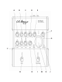
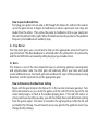
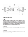
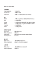
VENUE
Full Isolation D.I.
USER’S GUIDE
www.lrbaggs.com
INTRODUCTION
Thank you for purchasing our Venue D.I. This is the first all-discrete acoustic guitar
preamp to combine a transformer-coupled D.I. output for maximum isolation, an EQ
specifically tuned for acoustic guitars, a variable boost control to compliment your
playing styles and a chromatic digital tuner to help you stay in tune.
We trust that you are going to enjoy and come to understand the full capability of this
new preamp as you use it. We have also included in this manual some tips on how to
get the most out of this product.
TO G E T S TA R T E D
1. Insert a 9-volt battery or plug in a 9-volt DC power supply (not provided).
NOTE: The preamp cannot be phantom powered through the D.I.
2. Plug your guitar into the INPUT of the Venue D.I. (upper right hand side of the box)
and a cable to either the 1/4” OUTPUT (upper left hand side) or the XLR output located
on the back panel of the unit.
3. Adjust the gain knob to the appropriate level using the clip meter.
4. Plug the output cable into your amp or PA and experiment with the features. To learn
more about the specifics of the Venue D.I., continue on with this manual.
A
B
C
D
E
L
G
F
N
H
I
M
K
J
FRONT CONTROLS
A . B a s s Control
The bass control is a 12dB boost/cut centered at a frequency of 90Hz.
B. Low M idrange Controls
This adjustment is split into two knobs: level and frequency. The two knobs are vertically
adjacent to each other; the level knob is the upper one and frequency is directly below
it. Set the frequency knob to a particular frequency (100Hz-500Hz) then either boost or
cut that frequency using the level knob.
C . H i M i d ra n g e Contro l s
The high midrange controls function the same as the low midrange controls except that
they cover the frequency range of 500Hz to 2.8kHz.
D. Presence
The presence control is a 12dB boost/cut centered at 3kHz.
E. Treble
The treble control is a 12dB boost/cut centered at 10kHz.
F. Notch
The Venue D.I. incorporates our proprietary Garrett Null anti-feedback notch filter.
Sonically it is virtually invisible and it can be used to sweep the primary feedback range
of an acoustic guitar (60Hz - 320Hz) to cut out a frequency that is causing feedback or
ringing. This control can also be disabled and taken out of the signal path by turning the
dial all the way to the counter-clockwise position past the “click.”
How to use the Notch Filter
First plug your guitar into an amp or PA through the Venue D.I. and turn the volume
up to the point where it begins to feed back or where a particular note rings out
louder than the others. Then, allow the guitar to feedback a little as you slowly turn
the notch knob from left to right. When the knob reaches the position of the problem
frequency the feedback will suddenly stop.
G. Clip Meter
The Clip meter gives you a visual tool to help set the appropriate amount of gain for
your instrument. The ideal headroom is achieved when the yellow LED is lit consistently
and the red LED blinks occasionally while playing at your loudest level.
H. G ain
This feature is one of the most important keys to achieving optimum sound quality
and signal-to-noise ratio. Too little gain will adversely effect your tone and could
create additional noise. Too much gain will overdrive the input of the preamp causing
distortion. Use the clip meter to set the appropriate gain.
How to Determine the Ideal Gain Setting
Begin with the gain knob on the Venue D.I. in the counter-clockwise position. Turn
the knob clockwise as you strum the guitar until the red LED at the top of the clip
meter barely begins to flash at the loudest playing level. If the red LED comes on
strong continuously while you play, you will most likely hear some distortion coming
from the guitar signal. The meter is located in the signal path just after the EQ and
just before the FX loop. You will need to reset your gain for the optimum level if you
change the EQ settings.
I. Phase
Press this button to invert the polarity of the signal. Usually one phase will sound best
and be least likely to feed back. We recommend trying both phases each time you set
up as it will often change from gig to gig. When the button is in the out position, the
outputs will be in phase with the input signal. The phase relationship of your guitar
top to the monitors or speakers will change approximately every 4 feet that you move
relative to these speakers so you must set this control according to where you will be
standing as you play.
J. Batter y Check
This feature will give you the ability to find out how much battery life is left in the tank
so you’re not caught by surprise in the middle of a gig. To check your battery, push the
button labeled “batt chk” located directly below the clip meter. A full battery will light
up all four LED’s. When only the yellow and red lights are lit you have about 4 hours of
normal playing time remaining before you will run out of power. If only the red light is
illuminated, replace the battery immediately. The battery check will work even when
there is not a cord plugged in.
NOTE: When using a DC Power Supply, the battery check circuit will show the level of the DC
Power Supply. To check the battery level, first remove the DC Power Supply from the DC Input
on the Venue D.I.
K . Tun er
A 1/4” cable must be plugged into the input in order for the tuner to function. To engage
the tuner press the Mute/Tune footswitch. This will simultaneously activate the tuner
and mute all outputs. If the Mute/Tune is engaged but you are not tuning or playing,
the tuner will automatically shut down after 1 minute to save power. However, the mute
will remain engaged. After the tuner has timed out and shut itself off, you will need to
deactivate and then re-activate the tuner by pressing the footswitch twice in order for
the tuner to turn back on.
L. Volume
The master volume, located in the upper right of the control panel, will be used to set the
level of the sound coming out of the 1/4” output ONLY. It will not effect the transformer
coupled D.I. Output, which is pre-set at line level. This will allow you to adjust the level to
your amplifier without changing the level to the PA system. However, both the D.I. and
1/4” output will mute when the mute/tune is engaged.
FOOTSWITCHES
M. Mute/Tune
Use the switch to engage or disengage the mute/tune feature. See the “Tuner” section
above for more details on the tuner.
N. B o ost (0-9dB)
The Boost feature allows you to boost your volume level for a solo or to compensate for
changes in playing style. We’ve provided a boost level-adjustment on the back panel to
give you the ability to pre-set your desired amount of boost.
NOTE: The boost feature on this unit comes after the clip meter in the signal path, so it will
not show up on the clip meter when it is engaged. Therefore, it is VERY IMPORTANT to set the
sound system to allow for the maximum boost that you have chosen.
BOTTOM
B at t e r y D rawe r
Lift the tab on the door to gain access to the battery compartment. Any standard 9V
battery should work. Be sure to maintain the correct polarity by matching the plus (+)
sign on the base of the compartment to the plus (+) sign on the battery, which is the
smaller of the two contact points.
B
C
D
A
G
H
E
F
R E A R A N D S I D E PA N E L S
A. Input
The 1/4” input, located on the upper right side of the unit, is an unbalanced (mono) all
discrete input with a 10 megaohm impedance. It can be used with almost any passive
or active pickup or pickup system. Plugging into the input will turn the system on,
therefore unplugging will turn the system off. Before unplugging from the Venue D.I. be
sure to mute the sound system or amplifier, or a loud pop will occur.
B. EFX S end
Connect a standard 1/4” mono cable from this jack to the input of an effects pedal or
rack device.
C. EFX Return
Connect the return of the output of an effects pedal or rack device to interrupt the signal
and complete the series effect loop.
D. B o ost Level
This allows you to set the level of boost you desire when the boost footswitch is activated.
You have a variable range of 0dB to 9dB of boost available.
E. D.I . O u t p u t ( Transformer Coupled)
The D.I. output is a common way to connect directly into the microphone input on a
mixing desk with a standard microphone cable. This output is transformer-coupled for
maximum isolation from noise and ground loop hum. The signal level is set at 0dBu and
will work into a 600-Ohm or higher input impedance, so you will have plenty of signal
strength to send down long cables.
Note: The XLR output is not effected by the volume control but is effected by all other
controls.
F. G ro u n d L i f t & Tra n s fo r m e r - Cou p l i n g
The transformer-coupled D.I provides full isolation through the D.I. output when the
switch is in the “lift” position to help defeat ground loops that can occur when more
than one connection is made to the D.I.
G. 1/4” O utput
The 1/4” output, located on the upper left side of the unit, is an unbalanced line level
output. You can plug into any amp or device that has a 1/4” input. This output level is
set by the volume control.
H . D. C . I n p u t
The D.C. power input is designed for a standard 2mm plug commonly used with effects
pedals and “floor-box” products. Most “wall-wart” or multi-power devices designed for
musical products may be used. The voltage must be greater than 7.5VDC and less than
14VDC. However, you can use any amperage that is 100mA or greater.
IMPORTANT: Polarity of power supply must match polarity marked on back of Venue: Tip (-),
Ring (+).
S P E C I F I C AT I O N S
1/4” INPUT
Input Impedance
Preamp Gain
Input Level
10 megohms
-12dB to +26dB
-25dBv to +1.8dBv (.053Vrms to 1.23Vrms)
EQ
Notch
Bass
Lo Mid
Hi Mid
Presence
Treble
-21dB, sweepable from 60Hz to 320Hz, 1/8 Octave
+/- 12dB @ 90Hz
+/- 12dB @ 250Hz, sweepable from 100Hz to 500Hz
+/- 12dB @ 1kHz, sweepable from 500Hz to 2.8kHz
+/- 12dB @ 3kHz
+/- 12dB @ 10kHz
EFFECTS LOOPS
Send Level
Output Impedance
Return Level
Input Impedance
0 dBv (0.707Vrms)
600 ohms
0dBv (0.707Vrms) Maximum before clipping
80 Kohms
D.I. OUT
Output level
Output impedance
-1dBv (0.88Vrms) Balanced
600 ohms (Transformer coupled)
LINE OUT
Output level
Output impedance
-1dBv (0.88Vrms) Un-balanced
200 ohms
POWER
DC Power Consumption
DC Current Draw
Voltage Range
Power Supply
Avg. Battery Life
Voltage Range
Signal to Noise
0.65W Max @ 9V
12mA (without tuner), 66mA (with tuner)
7.5VDC Min – 12VDC Max
9VDC with 100mA (or 1Watt) minimum
(Recommended – Not included)
* IMPORTANT: polarity Pos (+) on outside, Gnd (-) on center.
40 hrs. (*depends on tuner usage)
7.5VDC Min – 12VDC Max
90dB, unweighted
PHYSICAL CHARACTERISTICS
2.2 lbs, 7.625” Width x 7.5” Depth x 1.5” Height
· These specifications may change without notice.
www.lrbaggs.com