1
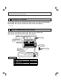
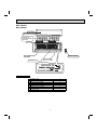
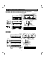
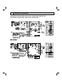
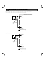
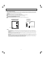
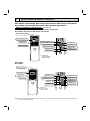
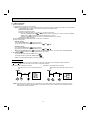
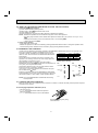
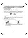
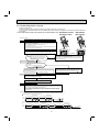
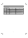
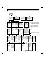
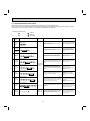
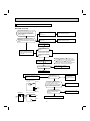
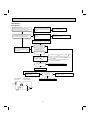
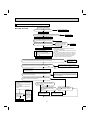
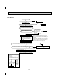
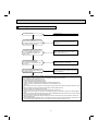
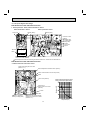
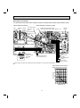
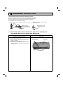
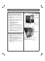
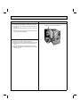
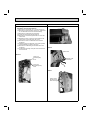
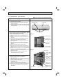
Revision A:
SPLIT-TYPE AIR CONDITIONERS
• MSZ-GE24NA and MSY-GE24NA have been
added.
Please void OBH548.
INDOOR UNIT
No. OBH548
SERVICE MANUAL
REVISED EDITION-A
Models
MSZ-GE06NA
MSZ-GE09NA
MSZ-GE12NA
MSZ-GE15NA
MSZ-GE18NA
MSZ-GE24NA
MSY-GE09NA
MSY-GE12NA
MSY-GE15NA
MSY-GE18NA
MSY-GE24NA
Outdoor unit service manual
MUZ-GE•NA MUY-GE•NA Series (OBH549)
MXZ-B·NA Series (OB444)
CONTENTS
MSZ-GE06/09/12/15/18NA
MSY-GE09/12/15/18NA
1. TECHNICAL CHANGES······································· 2
2. PART NAMES AND FUNCTIONS ····················· 2
3. SPECIFICATION ················································ 4
4. OUTLINES AND DIMENSIONS ························ 6
5. WIRING DIAGRAM············································ 7
6. REFRIGERANT SYSTEM DIAGRAM ··············· 8
7. SERVICE FUNCTIONS ····································· 9
8. MICROPROCESSOR CONTROL ··················· 11
9. TROUBLESHOOTING ····································· 18
10. DISASSEMBLY INSTRUCTIONS ···················· 34
PARTS CATALOG (OBB548)
NOTE:
RoHS compliant products have <G> mark on the spec name plate.
Revision A:
• MSZ-GE24NA and MSY-GE24NA have been added.
1
TECHNICAL CHANGES
MSZ-GE06NA MSZ-GE09NA MSZ-GE12NA MSZ-GE15NA MSZ-GE18NA MSZ-GE24NA
MSY-GE09NA MSY-GE12NA MSY-GE15NA MSY-GE18NA MSY-GE24NA
1. New model
2
PART NAMES AND FUNCTIONS
MSZ-GE06NA MSZ-GE09NA MSZ-GE12NA MSZ-GE15NA MSZ-GE18NA
MSY-GE09NA MSY-GE12NA MSY-GE15NA MSY-GE18NA
Air filter
(Catechin air filter)
Front panel
Air cleaning filter
(Anti-Allergy Enzyme
Filter)
Air inlet
Heat exchanger
Remote controller
Air outlet
Horizontal vane
Display section
Remote control receiving section
Operation indicator lamp
Emergency operation switch (E.O. SW)
ACCESSORIES
Installation plate
Installation plate fixing screw 4 × 25 mm
Remote controller holder
Fixing screw for 3.5 × 1.6 mm (Black)
Battery (AAA) for remote controller
Wireless remote controller
Felt tape (Used for left or left-rear piping)
1
5
1
2
2
1
1
2
MSZ-GE24NA
MSY-GE24NA
Front panel
Air filter
(Nano platinum filter)
Air cleaning filter
(Electrostatic anti-allergy
enzyme filter)
Air inlet
Air outlet
Remote controller
Heat exchanger
Horizontal vane
Display section
ACCESSORIES
Installation plate
Installation plate fixing screw 4 × 25 mm
Remote controller holder
Fixing screw for 3.5 × 1.6 mm (Black)
Battery (AAA) for remote controller
Wireless remote controller
Felt tape (Used for left or left-rear piping)
Air cleaning filter
3
1
7
1
2
2
1
1
2
3
SPECIFICATION
Indoor model
Power supply
V, phase, Hz
Max. fuse size (time delay)/ Disconnect switch A
Min. circuit ampacity
A
Fan motor
F.L.A
COOL Dry CFM
Airflow
(Wet)
Super High - High - Med. Low - Quiet
HEAT Dry CFM
Moisture removal
pt./h
Sound level
Cooling
dB(A)
Super High - High - Med. Heating
dB(A)
Low - Quiet
Cond. drain connection O.D.
in.
W
Dimensions
D
in.
H
Weight
Ib.
External finish
Control voltage (by built-in transformer)
Indoor model
MSZ-GE09NA
MSZ-GE12NA
MSY-GE09NA
MSY-GE12NA
208/230, 1, 60
15
1.0
0.76
399-321-237-170-145
(364-286-201-134-109)
406-321-233-170-145
406-321-237-170-145
–
1.5
2.5
45-37-30-22-19
43-37-30-22-19
43-37-30-22-19
MSZ-GE06NA
5/8
31-7/16
9-1/8
11-5/8
22
Munsell 1.0Y 9.2/0.2
12 - 24 VDC
MSZ-GE15NA
MSY-GE15NA
MSZ-GE18NA
MSY-GE18NA
208/230, 1, 60
Power supply
V, phase, Hz
Max. fuse size (time delay)/ Disconnect switch A
15
Min. circuit ampacity
A
1.0
Fan motor
F.L.A
0.76
COOL Dry CFM
533-420-335-272-205
533-420-339-275-230
Airflow
(Wet)
(498-385-300-237-170) ( 498-385-304-240-194)
Super High - High - Med. Low - Quiet (GE15/18)
Powerful - High - Med - Low HEAT Dry CFM
463-367-304-247-205
512-431-339-275-230
(GE24)
Moisture removal
pt./h
2.7
4.6
Sound level
Cooling
dB(A)
49-44-38-32-26
49-44-38-33-28
Super High - High - Med. Low - Quiet (GE15/18)
dB(A)
46-40-35-30-26
48-43-38-33-28
Powerful - High - Med - Low Heating
(GE24)
Cond. drain connection O.D.
in.
5/8
W
31-7/16
Dimensions
D
in.
9-1/8
H
11-5/8
Weight
Ib.
22
External finish
Munsell 1.0Y 9.2/0.2
Control voltage (by built-in transformer)
12 - 24 VDC
NOTE: Test conditions are based on AHRI 210/240.
4
MSZ-GE24NA
MSY-GE24NA
20
738-628-469-388
(661-562-420-347)
738-628-469-388
2.7
53-49-41-34
52-49-41-32
43-5/16
9-3/8
12-13/16
37
3-1. OPERATING RANGE
(1) POWER SUPPLY
Rated voltage
208/230 V
1 phase
60 Hz
Indoor unit
Guaranteed voltage (V)
Min. 187
208
230
Max. 253
(2) OPERATION
Intake air temperature (°F)
Mode
Condition
Indoor
DB
80
90
67
Standard temperature
Maximum temperature
Cooling
Minimum temperature
Maximum humidity
Standard temperature
Heating Maximum temperature
Minimum temperature
Outdoor
WB
67
73
57
DB
95
115
14
60
67
60
47
75
-4
78%
70
80
70
WB
—
—
—
—
43
65
-5
3-2. OUTLET AIR SPEED AND COVERAGE
Model
MSZ-GE06NA
Mode
Function
HEAT
Dry
Airflow
(CFM)
406
Dry
321
COOL
HEAT
MSZ-GE09NA
MSY-GE09NA
COOL
HEAT
MSZ-GE12NA
MSY-GE12NA
COOL
HEAT
MSZ-GE15NA
MSY-GE15NA
COOL
HEAT
MSZ-GE18NA
MSY-GE18NA
COOL
HEAT
MSZ-GE24NA
MSY-GE24NA
COOL
● The air coverage is the figure up to the
Air speed
Coverage (ft.)
(ft./s.)
position where the air speed is 1 ft./s.,
when air is blown out horizontally from
20.6
29.5
16.3
23.5
Wet
286
14.5
21.0
Dry
406
20.6
29.5
Dry
321
16.3
23.5
Wet
286
14.5
21.0
Dry
406
20.6
29.5
Dry
321
16.3
23.5
Wet
286
14.5
21.0
Dry
463
23.4
33.5
Dry
420
21.3
30.5
Wet
385
19.5
28.0
Dry
512
25.9
36.9
Dry
420
21.3
30.5
Wet
385
19.5
28.0
Dry
738
18.0
36.9
Dry
738
18.0
36.9
Wet
661
16.1
33.2
5
the unit properly at the High speed position.
The coverage should be used only as a
general guideline since it varies according to the size of the room and furniture
arranged inside the room.
4
OUTLINES AND DIMENSIONS
MSZ-GE06NA MSZ-GE09NA MSZ-GE12NA MSZ-GE15NA MSZ-GE18NA
MSY-GE09NA MSY-GE12NA MSY-GE15NA MSY-GE18NA
7/8
6-1/8
13-5/16
1/8
1-5/8
10
8-3/8
1-5/8
6-1/8
2-3/8
13-9/16
Air in
Indoor unit
2-1/8
Wall hole ø2-9/16
Installation plate
24-3/8
1-5/8
5-1/8
4/3/16
1-5/8
Piping
6 - 1/4
Insulation
Liquid line
Gas line
1-15/16
2-3/16
Drain hose
Drain hose
4-3/8
Air out
3/4
1-11/16
2- 5/16
2-3/16
2-11/16
1-15/16
5/16
3-15/16
11-5/8
2-3/16
2-3/4
Piping
1-3/4
ø1 - 3/8 O.D
ø1/4 19 - 11/16 (Flared connection ø1/4)
ø3/8 16 - 15/16
(Flared connection: ø3/8 (GE06/09/12NA), ø1/2 (GE15/18NA))
Insulation ø1-1/8 O.D Connected part ø5/8 O.D
MSZ-GE24NA
MSY-GE24NA
7/16×3/4 Oblong hole
8-7/8
27/32
8-7/8
4-5/16
1-15/16
9-3/8
7-27/32
19-3/4
Air in
1/8
7-27/32
1-3/4
Indoor unit
17-5/16
Installation plate
4-3/8
1-3/4
9-3/8
10-3/16
11
3/16
11-1/16
9-7/16
43-5/16
42-7/8
7/16×1 Oblong hole
5-1/16
Installation plate
Wall hole Ø3
Piping
7-1/8
2-9/16
( 70° )
3/4
Drain hose
2-1/2
2-9/16
1-3/16
2-9/16
6
Piping
2-1/2
Air out
4-7/8
6-5/16
7-1/4
1/8
33-1/8
6-1/4
2-5/16
3
3-15/16
1/2
2-5/8
12-13/16
2-9/16
8-1/4
3/16
2-1/2
Insulation
Liquid line
Gas line
Drain hose
9-15/16
3-1/8
1/4
9-1/8
3/16
8-7/8
9-1/8
31-7/16
30-15/16
8-7/8
3-1/8
8-5/16
7/16×13/16 Oblong hole
7/16×1 Oblong hole
Installation plate
Unit: inch
Ø2 O.D
Ø3/8 19-11/16 (Flared connection Ø3/8)
Ø1/2 16-15/16 (Flared connection Ø5/8)
Insulation Ø1-1/8 Connected part Ø5/8 O.D
5
WIRING DIAGRAM
MSZ-GE06NA MSZ-GE09NA MSZ-GE12NA MSZ-GE15NA MSZ-GE18NA
MSY-GE09NA MSY-GE12NA MSY-GE15NA MSY-GE18NA
MSZ-GE24NA
MSY-GE24NA
7
6
REFRIGERANT SYSTEM DIAGRAM
MSZ-GE06NA MSZ-GE09NA MSZ-GE12NA MSZ-GE15NA MSZ-GE18NA
MSY-GE09NA MSY-GE12NA MSY-GE15NA MSY-GE18NA
Refrigerant pipe ø3/8 (MSZ-GE06/09/12NA, MSY-GE09/12NA)
ø1/2 (MSZ-GE15/18NA, MSY-GE15/18NA)
(with heat insulator)
Indoor
heat
exchanger
Indoor coil
thermistor
RT12 (main)
Flared connection
Indoor coil
thermistor
RT13 (sub)
Room temperature
thermistor
RT11
Flared connection
Refrigerant pipe ø1/4
(with heat insulator)
Refrigerant flow in cooling
Refrigerant flow in heating
MSZ-GE24NA
MSY-GE24NA
Refrigerant pipe ø5/8
(with heat insulator)
Indoor
heat
exchanger
Indoor coil
thermistor
RT12 (main)
Flared connection
Indoor coil
thermistor
RT13 (sub)
Room temperature
thermistor
RT11
Flared connection
Refrigerant pipe ø3/8
(with heat insulator)
Refrigerant flow in cooling
Refrigerant flow in heating
8
Unit: inch
7
SERVICE FUNCTIONS
MSZ-GE06NA MSZ-GE09NA MSZ-GE12NA MSZ-GE15NA MSZ-GE18NA MSZ-GE24NA
MSY-GE09NA MSY-GE12NA MSY-GE15NA MSY-GE18NA MSY-GE24NA
7-1. TIMER SHORT MODE
For service, set time can be shortened by short circuit of JPG and JPS the indoor electronic control P.C. board.
The time will be shortened as follows. (Refer to 9-7.)
Set time: 1-minute → 1-second
Set time: 3-minute → 3-second (It takes 3 minutes for the compressor to start operation. However, the starting time is
shortened by short circuit of JPG and JPS.)
7-2. P.C. BOARD MODIFICATION FOR INDIVIDUAL OPERATION
A maximum of 4 indoor units with wireless remote controllers can be used in a room.
In this case, to operate each indoor unit individually by each remote controller, P.C. boards of remote controller must be
modified according to the number of the indoor unit.
How to modify the remote controller P.C. board
Remove batteries before modification.
The board has a print as shown below:
NOTE: For modification, take out the batteries and
press the OPERATE/STOP (ON/OFF) button
twice or 3 times at first.
After finish modification, put back the batteries
then press the RESET button.
J1
J2
The P.C. board has the print “J1” and “J2”. Solder “J1” and “J2” according to the number of indoor unit as shown in Table 1.
After modification, press the RESET button.
Table 1
1 unit operation
2 units operation
3 units operation
4 units operation
No. 1 unit
No modification
Same as at left
Same as at left
Same as at left
No. 2 unit
—
Solder J1
Same as at left
Same as at left
No. 3 unit
—
—
Solder J2
Same as at left
No. 4 unit
—
—
—
Solder both J1 and J2
How to set the remote controller exclusively for particular indoor unit
After you turn the breaker ON, the first remote controller that sends the signal to the indoor unit will be regarded as the remote
controller for the indoor unit.
The indoor unit will only accept the signal from the remote controller that has been assigned to the indoor unit once they are
set.
The setting will be cancelled if the breaker has turned OFF, or the power supply has shut down.
Please conduct the above setting once again after the power has restored.
9
7-3. AUTO RESTART FUNCTION
When the indoor unit is controlled with the remote controller, the operation mode, the set temperature, and the fan speed
are memorized by the indoor electronic control P.C. board. “AUTO RESTART FUNCTION” automatically starts operation
in the same mode just before the shut-off of the main power.
Operation
If the main power has been cut, the operation settings remain.
After the power is restored, the unit restarts automatically according to the memory.
(However, it takes at least 3 minutes for the compressor to start running.)
How to release “AUTO RESTART FUNCTION”
Turn OFF the main power of the unit.
Solder the Jumper wire JR07 on the indoor electronic control P.C. board. (Refer to 9-7.)
MSZ-GE06/09/12/15/18NA
MSY-GE09/12/15/18NA
CN10A
CN10A
CN151 CN152 CN111
CN112
CN112 CN111
JR07
CN151
Indoor electronic
control P.C. board
MSZ-GE24NA
MSY-GE24NA
Indoor electronic
control P.C. board
JR07
NOTE:
• The operation settings are memorized when 10 seconds have passed after the indoor unit was operated with the
remote controller.
• If main power is turned OFF or a power failure occurs while AUTO START/STOP timer is active, the timer setting is
cancelled.
• If the unit has been OFF with the remote controller before power failure, the auto restart function does not work as
the power button of the remote controller is OFF.
• To prevent breaker OFF due to the rush of starting current, systematize other home appliance not to turn ON at the
same time.
• When some air conditioners are connected to the same supply system, if they are operated before power failure, the
starting current of all the compressors may flow simultaneously at restart.
Therefore, the special counter-measures are required to prevent the main voltage-drop or the rush of the starting
current by adding to the system that allows the units to start one by one.
10
8
MICROPROCESSOR CONTROL
MSZ-GE06NA MSZ-GE09NA MSZ-GE12NA MSZ-GE15NA MSZ-GE18NA MSZ-GE24NA
MSY-GE09NA MSY-GE12NA MSY-GE15NA MSY-GE18NA MSY-GE24NA
WIRELESS REMOTE CONTROLLER
E.g.: MSZ type
MSZ-GE06NA MSZ-GE09NA MSZ-GE12NA MSZ-GE15NA MSZ-GE18NA
MSY-GE09NA MSY-GE12NA MSY-GE15NA MSY-GE18NA
Signal transmitting section
Operation display section
OPERATE/STOP
(ON/OFF) button
Temperature buttons
FAN SPEED CONTROL button
OPERATION SELECT button
OFF TIMER button
ECONO COOL button
ON TIMER button
VANE CONTROL button
TIME SET buttons
FORWARD button
BACKWARD button
SMART SET button
RESET button
CLOCK SET button
Indication of
remote controller
model is on back
MSZ-GE24NA
MSY-GE24NA
Signal transmitting section
Operation display section
OPERATE/STOP
(ON/OFF) button
VANE CONTROL button
(Horizontal vane button)
OPERATION SELECT button
Temperature buttons
ECONO COOL button
WIDE VANE button
(Vertical vane button)
POWERFUL button
RESET button
FAN SPEED CONTROL button
OFF TIMER button
ON TIMER button
TIME SET buttons
FORWARD button
BACKWARD button
CLOCK SET button
Indication of
remote controller
model is on back
NOTE: Last setting will be stored after the unit is turned OFF with the remote controller. Indoor unit receives the signal of the
remote controller with beeps.
11
INDOOR UNIT DISPLAY SECTION
Operation Indicator lamp
The operation indicator at the right side of the indoor unit indicates the operation state.
• The following indication applies regardless of shape of the indication.
Indication
Operation state
Room temperature
Lighted
Blinking
Not lighted
The unit is operating to
reach the set temperature
About 4°F(2°C) or more
away from set temperature
The room temperature is
approaching the set temperature
About 2 to 4°F(1 to 2°C)
from set temperature
Standby mode
(Only during multi system
operation)
8-1. COOL (
-
) OPERATION
(1) Press OPERATE/STOP (ON/OFF) button.
OPERATION INDICATOR lamp of the indoor unit turns ON with a beep tone.
(2) Select COOL mode with OPERATION SELECT button.
(3) Press TEMPERATURE buttons (TOO WARM or TOO COOL button) to select the desired temperature.
The setting range is 61 ~ 88°F (16 ~ 31°C).
1. Coil frost prevention
The compressor operational frequency is controlled by the temperature of the indoor heat exchanger to prevent the coil from
frosting.
When the temperature of indoor heat exchanger becomes too low, the coil frost prevention mode works.
The indoor fan operates at the set speed and the compressor stops. This mode continues until the temperature of indoor
heat exchanger rises.
2. Low outside temperature operation
When the outside temperature is lower, low outside temperature operation starts, and the outdoor fan slows or stops.
8-2. DRY (
) OPERATION
(1) Press OPERATE/STOP (ON/OFF) button.
OPERATION INDICATOR lamp of the indoor unit turns ON with a beep tone.
(2) Select DRY mode with OPERATION SELECT button.
(3) The set temperature is determined from the initial room temperature.
1. Coil frost prevention
Coil frost prevention is as same as COOL mode. (8-1.1.)
2. Low outside temperature operation
Low outside temperature operation is as same as COOL mode. (8-1.2.)
12
8-3. HEAT (
) OPERATION (MSZ)
(1) Press OPERATE/STOP (ON/OFF) button.
OPERATION INDICATOR lamp of the indoor unit turns ON with a beep tone.
(2) Select HEAT mode with OPERATION SELECT button.
(3) Press TEMPERATURE buttons (TOO WARM or TOO COOL button) to select the desired temperature.
The setting range is 61 ~ 88°F (16 ~ 31°C).
1. Cold air prevention control
When the compressor is not operating or is starting, and the temperature of indoor heat exchanger and/or the room temperature is low or when defrosting is being done, the indoor fan will stop or rotate in Very Low speed.
2. High pressure protection
The compressor operational frequency is controlled by the temperature of the indoor heat exchanger to prevent the condensing pressure from increasing excessively.
When the temperature of indoor heat exchanger becomes too high, the high pressure protection works.
The indoor fan operates following the cold air prevention control. This mode continues until the temperature of indoor heat
exchanger falls.
3. Defrosting
Defrosting starts when the temperature of outdoor heat exchanger becomes too low.
The compressor stops once, the indoor/outdoor fans stop, the 4-way valve reverses and the compressor re-starts.
This mode continues until the temperature of outdoor heat exchanger rises or the fixed time passes.
8-4. FAN(
)OPERATION (MSY)
(1) Press OPERATE/STOP (ON/OFF) button.
OPERATION INDICATOR lamp of the indoor unit turns ON with a beep tone.
(2) Select FAN mode with OPERATION SELECT button.
(3) Select the desired fan speed. When AUTO, it becomes Low.
Only indoor fan operates. Outdoor unit does not operate.
8-5. “I FEEL CONTROL” (
) OPERATION (MSY)
(1) Press OPERATE/STOP (ON/OFF) button on the remote controller. OPERATION INDICATOR lamp of the indoor unit
turns ON with a beep tone.
(2) Select “I FEEL CONTROL” mode with OPERATION SELECT button.
(3) The operation mode is determined by the room temperature at start-up of the operation.
• Once the mode is fixed, the mode does not change by room temperature afterwards.
• Under the ON TIMER (
) operation, mode is determined according to the room temperature at the start-up of
operation.
(4) The initial set temperature is decided by the initial room temperature.
Initial room temperature
Model
Initial set temperature
79°F (26°C) or more
75°F (24°C)
COOL mode of
"I FEEL CONTROL"
77 to 79°F (25 to 26°C)
Less than 79°F (25°C)
Initial room temperature minus 4°F (2°C)
DRY mode of
"I FEEL CONTROL"
Initial room temperature minus 4°F (2°C)
(5) TEMPERATURE buttons
In “I FEEL CONTROL” (
) mode, set temperature is decided by the microprocessor based on the room temperature.
In addition, set temperature can be controlled by TOO WARM or TOO COOL buttons when you feel too cool or too
warm.
Each time the TOO WARM or TOO COOL button is pressed, the indoor unit receives the signal and emits a beep tone.
• Fuzzy control
When the TOO COOL or TOO WARM button is pressed, the microprocessor changes the set temperature, considering the room temperature, the frequency of pressing TOO COOL or TOO WARM button and the user's preference to
heat or cool. So this is called “Fuzzy control”, and works only in “I FEEL CONTROL” mode.
In DRY mode of “I FEEL CONTROL”, the set temperature does not change.
TOO
COOL
TOO
WARM
…To raise the set temperature 2~4°F (1~2°C)
13
…To lower the set temperature 2~4°F (1~2°C)
8-6. AUTO CHANGE OVER ··· AUTO MODE OPERATION (MSZ)
Once desired temperature is set, unit operation is switched automatically between COOL and HEAT operation.
Mode selection
(1) Initial mode
When unit starts the operation with AUTO operation from OFF:
• If the room temperature is higher than the set temperature, operation starts in COOL mode.
• If the room temperature is equal to or lower than the set temperature, operation starts in HEAT mode.
(2) Mode change
COOL mode changes to HEAT mode when about 15 minutes have passed with the room temperature 2°F (1°C) below
the set temperature.
HEAT mode changes to COOL mode when about 15 minutes have passed with the room temperature 2°F (1°C) above
the set temperature.
NOTE1
If two or more indoor units are operating in multi system, there might be a case that the indoor unit, which is operating in
(AUTO), cannot change over to the other operating mode (COOL ↔ HEAT(MSZ)) and becomes a state of standby.
Refer to NOTE2 "FOR MULTI SYSTEM AIR CONDITIONER".
NOTE2
FOR MULTI SYSTEM AIR CONDITIONER
OUTDOOR UNIT: MXZ series
Multi system air conditioner can connect two or more indoor units with one outdoor unit.
• When you try to operate two or more indoor units with one outdoor unit simultaneously, one for the cooling and
the others for heating, the operation mode of the indoor unit that operates first is selected. Other indoor units
cannot operate, and operation indicator lamp flashes as shown in the figure below. In this case, please set all the
indoor units to the same operation mode.
<Operation indicator lamp>
Lighted
Blinking
Not lighted
• When indoor unit starts the operation while the defrosting of outdoor unit is being done, it takes a few minutes (max.
10 minutes) to blow out the warm air.
• In the heating operation, though indoor unit that does not operate may get warm or the sound of refrigerant flowing may be heard, they are not malfunction. The reason is that the refrigerant continuously flows into it.
8-7. AUTO VANE OPERATION
1. Horizontal vane
(1) Vane motor drive
These models are equipped with a stepping motor for the horizontal vane. The rotating direction, speed, and angle of
the motor are controlled by pulse signals (approx. 12 V) transmitted from indoor microprocessor.
(2) The horizontal vane angle and mode change as follows by pressing VANE CONTROL button.
(3) Positioning
To confirm the standard position, the vane moves until it touches the vane stopper. Then the vane is set to the selected
angle.
Confirming of standard position is performed in the following cases:
(a) When the operation starts or finishes (including timer operation).
(b) When the test run operation starts.
(c) When standby mode (only during multi system operation) starts or finishes.
14
(4) VANE AUTO (
) mode
The microprocessor automatically determines the vane angle to make the optimum room temperature distribution.
In COOL and DRY operation
Vane angle is fixed to Horizontal position.
In HEAT operation
Vane angle is fixed to Angle 5.
Horizontal
position
5
(5) STOP (operation OFF) and ON TIMER standby
In the following cases, the horizontal vane returns to the closed position.
(a) When OPERATE/STOP (ON/OFF) button is pressed (POWER OFF).
(b) When the operation is stopped by the emergency operation.
(c) When ON TIMER is ON standby.
(6) Dew prevention
During COOL or DRY operation with the vane angle at Angle 4 or 5 when the compressor cumulative operation time
exceeds 1 hour, the vane angle automatically changes to Angle 1 for dew prevention.
(7) SWING (
) mode
By selecting SWING mode with VANE CONTROL button, the horizontal vane swings vertically.
(8) Cold air prevention in HEAT operation (MSZ)
The horizontal vane position is set to Upward.
NOTE: When 2 or more indoor units are operated with multi outdoor unit, even if any indoor unit turns thermostat OFF,
this control does not work in the indoor unit.
(9) ECONO COOL ( ) operation (ECONOmical operation)
When ECONO COOL button is pressed in COOL mode, set temperature is automatically set 4°F(2°C) higher.
Also the horizontal vane swings in various cycle.
SWING operation makes you feel cooler than set temperature. So, even though the set temperature is higher, the air
conditioner can keep comfort. As a result, energy can be saved.
To cancel this operation, select a different mode or press one of the following buttons in ECONO COOL operation:
ECONO COOL, VANE CONTROL, or POWERFUL(MSZ/MSY-GE24NA) button.
(10) POWERFUL (
) operation. (MSZ-GE24NA MSY-GE24NA)
The air conditioner automatically adjusts the fan speed and the set temperature, and operates the POWERFUL mode.
The POWERFUL mode is automatically released 15 minutes after operation starts, and the operation mode returns
to the mode prior to POWERFUL operation. To manually cancel this operation, select a different mode or press
POWERFUL or ECONO COOL button.
2. Vertical vane (MSZ-GE24NA MSY-GE24NA)
(1) Vane motor drive
These models are equipped with a stepping motor for the vertical vane. The rotating direction, speed, and angle of the
motor are controlled by pulse signals (approx. 12 V) transmitted from microprocessor.
(2) The vertical vane angle and mode change as follows by pressing WIDE VANE button.
1
2
3
4
SWING
5
6
(3) Positioning
(a) When OPERATE/STOP (ON/OFF) button is pressed (POWER ON).
(b) When SWING is started.
(c) When the power supply turns ON.
(4) SWING MODE (
)
By selecting SWING mode with WIDE VANE button, the vertical vane swings horizontally.
The remote controller displays “ ”. Swing mode is cancelled when WIDE MODE button is pressed once again.
(5) WIDE MODE (
)
By selecting WIDE mode with WIDE VANE button, indoor fan speed becomes faster than setting fan speed on the
remote controller ( ). The remote controller displays “
”.
NOTE: Indoor fan speed becomes faster than setting fan speed on the remote controller even when
or
selected.
15
is
8-8. TIMER OPERATION
1. How to set the time
(1) Check that the current time is set correctly.
NOTE: Timer operation will not work without setting the current time. Initially “0:00 AM” blinks at the current time display
of TIME MONITOR, so set the current time correctly with CLOCK SET button.
How to set the current time
(a) Press the CLOCK set button.
) to set the current time.
(b) Press the TIME SET buttons (
and
• Each time FORWARD button (
) is pressed, the set time increases by 1 minute, and each time BACKWARD button (
) is pressed, the set time decreases by 1 minute.
• Pressing those buttons longer, the set time increases/decreases by 10 minutes.
(c) Press the CLOCK set button.
(2) Press OPERATE/STOP (ON/OFF) button to start the air conditioner.
(3) Set the time of timer.
ON timer setting
(a) Press ON TIMER button (
) during operation.
).
(b) Set the time of the timer using TIME SET buttons (
and
OFF timer setting
(a) Press OFF TIMER button (
) during operation.
).
(b) Set the time of the timer using TIME SET buttons (
and
Each time FORWARD button (
) is pressed, the set time increases by 10 minutes: each time BACKWARD
button (
) is pressed, the set time decreases by 10 minutes.
2. To release the timer
To release ON timer, press ON TIMER button (
).
To release OFF timer, press OFF TIMER button (
).
TIMER is cancelled and the display of set time disappears.
PROGRAM TIMER
• OFF timer and ON timer can be used in combination. The timer of the set time that is reached first will operate first.
• “ ” and “ ” display shows the order of OFF timer and ON timer operation.
(Example 1) The current time is 8:00 PM.
The unit turns OFF at 11:00 PM, and ON at 6:00
AM.
(Example 2) The current time is 11:00 AM.
The unit turns ON at 5:00 PM, and OFF at 9:00
PM.
PM
PM
AM
PM
NOTE: If the main power is turned OFF or a power failure occurs while ON/OFF timer is active, the timer setting is cancelled. As these models are equipped with an auto restart function, the air conditioner starts operating with timer
cancelled when power is restored.
16
8-9. SMART SET ( ) OPERATION (MSZ-GE06/09/12/15/18NA MSY-09/12/15/18NA)
1. How to SET SMART SET operation
(1) Press OPERATE/STOP (ON/OFF) button.
(2) Select COOL, HEAT (MSZ) or ECONO COOL mode.
(3) Press SMART SET button.
(4) Set the temperature, fan speed, and airflow direction for SMART SET operation.
NOTE: • SMART SET operation cannot be selected during DRY or AUTO mode operation.
• The setting range of HEAT mode in SMART SET operation is between 50°F (10°C) and 61 - 87°F (16 - 31°C)
(MSZ).
• 2 settings can be saved. (One for COOL/ECONO COOL, one for HEAT) (MSZ).
• 1 setting can be saved. (MSY).
2. How to cancel operation
• Press SMART SET button again.
• SMART SET operation can also be cancelled by pressing OPERATION SELECT button to change the operation mode.
The same setting will be selected from the next time by simply pressing SMART SET button.
8-10. EMERGENCY/TEST OPERATION
In case of test run operation or emergency operation, use EMERGENCY OPERATION switch on the right side of the
indoor unit. Emergency operation is available when the remote
controller is missing, has failed or the batteries of the remote conOperation mode
COOL
HEAT (MSZ)
troller run down. The unit will start and OPERATION INDICATOR
Set temperature
75°F(24°C)
75°F(24°C)
lamp will light.
Fan speed
Med.
Med.
The first 30 minutes of operation is the test run operation. This
Horizontal vane
Auto
Auto
operation is for servicing. The indoor fan runs at High speed and
The operation mode is indicated by the Operation
the temperature control does not work.
Indicator lamp as following
After 30 minutes of test run operation, the system shifts to
MSY
EMERGENCY COOL/HEAT(MSZ) MODE with a set temperature of MSZ
75°F (24°C). The fan speed shifts to Med.
EMERGENCY
EMERGENCY
COOL
COOL
All protective operations such as the coil frost prevention works
even in the test run or emergency operation.
↓
↓
In the test run or emergency operation, the horizontal vane operEMERGENCY
ates in VANE AUTO ( ) mode.
STOP
HEAT
Emergency operation continues until EMERGENCY OPERATION
switch is pressed once or twice or the unit receives any signal from
↓
Lighted
the remote controller. In case of latter, normal operation will start.
Not lighted
STOP
NOTE: Do not press EMERGENCY OPERATION switch during
normal operation.
8-11. 3-MINUTE TIME DELAY OPERATION
When the system turns OFF, compressor will not restart for 3 minutes as 3-minute time delay function operates to protect
compressor from overload.
8-12. Changing temperature indication (°F/°C)
• The preset unit is °F.
• °F → °C: Press RESET button while the temperature
buttons are pressed.
• °C → °F: Press RESET button or remove the batteries .
Press RESET button gently using
a thin instrument.
17
9
TROUBLESHOOTING
MSZ-GE06NA MSZ-GE09NA MSZ-GE12NA MSZ-GE15NA MSZ-GE18NA MSZ-GE24NA
MSY-GE09NA MSY-GE12NA MSY-GE15NA MSY-GE18NA MSY-GE24NA
9-1. CAUTIONS ON TROUBLESHOOTING
1. Before troubleshooting, check the following
1) Check the power supply voltage.
2) Check the indoor/outdoor connecting wire for miswiring.
2. Take care of the following during servicing
1) Before servicing the air conditioner, be sure to turn OFF the unit first with the remote controller, and then after confirming the horizontal vane is closed, turn OFF the breaker and/or disconnect the power plug.
2) Be sure to turn OFF the power supply before removing the front panel, the cabinet, the top panel, and the P.C. board.
3) When removing the P.C. board, hold the edge of the board with care NOT to apply stress on the components.
4) When connecting or disconnecting the connectors, hold the housing of the connector. DO NOT pull the lead wires.
<Incorrect>
<Correct>
Lead wiring
Housing point
3. Troubleshooting procedure
1) First, check if the OPERATION INDICATOR lamp on the indoor unit is flashing ON and OFF to indicate an abnormality.
To make sure, check how many times the OPERATION INDICATOR lamp is flashing ON and OFF before starting service work.
2) Before servicing check that the connector and terminal are connected properly.
3) When the P.C. board seems to be defective, check the copper foil pattern for disconnection and the components for
bursting and discoloration.
4) When troubleshooting, refer to 9-2, 9-3 and 9-4.
4. How to replace batteries
Weak batteries may cause the remote controller malfunction.
In this case, replace the batteries to operate the remote controller normally.
Press RESET button with a thin instrument, and
then use the remote controller.
Remove the front lid and insert batteries.
Then reattach the front lid.
Insert the negative pole of the
batteries first. Check if the polarity
of the batteries is correct.
RESET button
NOTE: 1. If RESET button is not pressed, the remote controller may not operate correctly.
2. This remote controller has a circuit to automatically reset the microcomputer when batteries are replaced.
This function is equipped to prevent the microcomputer from malfunctioning due to the voltage drop caused by
the battery replacement.
3. Do not use the leaking batteries.
18
9-2. FAILURE MODE RECALL FUNCTION
Outline of the function
This air conditioner can memorize the abnormal condition which has occurred once.
Even though LED indication listed on the troubleshooting check table (9-4.) disappears, the memorized failure details can
be recalled.
1. Flow chart of failure mode recall function for the indoor/outdoor unit MSZ-GE06/09/12/15/18NA
MSZ-GE24NA
MSY-GE24NA
MSY-GE09/12/15/18NA
Operational procedure
The cause of abnormality cannot be found because the abnormality does not recur.
Setting up the failure mode recall function
Turn ON the power supply.
<Preparation of the remote controller>
While pressing both OPERATION SELECT button and TOO COOL button on the
remote controller at the same time, press RESET button.
First, release RESET button.
And release the other two buttons after all LCD in operation display section of the
remote controller is displayed after 3 seconds.
Press OPERATE/STOP (ON/OFF) button of the remote controller (the set temperature is
displayed) with the remote controller headed towards the indoor unit. 1
E.g.: MSZ type
Does upper lamp of OPERATION INDICATOR
lamp on the indoor unit blink at the interval of 0.5
seconds?
Blinks: Either indoor or outdoor unit is abnormal.
Beep is emitted at the same timing as the
blinking of upper lamp of OPERATION
INDICATOR lamp. 2
Yes
(Blinks)
Judgment of indoor/outdoor abnormality
Before blinking, does upper lamp of
OPERATION INDICATOR lamp stay ON for 3
seconds?
Yes
Stays ON for 3 seconds (without beep):
The outdoor unit is abnormal.
No
Indoor unit is normal.
But the outdoor unit might be abnormal because there are some abnormalities that can not be recalled with this way.
Confirm if outdoor unit is abnormal according to the detailed outdoor unit
failure mode recall function.
No
(OFF)
1 Regardless of normal or abnormal condition,
a short beep is emitted once the signal is received.
The indoor unit is abnormal.
Check the blinking pattern, and confirm the abnormal point with the indoor unit
failure mode table. (Refer to 9-2.2)
Make sure to check at least two consecutive blinking cycles. 2
The outdoor unit is abnormal.
Check the blinking pattern, and confirm the abnormal point with the
outdoor unit failure mode table. (Refer to outdoor unit service manual.)
Make sure to check at least two consecutive blinking cycles. 3
Releasing the failure mode recall function
Release the failure mode recall function by the following procedures.
Turn OFF the power supply and turn it ON again.
Press RESET button of the remote controller.
Repair the defective parts.
Deleting the memorized abnormal condition
After repairing the unit, recall the failure mode again according to "Setting up the failure mode recall
function" mentioned above.
Press OPERATE/STOP (ON/OFF) button of the remote controller (the set temperature is displayed)
with the remote controller headed towards the indoor unit.
Press EMERGENCY OPERATION switch so that the memorized abnormal condition is deleted.
Release the failure mode recall function according to "Releasing the failure mode recall function"
mentioned above.
NOTE: 1. Make sure to release the failure mode recall function once it is set up, otherwise the unit cannot operate properly.
2. If the abnormal condition is not deleted from the memory, the last abnormal condition is kept memorized.
2. Blinking pattern when the indoor unit is abnormal:
Blinking at 0.52.5-second OFF second interval
Blinking at 0.52.5-second OFF second interval
ON
OFF
Beeps
Repeated cycle
Beeps
Repeated cycle
3.Blinking pattern when the outdoor unit is abnormal:
Blinking at 0.52.5-second OFF
3-second ON
second interval
Beeps
Repeated cycle
2.5-second OFF
3-second ON
Blinking at 0.5second interval
ON
OFF
No beep
Repeated cycle
Beeps
No beep
Repeated cycle
19
Beeps
Repeated cycle
2. Indoor unit failure mode table
Upper lamp of OPAbnormal point
ERATION INDICA(Failure mode)
TOR lamp
Not lighted
Normal
Condition
Remedy
—
The room temperature thermistor short or
1-time flash every Room temperature
open circuit is detected every 8 seconds dur0.5-second
thermistor
ing operation.
Indoor coil
2-time flash
The indoor coil thermistor short or open circuit
2.5-second OFF
is detected every 8 seconds during operation.
thermistor
3-time flash
The serial signal from outdoor unit is not reSerial signal
2.5-second OFF
ceived for a maximum of 6 minutes.
The rotational frequency feedback signal is
11-time flash
Indoor fan motor
not emitted for 12 seconds after the indoor fan
2.5-second OFF
motor is operated.
It cannot properly read data in the nonvolatile
12-time flash
Indoor control
memory of the indoor electronic control P.C.
2.5-second OFF
system
board.
—
Refer to the characteristics of the room temperature
thermistor (9-7.2.).
Refer to the characteristics of the main indoor coil thermistor, the sub indoor coil thermistor (9-7.2.).
Refer to 9-6. "How to check miswiring and serial
signal error".
Refer to 9-6.
"Check of indoor fan motor".
Replace the indoor electronic control P.C. board.
NOTE: Blinking patterns of this mode differ from the ones of TROUBLESHOOTING CHECK TABLE (9-4.).
20
9-3. INSTRUCTION OF TROUBLESHOOTING
Start
Indoor unit operates.
Outdoor unit
does not operate.
Outdoor unit
operates only
in Test Run
operation.
Outdoor unit
does not
operate even
in Test Run
operation.
Indoor unit operates.
Outdoor unit does
not operate normally.
Unit does not
operate normal operation
in COOL or
HEAT mode.
Indoor unit does
not receive the
signal from remote controller.
Indoor unit
operates, when
EMERGENCY
OPERATION
switch is pressed.
OPERATION INDICATOR
lamp on the indoor unit is
flashing ON and OFF.
"Test Run operation" means the
operation within 30 minutes after EMERGENCY OPERATION
switch is pressed.
Indoor unit does
not operate, when
EMERGENCY
OPERATION
switch is pressed.
If blinking of OPERATION INDICATOR lamp cannot be checked,
it can be checked with failure
mode recall function.
Check room
temperature
thermistor.
Refer to 9-7.
"Test point
diagram and
voltage".
Refer to "How
to check
inverter/compressor".
Refer to
"Check of R.V.
coil".
Refer to 9-6.
"Check of remote
controller and
indoor electronic control P.C.
board".
1. Check indoor/outdoor connecting wire.
(Check if the power is
supplied to the indoor
unit.)
2. Refer to 9-6. "Check
of indoor P.C. board
and indoor fan motor".
Refer to outdoor unit service manual.
Upper lamp
Flash ON
and OFF at
0.5-second
intervals
Cause:
Indoor/Outdoor
unit
• Miswiring or
trouble of
serial signal.
Upper lamp
2-time flash
Cause:
Indoor unit
• Trouble
of room
temperature
/ indoor coil
thermistor.
Upper lamp
3-time flash
Cause:
Indoor unit
• Trouble of
indoor fan
motor.
Upper lamp
4-time flash
Cause:
Indoor unit
• Trouble
of indoor
unit control
system.
Upper lamp
5-time flash
Cause:
Outdoor unit
• Outdoor
power system abnormality.
Upper lamp
6-time flash
Cause:
Outdoor unit
• Trouble of
thermistor in
outdoor unit.
Upper lamp
7-time flash
Cause:
Outdoor unit
• Trouble of
outdoor control system.
Upper lamp
14-time flash
Cause:
Outdoor unit
• Other abnormality
Refer to 9-6.
"How to
check miswiring and
serial signal
error".
Check room Refer to 9-6.
temperature
"Check of
thermistor
indoor fan
and indoor
motor".
coil thermistor. Refer
to 9-7."Test
point diagram
and voltage".
Replace the
indoor electronic control
P.C. board.
Refer to
"How to
check
inverter/compressor".
Refer to
"Check of
outdoor thermistors".
Replace the
inverter P.C.
board or
the outdoor
electronic
control P.C.
board.
Check "Flow
chart of the
detailed
outdoor unit
failure mode
recall function."
21
9-4. TROUBLESHOOTING CHECK TABLE
Before taking measures, make sure that the symptom reappears for accurate troubleshooting.
When the indoor unit has started operation and detected an abnormality of the following condition (the first detection after the
power ON), the indoor fan motor turns OFF and OPERATION INDICATOR lamp flashes.
OPERATION INDICATOR
Lighted
Blinking
Not lighted
No.
1
Abnormal
point
Miswiring
or serial
signal
Indoor coil
thermistor
2
Room temperature
thermistor
Operation indicator lamp
Symptom
Condition
Upper lamp flashes.
0.5-second ON
Remedy
The serial signal from the outdoor unit is not
received for 6 minutes.
• Refer to 9-6. "How to check
miswiring and serial signal error".
The indoor coil or the room temperature thermistor is short or open circuit.
• Refer to the characteristics of
indoor coil thermistor, and the
room temperature thermistor
(9-7.2).
The rotational frequency feedback signal is
not emitted during the indoor fan operation.
• Refer to 9-6. "Check of indoor fan motor".
It cannot properly read data in the nonvolatile
memory of the indoor electronic control P.C.
board.
• Replace the indoor electronic
control P.C. board.
0.5-second OFF
Upper lamp flashes.
2-time flash
2.5-second OFF
Upper lamp flashes.
3-time flash
3
Indoor fan
motor
2.5-second OFF
Upper lamp flashes.
4-time flash
4
Indoor control system
2.5-second OFF
5
Outdoor
power system
Upper lamp flashes.
5-time flash
Indoor unit and
outdoor unit do
not operate.
2.5-second OFF
to "How to check of inIt consecutively occurs 3 times that the com- • Refer
verter/compressor".
pressor stops for overcurrent protection or
Refer
to outdoor unit service
start-up failure protection within 1 minute after manual
start-up.
• Check the stop valve.
Upper lamp flashes.
6-time flash
6
Outdoor
thermistors
The outdoor thermistors short or open circuit
during the compressor operation.
• Refer to "Check of outdoor
thermistor".
Refer to outdoor unit service
manual.
It cannot properly read data in the nonvolatile
memory of the inverter P.C. board or the outdoor electronic control P.C. board.
• Replace the inverter P.C. board
or the outdoor electronic control
P.C. board.
Refer to outdoor unit service
manual.
An abnormality other than above mentioned
is detected.
• Check the stop valve.
• Confirm the abnormality in detail using the failure mode recall
function for outdoor unit.
It cannot properly read data in the nonvolatile
memory of the inverter P.C. board or the outdoor electronic control P.C. board.
• Check the blinking pattern of
the LED on the inverter P.C.
board or the outdoor electronic
control P.C. board.
2.5-second OFF
7
Outdoor
control system
Upper lamp flashes.
7-time flash
2.5-second OFF
Upper lamp flashes.
14-time flash
8
Other abnormality
2.5-second OFF
9
Outdoor
control sys- Upper lamp lights up
tem
Outdoor unit
does not operate
22
OPERATION INDICATOR
No.
Abnormal
point
Operation indicator lamp
Symptom
Remedy
Condition
Upper lamp lights and lower lamp flashes.
1
MXZ type
Operation
mode
setting
The operation mode of the each indoor unit
Outdoor unit
is differently set to COOL (includes DRY) and • Unify the operation mode.
operates but
HEAT at the same time, the operation mode
Refer to outdoor unit service
indoor unit does
of the indoor unit that has operated at first has manual.
not operate.
the priority.
2.5-second OFF
9-5. TROUBLE CRITERION OF MAIN PARTS
MSZ-GE06NA MSZ-GE09NA MSZ-GE12NA MSZ-GE15NA MSZ-GE18NA MSZ-GE24NA
MSY-GE09NA MSY-GE12NA MSY-GE15NA MSY-GE18NA MSY-GE24NA
Part name
Room temperature
thermistor (RT11)
Indoor coil thermistor
(RT12, RT13)
Indoor fan motor (MF)
Check method and criterion
Measure the resistance with a tester.
Figure
Refer to 9-7. "Test point diagram and voltage", "2. Indoor electronic control
P.C. board", for the chart of thermistor.
Check 9-6.
Measure the resistance between the terminals with a tester.
MSZ-GE06/09/12/15/18NA (Temperature: 50 - 86°F (10 - 30°C))
MSY-GE09/12/15/18NA
Color of the lead wire
Normal
Vane motor (MV)
RED - BLK
223 - 268 Ω
MSZ-GE24NA
MSY-GE24NA
Horizontal vane motor
(MV1)
Vertical vane motor
(MV2)
Measure the resistance between the terminals with a tester.
(Part temperature 50 ~ 86°F (10 ~ 30°C))
Color of the lead wire
Horizontal vane motor (MV1)
Vertical vane motor (MV2)
RED-BLK
23
Normal
313 ~ 375 Ω
268 ~ 322 Ω
BLK
ROTOR
BLK
RED
BLK
BLK
BLK
ROTOR
BLK
RED
BLK
BLK
9-6. TROUBLESHOOTING FLOW
A Check of indoor fan motor
MSZ-GE06/09/12/15/18NA
MSY-GE09/12/15/18NA
The indoor fan motor error has occurred, and the indoor fan does not operate.
Turn OFF the power supply.
Pay enough attention to the high voltage on the fan motor connector.
Is there any foreign matter that interferes
the rotation of the line flow fan?
No
Yes
Remove the foreign matter and
adjust the line flow fan.
Is there 294/325 VDC
between CN211 (+)
and (–) ?
Turn ON the power supply, wait 5 seconds or more, and then press
EMERGENCY OPERATION switch.
Measure the supply voltage as follows within 12 seconds after EMERGENCY OPERATION switch is pressed.
If more than 12 seconds passes, turn OFF the power supply and turn it
ON again, then measure the voltage.
<Indoor power P.C. board>
1. Measure the voltage between CN211 (+) and (–).
2. Measure the voltage between CN211 (+) and (–).
<Indoor electronic control P.C. board>
3. Measure the voltage between CN10A (+) and JPG(GND)(–).
If more than 12 seconds passes after EMERGENCY OPERATION switch
is pressed, the voltage measured at 2. above goes 0 VDC although the
indoor P.C. board is normal.
Does the voltage between CN211
(+) and (–) on the power P.C. board
rise to the range of 2 to 6 VDC within
12 seconds after EMERGENCY
OPERATION switch is pressed?
Yes
Yes
Replace the indoor fan motor.
No
No
Replace the indoor power
P.C. board and the indoor
terminal P.C. board.
Yes
Does the voltage between CN10A
(+) and JPG (GND)(–) on the indoor
electronic control P.C. board fall to
2 V or less within 12 seconds after
EMERGENCY OPERATION switch is
pressed?
No
Replace the indoor electronic
control P.C. board.
The indoor fan motor error has occurred, and the indoor fan repeats "12-second ON and 30-second OFF" 3 times, and then stops.
Measure the voltage between CN211
(+) and (–) while the fan motor is
rotating.
Is it unchanged holding
0 or 15 VDC?
Yes
(Unchanged)
Measure the voltage CN10A (+)
and JPG (GND)(–) on the indoor
No
electronic control P.C board when
(Changed) the fan motor is rotaring.
Replace the indoor fan motor.
Replace the indoor power P.C.
board and the indoor terminal P.C.
board.
Is it unchanged holding
0 or 15 VDC?
Yes
(Unchanged)
24
No
(Changed)
Replace the indoor
electronic control P.C.
board.
MSZ-GE24NA
MSY-GE24NA
The indoor fan motor error has occurred, and the indoor fan does not operate.
Turn OFF the power supply.
Pay enough attention to the high voltage on the fan motor connector.
Is there any foreign matter that interferes
the rotation of the line flow fan?
Yes
Remove the foreign matter and
adjust the line flow fan.
Is there 294/325 VDC
between CN211 (+)
and (–) ?
No
Turn ON the power supply, wait 5 seconds or more, and then press
EMERGENCY OPERATION switch.
Measure the supply voltage as follows within 12 seconds after EMERGENCY OPERATION switch is pressed.
If more than 12 seconds passes, turn OFF the power supply and turn it
ON again, then measure the voltage.
<Indoor electronic control P.C. board>
1. Measure the voltage between CN211 (+) and (–).
2. Measure the voltage between CN211 (+) and (–).
If more than 12 seconds passes after EMERGENCY OPERATION switch
is pressed, the voltage measured at 2. above goes 0 V DC although the
indoor P.C. board is normal.
Yes
No
Does the voltage between CN211
(+) and (–) on the indoor electronic
control P.C. board rise to the range
of 3 to 6 VDC within 12 seconds after
EMERGENCY OPERATION switch is
pressed?
Yes
Replace the indoor fan motor.
No
Replace the indoor electronic control P.C.
board and the indoor terminal P.C. board.
Replace the indoor electronic control
P.C. board.
The indoor fan motor error has occurred, and the indoor fan repeats "12-second ON and 30-second OFF" 3 times, and then stops.
Measure the voltage between CN211
(+) and (–) while the fan motor is
rotating.
Is it unchanged holding
0 or 15 VDC?
Yes
(Unchanged)
Replace the indoor fan motor.
25
No
(Changed)
Replace the indoor
electronic control P.C.
board.
B Check of remote controller and indoor electronic control P.C. board
Check if the remote controller is exclusive for this air conditioner.
MSZ-GE06/09/12/15/18NA
MSY-GE09/12/15/18NA
Press OPERATE/STOP (ON/OFF)
button on the remote controller.
Is LCD display on the remote controller
visible?
Yes
No
(Not clear)
Replace the batteries. (Refer to 9-1.4.)
Remove the batteries, then set them back
and press RESET button. (Refer to 9-1.4.)
Check if the unit operates with the remote
controller.
Does the unit operate with the remote
controller?
No
Turn ON a radio to AM and press OPERATE/STOP (ON/OFF) button on the
remote controller.
Yes
Is noise heard from radio?
OK
Yes
Are there any fluorescent lights of
inverter or rapid-start type within the
range of 3.28 ft.(1m) ?
No
No
Yes
Replace the remote controller.
• Reinstall the unit away from lights.
• Attach a filter on receiving part.
Replace the indoor electronic control
P.C. board. (Including the receiver)
MSZ-GE24NA MSY-GE24NA
Press OPERATE/STOP (ON/OFF)
button on the remote controller.
Is LCD display on the remote controller
visible?
Yes
No
(Not clear)
Replace the batteries. (Refer to 9-1.4.)
Remove the batteries, then set them back
and press RESET button. (Refer to 9-1.4.)
Check if the unit operates with the remote
controller.
Does the unit operate with the remote
controller?
Yes
OK
No
Turn ON a radio to AM and press OPERATE/STOP (ON/OFF) button on the
remote controller.
Is noise heard from radio?
Yes
Are there any fluorescent lights of
inverter or rapid-start type within the
range of 3.28 ft.?
No
Replace the remote controller.
Yes
• Reinstall the unit away from lights.
• Attach a filter on receiving part.
Yes
Replace indoor electronic control P.C.
board.
No
Measure the voltage between power
monitor receiver SW P.C. board connector CN20A No.2(+) and No.3(-) when the
remote controller button is pressed.
Is the voltage approximate 4 VDC?
No
Replace power monitor receiver SW P.C. board.
26
C Check of indoor P.C. board and indoor fan motor
MSZ-GE06/09/12/15/18NA
MSY-GE09/12/15/18NA
Turn OFF the power supply.
Remove indoor fan motor connector CN211
from indoor power P.C. board and vane
motor connector CN151 from the indoor
electronic control P.C. board and turn ON
the power supply.
Does the unit operate with the remote
controller?
Does OPERATION INDICATOR lamp light
up by pressing EMERGENCY OPERATION
switch?
No
Yes
Measure the resistance of indoor fan
motor.
(Refer to 9-5.)
Short circuit:
Replace the indoor fan motor.
Measure the resistance of the vane
motor coil.
(Refer to 9-5.)
Short circuit:
Replace the vane motor and the indoor
electronic control P.C. board.
Replace the varistor (NR11)
and fuse (F11). 3
Yes
Is the varistor (NR11)
burnt and the fuse (F11)
blown?
Turn OFF the power supply.
Check both “parts side” and “pattern side” of the indoor terminal P.C.
board visually.
No
Be sure to check both the fuse
and the varistor in any case.
Is the fuse (F11) blown
only?
No
Yes
1. The fan motor connector's lead wire is red,
whereas is black.
2. Connect "+" of the tester to fan motor connector's
lead wire, and “-” to lead wire, otherwise the
resistance cannot be measured properly.
3. Please replace the fuse after removing the indoor
terminal P.C. board from the electrical box.
Measure the resistance between
CN211 (+) and (-) of indoor fan
motor connector. 1, 2
Is the resistance 1MΩ or more?
No
Replace the fuse (F11) and the
indoor fan motor. 3
Yes
Replace the fuse (F11). 3
Is the resistance of
resistor (R111) approx. 4
Ω?
Measure the resistance of resistor
(R111) on the indoor power P.C.
board.
Replace the indoor
power P.C. board, the
indoor terminal P.C.
board and the indoor fan
motor.
No
Yes
Indoor electronic control
P.C. board
JPG (GND)
Is the approx. 5 VDC between 5 V
(+) and JPG (GND) (-) of the indoor
electronic control P.C. board?
Is there approx. 9 to 13 VDC between
12 V (+) and JPG (GND) (-) of the
indoor electronic control P.C. board.
Yes
Replace the indoor fan motor.
No
CN10A
12 VDC
Are connector CN10A on the
indoor electronic control P.C.
board or lead wires disconnected?
No
5 VDC
Indoor terminal
P.C. board
Indoor power P.C. board
Yes
R111
Replace the indoor electronic control P.C. board.
Fuse
(F11)
Varistor
(NR11)
CN211
27
Connect the connector or repair
disconnection.
MSZ-GE24NA
MSY-GE24NA
Turn OFF the power supply.
Remove indoor fan motor connector CN211 and
vane motor connector CN151 from the indoor electronic
control P.C. board and turn ON the power supply.
Short circuit:
Replace the indoor fan motor.
Measure the resistance between CN211
and of the indoor fan motor connector.
Yes
Does the unit operate with the remote controller?
Does OPERATION INDICATOR lamp light up by
pressing EMERGENCY OPERATION switch?
Measure the resistance of the horizontal vane
motor coil.
Refer to 9-5.
Short circuit:
Replace the horizontal vane motor and the indoor
electronic control P.C. board.
No
Replace the varistor (NR11) and fuse (F11).
3
Yes
No
Are the varistor (NR11) burnt
and the fuse (F11) blown?
Turn OFF the power supply.
Check both “parts side” and “pattern
side” of the indoor electronic control P.C.
board visually.
Be sure to check both the fuse
and the varistor in any case.
No
Is the fuse (F11) blown only?
Yes
1. The fan motor connector's
is black.
2. Connect "+" of the tester to fan motor connector's lead
wire, and "-" to lead wire, otherwise the resistance cannot be
measured properly.
3. Please replace the fuse after removing the indoor terminal
P.C. board from the electrical box.
Measure the resistance between
CN211 (+) and (-) of the indoor
fan motor connector. 1, 2
No
Is the resistance 1MΩ
or more?
lead wire is red, whereas
Replace the fuse (F11) and the indoor fan motor. 3
Yes
Replace the fuse (F11). 3
Measure the resistance of cement
resistor R111 on the indoor electronic
control P.C. board.
Is the resistance
approximate 4Ω?
No
Yes
Indoor terminal
P.C. board
Indoor electronic
control P.C.Board
Replace the indoor electronic control P.C. board.
Fuse
(F11)
R111
Varistor
(NR11)
CN211
28
Replace the indoor electronic control P.C. board
and the indoor fan motor.
D How to check miswiring and serial signal error
MSZ-GE06/09/12/15/18NA
MSY-GE09/12/15/18NA
Turn OFF the power supply.
Is there rated voltage in the power supply?
Yes
Check the power supply.
No
Turn ON the power supply.
Yes
Is there rated voltage between outdoor terminal block S1 and S2?
No
Check the wiring.
Press EMERGENCY OPERATION switch once.
Does the OPERATION INDICATOR lamp light
up? <Confirmation of the power to the indoor
unit>
Yes
Is serial signal error indicated 6 minutes later?
No
No
Yes
A
Is there any miswiring, poor
contact, or wire disconnection of the indoor/outdoor
connecting wire?
No
Yes
Correct them.
1. Miswiring may damage indoor electronic control P.C.
board during the operation.
Be sure to confirm the wiring is correct before the operation starts.
3. Be sure to check this within 3 minutes after turning ON.
After 3 minutes, LED blinks 6 times. Even when the
inverter P.C. board or the outdoor electronic control P.C.
board is normal, LED blinks 6 times after 3 minutes.
(Except for outdoor unit of multi system type)
Turn OFF the power supply.
Check once more if the indoor/outdoor
B connecting wire is not miswiring.
Short-circuit outdoor terminal block S2
and S3. 1
Turn ON the power supply.
Is the bus-bar voltage of the inverter P.C. board or the outdoor electronic control P.C. board normal? (Refer
to "TEST POINT DIAGRAM AND VOLTAGE" in the outdoor service manual.)
No
Check of power supply.
(Refer to the outdoor
service manual.)
Yes
Does the LED on the inverter P.C. board or the outdoor electronic control P.C.
board repeat "3.6-second-OFF and 0.8-second-ON quick blinking"? 3
Yes
Turn OFF the power supply.
Remove the short-circuit between outdoor terminal block S2 and S3.
Turn ON the power supply.
Is there rated voltage between indoor terminal block S1 and S2?
<Confirmation of power voltage>
No
Yes
Is there amplitude of 10 to 20 VDC between indoor terminal block S2
and S3? <Confirmation of serial signal>
No
(Lighted
or not
lighted)
Replace the inverter P.C. board or the outdoor
electronic control P.C. board. 2
2. Be careful of the residual voltage of smoothing
capacitor.
Check the wiring
If there are any error of the indoor/outdoor connecting wire:
such as the damage of the wire, intermediate connection,
and/or poor contact to the terminal block, replace the indoor/
outdoor connecting wire.
No
Yes
A
• Turn OFF inverter-controlled lighting
equipment.
• Turn OFF the power supply and then
turn ON again.
• Press EMERGENCY OPERATION
switch.
Is serial signal
error indicated 6
minutes later?
Yes
B
• Reinstall
either the unit
or the light
away from
each other.
• Attach a filter
No on remote
control receiving section
of the indoor
unit.
Is there 2 VDC or less between CN10A (+)
and JPG (GND)(-) on the indoor electronic
control P.C. board?
No
Yes
Is there 2 VDC or less between
CN10A (+) and JPG (GND)(-) on
the indoor electronic control P.C.
board?
No
Yes
Replace the indoor power
P.C. board and the indoor
terminal P.C. board
29
Is there 2 VDC or less between
CN10A (+) and JPG (GND)(-) on
the indoor electronic control P.C.
board?
No
Replace the indoor electronic control P.C. board.
Yes
MSZ-GE24NA
MSY-GE24NA
Turn OFF the power supply.
Is there rated voltage in the power supply?
Yes
Check the power supply.
No
Turn ON the power supply.
Is there rated voltage between outdoor terminal block S1 and S2?
Yes
No
Check the wiring.
Press EMERGENCY OPERATION switch once.
Does the OPERATION INDICATOR lamp light
up? <Confirmation of the power to the indoor
unit>
Yes
Is serial signal error indicated 6 minutes
later?
Yes
A
Turn OFF the power supply.
Check once more if the indoor/outdoor
B connecting wire is not miswiring.
Short-circuit outdoor terminal block S2
and S3. 1
Turn ON the power supply.
No
No
Is there any miswiring,
poor contact, or wire
disconnection of the
indoor/outdoor connecting wire?
No
Yes
Correct them.
1. Miswiring may damage indoor electronic control P.C.
board during the operation.
Be sure to confirm the wiring is correct before the operation starts.
3. Be sure to check this within 3 minutes after turning ON.
After 3 minutes, LED blinks 6 times. Even when the
inverter P.C. board or the outdoor electronic control P.C.
board is normal, LED blinks 6 times after 3 minutes.
(Except for outdoor unit of multi system type)
Is the bus-bar voltage of the inverter P.C. board or the outdoor electronic control P.C. board normal? (Refer
to "TEST POINT DIAGRAM AND VOLTAGE" in the outdoor service manual.)
No
Yes
Does the LED on the inverter P.C. board or the outdoor electronic control P.C.
board repeat "3.6-second-OFF and 0.8-second-ON quick blinking"? 3
Yes
No
(Lighted
or not
lighted)
Turn OFF the power supply.
Remove the short-circuit between outdoor terminal block S2 and S3.
Replace the indoor electronic control P.C. board.
A
• Turn OFF inverter-controlled lighting
equipment.
• Turn OFF the power supply and then
turn ON again.
• Press EMERGENCY OPERATION
switch.
Is serial signal
error indicated 6
minutes later?
Yes
B
• Reinstall
either the unit
or the light
away from
each other.
• Attach a filter
No on remote
control receiving section
of the indoor
unit.
30
Replace the inverter P.C. board or the outdoor
electronic control P.C. board. 2
2. Be careful of the residual voltage of smoothing
capacitor.
E Electromagnetic noise enters into TV sets or radios
Is the unit grounded?
Yes
Is the distance between the antennas
and the indoor unit within 9.91 ft., or is
the distance between the antennas and
the outdoor unit within 9.91 ft.?
Ground the unit.
No
Yes
Extend the distance between the antennas and
the indoor unit, and/or the antennas and the
outdoor unit.
Yes
Extend the distance between the TV sets and/or
radios and the indoor unit, or the TV sets or
radios and the outdoor unit.
Yes
Replace or repair the antenna.
Replace or repair the coaxial cable.
Yes
Extend the distance between the indoor/outdoor
connecting wire of the air conditioner and the wiring of the antennas.
No
Is the distance between the TV sets or
radios and the indoor unit within 3.28
ft., or is the distance between the TV
sets or radios and the outdoor unit
within 9.91 ft.?
No
Are the antennas damaged?
Is the coaxial cable damaged?
Is there any poor contact in the antenna wiring?
No
Is the indoor/outdoor connecting wire
of the air conditioner and the wiring of
the antennas close?
No
Even if all of the above conditions are fulfilled, the electromagnetic noise may enter, depending on the electric field strength
or the installation condition (combination of specific conditions such as antennas or wiring).
Check the followings before asking for service.
1. Devices affected by the electromagnetic noise
TV sets, radios (FM/AM broadcast, shortwave)
2. Channel, frequency, broadcast station affected by the electromagnetic noise
3. Channel, frequency, broadcast station unaffected by the electromagnetic noise
4. Layout of:
indoor/outdoor unit of the air conditioner, indoor/outdoor wiring, grounding wire, antennas, wiring from antennas, receiver
5. Electric field intensity of the broadcast station affected by the electromagnetic noise
6. Presence or absence of amplifier such as booster
7. Operation condition of air conditioner when the electromagnetic noise enters in
1) Turn OFF the power supply once, and then turn ON the power supply. In this situation, check for the electromagnetic
noise.
2) Within 3 minutes after turning ON the power supply, press OPERATE/STOP (ON/OFF) button on the remote controller
for power ON, and check for the electromagnetic noise.
3) After a short time (3 minutes later after turning ON), the outdoor unit starts running. During operation, check for the
electromagnetic noise.
4) Press OPERATE/STOP (ON/OFF) button on the remote controller for power OFF, when the outdoor unit stops but the
indoor/outdoor communication still runs on. In this situation, check for the electromagnetic noise.
31
9-7. Test point diagram and voltage
MSZ-GE06/09/12/15/18NA MSY-GE09/12/15/18NA
1. Indoor power P.C. board, Indoor terminal P.C. board
Indoor terminal P.C. board
Fuse (F11)( )
Indoor power P.C. board
Varistor (NR11)
Resistor (R111)
Indoor fan motor
(CN211)
294/325 VDC
(–) GND (highvoltage DC)
15 VDC
(+)3-6 VDC
(+)0-6 V
Terminal
block
Connector to indoor electronic
control P.C. board (CN20A)
5 VDC
12 VDC
GND
Please replace the fuse after removing the indoor terminal P.C. board from the electrical box.
MSZ-GE06/09/12/15/18NA MSY-GE09/12/15/18NA
2. Indoor electronic control P.C. board
Timer short mode point JPG JPS
(Refer to 7-1.)
Room temperature thermistor RT11 (CN111)
Indoor coil thermistor RT12, RT13 (CN112)
GND
Connector to
Indoor power P.C. board
(CN10A)
12 VDC
5 VDC
Emergency operation
switch (E.O.SW) (SW1)
Release of Auto restart function
Solder the Jumper wire to JR07
(Refer to 7-3.)
Room temperature thermistor (RT11)
Indoor coil thermistor (RT12, RT13)
Resistance (kΩ)
Vane motor (CN151)
32 50 68 86 104 122 140
Temperature (°F)
32
MSZ-GE24NA MSY-GE24NA
3. Indoor terminal P.C. board, Indoor electronic control P.C. board, Power monitor receiver SW P.C. board
Indoor terminal P.C. board
Terminal
Fuse
(F11)( ) block
Varistor
(NR11)
Indoor electronic control P.C. board
Indoor coil thermistor
Release of Auto restart function
RT12, RT13
12 VDC Solder the Jumper wire to JR07. (Refer to 7-3.)
(CN112)
Room temperature
thermistor RT11
(CN111)
Resistor
(R111)
JR24
JRRE
JRDFT
JR07
JRPRH
JR19
JRTU
JR01
Vane motor
(CN151,CN152)
Power monitor receiver SW P.C. board
Emergency
operation switch
(E.O. SW)
(SW1)
Indoor fan motor
(CN211)
294/325 VDC
(–) GND
(high-voltage DC)
15 VDC
(+)3-6 VDC
(+)0 or 15 VDC
5 VDC
Timer short mode point
JPG JPS (Refer to 7-1.)
Please replace the fuse after removing the indoor terminal P.C. board from the electrical box.
Resistance (kΩ)
Room temperature thermistor (RT11)
Indoor coil thermistor (RT12, RT13)
32 50 68 86 104 122 140
Temperature (°F)
33
10
DISASSEMBLY INSTRUCTIONS
<"Terminal with locking mechanism" Detaching points>
The terminal which has the locking mechanism can be detached as shown below.
There are two types (refer to (1) and (2)) of the terminal with locking mechanism.
The terminal without locking mechanism can be detached by pulling it out.
Check the shape of the terminal before detaching.
(1) Slide the sleeve and check if there is a locking lever or not.
Sleeve
Locking lever
(2) The terminal with this connector has the
locking mechanism.
Slide the sleeve.
Pull the terminal while
pushing the locking
lever.
Hold the sleeve, and
pull out the terminal
slowly.
Connector
10-1. MSZ-GE06NA MSZ-GE09NA MSZ-GE12NA MSZ-GE15NA MSZ-GE18NA
MSY-GE09NA MSY-GE12NA MSY-GE15NA MSY-GE18NA
NOTE: Turn OFF power supply before disassembling.
OPERATING PROCEDURE
PHOTOS
1. Removing the panel
Photo 1
(1) Remove the horizontal vanes.
(2) Remove the screw caps of the panel. Remove the
screws of the panel.
(3) Unhook the lower part ( ) of the panel.
(4) Hold the lower part of both ends of the panel and pull
it slightly toward you, and then remove the panel by
pushing it upward.
Horizontal vanes
Front panel
A
Screws of the panel
34
OPERATING PROCEDURE
PHOTOS
2. Removing the indoor electronic control P.C.
board and the room temperature thermistor
Ground wire
Photo 2
Electrical box
Screw of the
electrical cover
(1) Remove the panel (Refer to 1.) and the corner box.
(2) Remove the screw of the V.A. clamp and the V.A.
clamp.
(3) Remove the screw of the electrical cover and the
electrical cover.
(4) Remove the screw of conduit cover and the conduit
cover.
(5) Remove the screw of conduit plate, the conduit plate
and the indoor/outdoor connecting wire.
(6) Open the indoor electronic control P.C. board holder (to
right side)
(7) Disconnect the following connectors:
<Indoor electronic control P.C. board>
CN112 (Indoor coil thermistor)
CN151 (Vane motor)
CN10A (To the indoor power P.C. board)
(8) Unhook the catches of the indoor electronic control P.C.
board holder from the nozzle and the electrical box
(right side).
(9) Remove the room temperature thermistor from the
hook of the indoor electronic control P.C. board holder.
(10) Open the back side of the indoor electronic control P.C.
board holder, and remove the indoor electronic control P.C. board.
(11) Remove the room temperature thermistor from the
indoor electronic control P.C. board.
Screw of the
V.A. clamp
Catch of indoor electronic
control P.C. board holder
Photo 3 Indoor terminal
Indoor electronic
control
P.C. board holder
Upper catch
P.C. board
Indoor power
P.C. board
3. Remove the indoor power P.C. board, the indoor
terminal P.C. board, and the electrical box
(1) Remove the panel (Refer to 1.) and the corner box.
(2) Remove the indoor/outdoor connecting wire (Refer to
2 (2)-(5).).
(3) Remove the ground wire connected to the indoor heat
exchanger from the electrical box.
(4) Unhook first the lower, then the upper catches of the
electrical box, and pull out the electrical box.
(5) Disconnect all the connectors on the indoor power P.C.
board and unhook all lead wires.
(6) Remove the screw of terminal block on the indoor terminal P.C. board.
(7) Remove the indoor power P.C. board and the indoor
terminal P.C. board.
Terminal block
Catch of indoor
electronic control Screw of the
P.C. board holder conduit cover
35
Lower catch
Screw of the
conduit plate
OPERATING PROCEDURE
PHOTOS
4. Removing the nozzle assembly
Photo 4
(1) Remove the panel (Refer to 1.) and the corner box.
(2) Remove the indoor/outdoor connecting wire (Refer to
2 (2)-(5).).
(3) Remove the indoor electronic control P.C. board holder.
(4) Pull out the drain hose from the nozzle assembly and
remove the nozzle assembly.
Screws of horizontal vane motor unit
5. Removing the horizontal vane motor
(1) Remove the nozzle assembly. (Refer to 4.)
(2) Remove the screws of the horizontal vane motor unit.
(3) Disconnect the connector from the horizontal vane
motor.
(4) Remove the screws of the horizontal vane motor.
(5) Remove the horizontal vane motor from the horizontal
vane motor unit.
36
OPERATING PROCEDURE
PHOTOS
6. Removing the indoor fan motor, the indoor coil
thermistor, and the line flow fan
Photo 5
(1) Remove the panel (Refer to 1.) and the corner box.
(2) Remove the indoor electronic control P.C. board holder, the electrical box and the nozzle assembly.
(3) Remove the screws fixing the motor bed.
(4) Loosen the screw fixing the line flow fan.
(5) Remove the motor bed together with fan motor and
motor band.
(6) Release the hooks of the motor band. Remove the
motor band. Pull out the indoor fan motor.
(8) Remove the indoor coil thermistor from the heat
exchanger.
( ) Install the indoor coil thermistor in its former position
when assembling it. (Refer to Photo 8)
(9) Remove the screws fixing the left side of the heat
exchanger.
(10) Lift the heat exchanger, and pull out the line flow fan
to the lower-left.
Screw of the line flow fan
Photo 6
Motor band
Photo 8
Indoor coil
thermistor(sub)
RT13
Screws of the
motor bed
Indoor coil
thermistor(main)
RT12
Photo 7
Screws of the
left side of the
heat exchanger
37
10-2. MSZ-GE24NA MSY-GE24NA
NOTE: Turn OFF power supply before disassembling.
OPERATING PROCEDURE
PHOTOS
1. Removing the panel
Photo 1
(1) Remove the horizontal vanes.
(2) Remove the screw caps of the panel. Remove the
screws of the panel.
(3) Hold the lower part of both ends of the panel and pull
it slightly toward you, and then remove the panel by
pushing it upward.
Horizontal vanes
2. Removing the indoor electronic control P.C.
board, the power monitor receiver SW P.C. board
and the indoor terminal P.C. board
Front panel
Screws of the panel
(1) Remove the panel (Refer to 1.) and the corner box.
(2) Remove the screw of the V.A. clamp and the V.A.
clamp.
(3) Remove the screw of the conduit cover and the conduit cover.
(4) Remove the screw of the conduit plate, the conduit
plate and the indoor/outdoor connecting wire.
(5) Remove the screw of the electrical cover, and then
the electrical cover.
(6) Remove the ground wire connected to the indoor
electronic control P.C. board from the electrical box.
(Photo 3)
(7) Remove the power monitor receiver holder.
(8) Open the rear cover of the power monitor receiver
holder and pull out the power monitor receiver SW P.C.
board.
(9) Disconnect all the connectors on the indoor electronic
control P.C. board and unhook all lead wires.
(10) Remove the screw of the terminal block on the indoor
terminal P.C. board.
(11) Remove the indoor terminal P.C. board and the
indoor electronic control P.C. board.
Photo 2
Electrical box
Screw of the
electrical cover
Screw of the
V.A. clamp
Power monitor
receiver holder
Photo 3
Upper catch
Indoor electrical control P.C.
board
3. Removing the indoor electrical box
(1) Remove the panel (Refer to 1.) and the corner box.
(2) Remove the indoor/outdoor connecting wire.
(Refer to 2 (2)-(4).)
(3) Remove the ground wire connected to the indoor heat
exchanger from the electrical box.
(4) Remove the screw of the electrical cover and remove
the electrical cover.
(5) Disconnect all the connectors on the indoor electronic
control P.C. board and unhook all lead wires.
(6) Remove the screw fixing the electrical box, then the
upper catch of the electrical box, and pull out the
electrical box.
Indoor terminal
P.C. board
Screw of the
terminal block
Screw of the
electrical box
Ground wires
Screw of the
conduit cover
Screw of the conduit plate
38
OPERATING PROCEDURE
PHOTOS
4. Removing the nozzle assembly
Photo 4
(1) Remove the panel (Refer to 1.) and the corner box.
(2) Remove the V.A. clamp, and then the indoor/outdoor
connecting wire. (Refer to 2 (2)-(4).)
(3) Remove the electrical cover. (Photo 2)
(4) Disconnect the following connectors on the electronic
control P.C. board:
CN151 (Horizontal vane motor)
CN152 (Vertical vane motor)
(5) Remove the power monitor receiver holder. (Photo 2)
(6) Pull out the drain hose from the nozzle assembly and
remove the nozzle assembly.
(7) Remove the vane motors. (Refer to 5 and 6.)
Screw of the vertical
vane motor unit
Photo 5
5. Removing the vertical vane motor unit
(1) Remove the nozzle assembly. (Refer to 4.)
(2) Remove the crank of the vertical vane motor unit from
the arm of the vertical vane.
(3) Remove the screw of the vertical vane motor unit, and
pull the vertical vane motor unit.
(4) Remove the screws of the vertical vane motor unit
cover.
(5) Remove the crank of the vertical vane motor unit from
the shaft of the vane motor.
(6) Remove the vertical vane motor from the vertical vane
motor unit.
(7) Disconnect the connector of vertical vane motor from
the vertical vane motor.
Screws of
the vertical
vane motor
unit cover
Photo 6
6. Removing the horizontal vane motor
(1) Remove the nozzle assembly. (Refer to 4.)
(2) Remove the screws of the horizontal vane motor unit,
and pull out the horizontal vane motor unit.
(3) Disconnect the connector from the horizontal vane
motor.
(4) Remove the screws of the horizontal vane motor unit
cover.
(5) Remove the horizontal vane motor from the horizontal
vane motor unit.
Screws of the
horizontal vane
motor unit cover
Screws of the
horizontal vane
motor unit
39
OPERATING PROCEDURE
PHOTOS
7. Removing the water cut, the indoor fan motor,
the indoor coil thermistor, and the line flow fan
Photo 8
(1) Remove the panel (Refer to 1.) and the corner box.
(2) Remove the power monitor receiver holder, the electrical box and the nozzle assembly. (Refer to 3 and 4.)
(3) Remove the screw of the water cut and remove the
water cut.
(4) Remove the screws fixing the motor bed.
(5) Loosen the screw fixing the line flow fan.
(6) Remove the motor bed together with fan motor and
motor band.
(7) Remove the screw of the motor band.
(8) Release the hooks of the motor band. Remove the
motor band. Pull out the indoor fan motor.
(9) Remove the indoor coil thermistor from the heat
exchanger.
Install the indoor coil thermistor in its former position
when assembling it. (Photo 9)
(10) Remove the screws fixing the left side of the heat
exchanger.
(11) Lift the heat exchanger, and pull out the line flow fan
to the lower-left.
Screw of the line flow fan
Photo 9
Indoor coil thermistor (main) RT12
Motor band
Screw of the
motor band
Photo 7
Electrical box
Screw of the
electrical cover
Screws of the
motor bed
Indoor coil thermistor (sub) RT13
Photo 10
Screw of the
V.A. clamp
Screw of the
water cut
Power monitor
receiver holder
Screws of the
heat exchanger
40
41
42
43
TM
HEAD OFFICE: TOKYO BLDG., 2-7-3, MARUNOUCHI, CHIYODA-KU, TOKYO 100-8310, JAPAN
© Copyright 2009 MITSUBISHI ELECTRIC CO.,LTD
Distributed in Sep. 2010. No. OBH548 REVISED EDITION-A 5
Distributed in Jul. 2009. No. OBH548 5
Made in Japan
New publication, effective Sep. 2010
Specifications subject to change without notice.