1
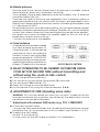
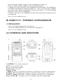
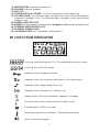
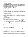
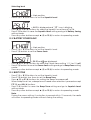
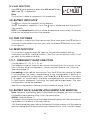
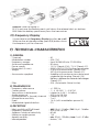
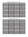
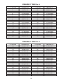
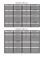
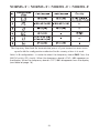
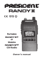
Portable P or Mobile M CB Radio Owner’s manual SUMMARY 4 6 6 7 8 13 14 14 14 17 18 ~ 20 21 RANDY II M - MOBILE CONFIGURATION RANDY II P - PORTABLE CONFIGURATION CONTROL AND FUNCTION LCD ICONS INDICATOR FUNCTION DESCRIPTION TECHNICAL CHARACTERISTICS TROUBLE SHOOTING HOW TO TRANSMIT OR RECEIVE A MESSAGE GLOSSARY CERTIFICATE OF CONFORMITY FREQUENCY TABLES NORMS - F Contents: M P Mobile Configuration Portable Configuration Rubber antenna Lithium-ion rechargeable Battery Adapter with CB antenna connector and cigarette lighter plug and Owner’s manual Wall charger and Owner’s manual 3 M ONLY WARNING! Before using, be careful never to transmit without first having connected the antenna (connection situated on the adapter) or without having set the SWR (Standing Wave Ratio) ! Failure to do so may result in destruction of the power amplifier, which is not covered by the guarantee. MULTI-NORMS TRANSCEIVER! See function “F” on page 12 and the Norms - F table on page 21. The guarantee of this transceiver is valid only in the country of purchase. Welcome to the world of the new generation of CB radios. The new PRESIDENT range gives you access to top performance CB equipment. With the use of up-to-date technology, which guarantees unprecedented quality, your PRESIDENT RANDY II is a new step in personal communication and is the surest choice for the most demanding of professional CB radio users. To ensure that you make the most of all its capacities, we advise you to read carefully this manual before installing and using your PRESIDENT RANDY II. A)RANDY II M - MOBILE CONFIGURATION 1)INSTALLATION - Connect the antenna cable to the antenna connector from the adapter. - Plug the cigarette lighter plug in the cigarette lighter socket of the car. - Clip the adapter on the device. See page 12. 2)ANTENNA INSTALLATION a)Choosing your antenna - For CB radios, the longer the antenna, the better its results. Your dealer will be able to help you with your choice of antenna. 4 b)Mobile antenna - Must be fixed to the vehicle where there is a maximum of metallic surface (ground plane), away from windscreen mountings. - If you already have a radio-telephone antenna installed, the CB antenna should be higher than this. - There are two types of antenna: pre-regulated which should be used on a good ground plane (e.g. car roof or lid of the boot), and adjustable which offer a much larger range and can be used on a smaller ground plane (see § 4, Adjustment of SWR). - For an antenna which must be fixed by drilling, you will need a good contact between the antenna and the ground plane. To obtain this, you should lightly scratch the surface where the screw and tightening star are to be placed. - Be careful not to pinch or flatten the coaxial cable (as this runs the risk of break down and/or short-circuiting). - Connect the antenna to the adapter. c)Fixed antenna - A fixed antenna should be installed in a clear a space as possible. If it is fixed to a mast, it will perhaps be necessary to stay it, according to the laws in force (you should seek professional advice). All PRESIDENT antennas and accessories are designed to give maximum efficiency to each CB radio within the range. OUTPUT RADIUS PATTERN 3)BASIC OPERATIONS TO BE CARRIED OUT BEFORE USING YOUR SET FOR THE FIRST TIME (without transmitting and without using the «push-to-talk» switch) a)Check the antenna connections. b)Turn the set on by turning the Power knob (12) clockwise. c) Turn the squelch SQ knob (4) OFF. d)Adjust the volume to a comfortable level. e) Go to channel 20 by using the channel selectors (5 & 8). 4)ADJUSTMENT OF SWR (Standing wave ratio) WARNING: This must be carried out when you use your CB radio for the first time (and whenever you re-position your antenna). The adjustment must be carried out in an obstacle-free area. * Adjustment with external SWR-meter (e.g. TOS-1 PRESIDENT) a)To connect the SWR meter: - Connect the SWR meter between the CB radio and the antenna as close as possible to the CB (use a maximum of 40 cm cable, type President CA 2C). b)To adjust the SWR meter: - Set the CB to channel 20. - Put the switch on the SWR-meter to position CAL (calibration). 5 - Press the «push-to-talk» switch on the microphone to transmit. - Bring the index needle to by using the calibration key. - Change the switch to position SWR (reading of the SWR level). The reading on the Meter should be as near as possible to 1. If this is not the case, re-adjust your antenna to obtain a reading as close as possible to 1. (An SWR reading between 1 and 1.8 is acceptable). - It will be necessary to re-calibrate the SWR meter after each adjustment of the antenna. Your CB is now ready for use. B) RANDY II P - PORTABLE CONFIGURATION 1)INSTALLATION - Screw the rubber antenna on the device. - Clip a full charged battery on the device. See page 12. Your CB is now ready for use. C)CONTROLS AND FUNCTIONS 1) ANTENNA: TNC type connector 2) PTT: “Push to Talk”switch 3) F: multi functions button 4)SQ: Squelch On/Off 5) Lock / Down / MENU: Key lock / Decrease a channel / Enter MENU when F is held-pressed. 6) SCAN / A/F / Sc. list: Scan function / AM/FM / Edit the Scan Channel List 7) DW/ P / Lamp: Dual Watch / Priority Emergency channel / LCD backlight 8) H/L / UP s / RB : TX power switch / Increase Channel / Roger Beep 6 9)MICROPHONE: Internal microphone 10) SPEAKER: Internal speaker 11) BELT CLIP 12) POWER SWITCH & VOLUME: On/Off setting and volume adjusting 13) LED INDICATOR: The indicator lights up red when transmitting and battery capacity (Voltage) is low. The indicator lights up green when receiving or squelch is off. 14) BATTERY/ADAPTER LOCK 15) BATTERY (on P portable configuration) / Adapter (on M mobile configuration) 16) EXTERNAL MICROPHONE JACK 17) EXTERNAL SPEAKER JACK 18) CHARGING INPUT (on P portable configuration) D)LCD ICONS INDICATOR Showing working channel (CH.01) or operating country mode Showing the AM or FM mode Appears when keypad is locked Appears when the channel selected is in the scanning list Appears when Roger Beep Tone is on Appears when Emergency Channel is on Battery level, showing the battery capacity (voltage) Showing transmitter output power (H=high, L=low) Indicating the “MENU” function Receiving signal level indicator / transmitting indicator Show Rx receiving signal 7 E) FUNCTION DESCRIPTION 1)ON/OFF – VOLUME -Turn On/Off-Volume knob (12) clockwise for setting the unit on and increase the volume. Every time the radio is switched on, the display will show the active band for 3 seconds. Turn On/Off-Volume knob (12) anticlockwise for decreasing the volume and setting the unit off. 2)CHANNEL SELECTOR: s / t keys -Press t (5) or s (8) button to decrease or increase a channel. 3)KEY LOCK -Press t (5) more than 3 seconds for setting the Key lock on or off. - When key lock is on, the icon is displayed and all keys are locked except PTT (2). 4)DISPLAY BACK LIGHT -Pressing F (3) + P (7) buttons to set the display backlight on or off. - When the display backlight is set on, the lightning time is 10 seconds. - Every time a button is pressed, except PTT (2), the lightning time is for more 10 seconds, 5)SCAN FUNCTION 5.1 Scan Channel List Before operating the scan function, users have to edit one channel, besides the default priority channel, in scan list. Channels at scan list are marked with “ ” icon on the display. The channels at the scanning list are scanned when scanning and the “ ” icon blink. 5.2 Adding a channel to the scanning list - Select a channel with s or t button to choose the channel that you want set. -Press F (3) + A/F (6) buttons to add the channel to scan list. - The channel is the list have a “ ” icon displayed. 5.3 Deleting a channel from the scanning list - Select a channel with s or t button. -Press F (3) + A/F (6) buttons to delete the channel from the list. The “ disappears. ” icon 5.4 Scanning On/Off -Press A/F (6) button more than 3 seconds for begin to scan. The transceiver start to scroll through the channels in scan list (the “ ” icon start blinking). It could scan minimum 5 channels per second. - When signal received, it will stop at that channel and you can hear voice from speaker. When signal disappears, it will continue to scan after 5 seconds. 8 - If there is no channel (besides the priority channel) in the list the scanning is not be able to be set on. -Press A/F(6) button 3 seconds again to stop the scan, the radio go back to the previous channel before scanning started. Note: During the scanning, if P (7) is pressed, it will stop scanning and go to the priority channel. 6)PRIORITY EMERGENCY CHANNEL “CH 19” is emergency channel for this operating mode. -Press P (7) button to go to the priority channel. The display will show “ ” icon. -Press P (7) again to quit the emergency channel and go back to the operating channel before entering into priority channel. -Press s (5) / t (8) button, it will go the previous or next channel to the priority channel. NOTE: When operating in emergency channel, the scan function would be disable. 7)MONITOR FUNCTION This function is used to setting the speaker level. - Press and hold the SQ (4) button for deactivate the squelch, you can hear the noise from speaker. - Turn Volume knob to the suitable level. -the Monitor function is active once you release the SQ (4) button. 8)RECEIVING AND TRANSMITTING 8.1 TRANSMITTING MODE -Pressing PTT (2) button to transmit. The LED lights up red and icon is displayed. one bar = 0.5-1 watt = low power two bars = 2-3 watt = high power AM four bars = > 4 watt = high power FM 8.2 RECEIVING MODE The LED lights up green in receiving mode. You can ear the signal on the and icons are displayed. speaker. 9)AM/FM MODE SETTING There are two operating mode, AM and FM. -Press A/F (6) button to alternate AM or FM mode. “AM” or “FM” icon is displayed. 10) TRANSMITTING POWER -Press s (8) 3 seconds (or more) to select transmitting output power. FM: L = 1W, H = 4W / AM: L = 1W, H = 3W. Every long press alternate the power level. “H” or “L” is displayed. 9 11) ROGER BEEP This function is used to remind the partner, when the TX is off (PTT button is released), the radio will beep to confirm to other users that your transmission has finished. -Press F (3) + s (8) buttons to turn the ROGER BEEP tone on, “ ” icon is displayed. -Press F (3) + s (8) buttons to turn off this function, “ ” icon disappears. 12) DUAL WATCH (SCAN) This function is used to scan the operating channel and “Priority Emergency Channel”. -Press P (7) button 3 seconds to set this function on, “d” and “ ” icon are displayed. - The radio will be scanning between the operating channel and “Priority Emergency Channel”. -Press P (7) button again 3 seconds to quit this mode, it will go to the previous operating channel.“d” and “ ” icon disappears. Note: During this mode, the radio will stop at the channel that has signal. And when the signal disappears, it will go back to dual watch mode after 5 seconds. During this mode, if PTT (2) pressed, the radio transmitting at that channel. When PTT (2) released, it will go back to dual watch mode. When SQ (4) pressed, it will have noise from the speaker even if there is no signal. During this mode, except PTT (2), SQ (4) and P (7), other buttons will be disable, and it will have error sound when they are pressed. 13) MENU FUNCTION This is multi function of system setting. Press F (3) + t (5) buttons to enter into the setting menu, “M” icon is displayed. -Press F (3) button to choose the desired setting item. There are three items who could be set in this menu: SQ level, battery saving and beep tone. -Press s (5) or t (8) to do the setting. -press F to store and go to next setting item. - Press any other button except s (5) or t (8) to return to the operating mode. 13.1 SQUELCH LEVEL It is possible to set the different squelch levels for the radio. The selected level setting is for all programmed channels. Selectable levels: 0 (oF) ~ 6 Note: The squelch level setting directly controls the receiver. Before storing the level it is possible to hear that the squelch is closed. This is very useful for determining the level for the radio before storing it. 10 Selecting level > Start position -Press F (3) + t (5) buttons to set the Squelch Level. > SL 01 is displayed and “Sq ” icon is blinking. -Press s (5) or t (8) buttons for selecting Squelch Level from oF to 06. -Press F (3) button to save the Squelch Level setting and go to Battery Saving setting mode. - Press any other button except s (5) or t (8) to return to operating mode. 13.2 BATTERY POWER SAVE > Start position -Press F (3) + t (5) buttons to set the Squelch Level. -Press F (3) button to set the Power Save. > PS 01 and are displayed. -Press s (5) or t (8) buttons for selecting Power Save setting 1, 2, 3 or 0 (=off) -Press F (3) button to save the Power Save setting and go to Beep Tone setting mode. - Press any other button except s (5) or t (8) to return to operating mode. 13.3 BEEP TONE -Press F (3) + t (5) buttons to set the Squelch Level. -Press F (3) button two times to set the Beep Tone. -Press s (5) or t (8) buttons for setting the Beep Tone on or off. When Beep Tone is on, a beep tone is heard when a button is pressed except PTT (2) and SQ (4) buttons. -Press F (3) button to save the Beep Tone setting and go to Squelch Level setting mode. - Press any other button except s (5) or t (8) to return to operating mode. Note: During the menu setting, if no button is pressed within 10 seconds, the radio will return to operating mode without storing the setting. 11 13.4 ANL FUNCTION -Press SQ (4) and release to alternate ANL on/off. When ANL is on “AL" is displayed. Note: This function is able to operate in AM mode only. 14) BATTERY INDICATOR The icon shows the capacity of the battery. When the battery capacity is low, the icon is displayed and the red LED start to blink. NOTE: If the Beep Tone function is set on, a beep tone warns every 10 second, otherwise no beep tone from the speaker. 15) TIME OUT TIMER This function is used to limit the transmission time when press the PTT button, it stop transmission after times out, you have to release PTT button if you want to re-transmit. 16) RESET FUNCTION This function is used to reset the radio to the previous default setting. - Hold press the t (5) + A/F (6) buttons, then turn on the power switch, it will go back to the default setting. 17) F - FREQUENCY BAND SELECTION (configuration EC, EU, In, U, PL, d) The frequency bands have to be chosen according to the country of use. Don’t use any other configuration. Some countries need a user’s licence. See table page 22. - Proceeding: switch off the transceiver. Press the F (3) button during the radio is switched on. The letter corresponding to the configuration is blinking. In order to change the configuration, use the s (5) or t (8) buttons. Then press F (3) again. As confirmation, the letter corresponding to the configuration is continuously displayed. Switching the radio off and on again, the new configuration would be enabled. See the configurations/ frequency bands table at page 18 to 20. 18) BATTERY PACK/ADAPTER ATTACHMENT AND REMOVAL Note: Because the battery pack is provided uncharged, you must charge the battery pack before using it with the transceiver. INSTALL (See the figure 1) 1-1: Match the four grooves at the edge of battery pack with the corresponding guides on the back of the transceiver. 1-2: Slide the battery pack along the back of the transceiver until the release latch on the base of the transceiver locks. Meanwhile, a “click” sound is heard. 12 REMOVE (See the figure 2) 2-1: To remove the battery pack, pull down the release latch on bottom. 2-2: Slide the battery pack away form the transceiver. 19) Frequency Display It is possible to set Frequency Display function on or off. When active, at standby mode, press F (3) button shows the frequency of the channel. F) TECHNICAL CHARACTERISTICS 1)GENERAL -Channels :40 - Modulation modes : AM / FM - Frequency ranges : from 26.965 MHz to 27.405 MHz - Antenna impedance : 50 ohms - Power supply : 13.2 V (Randy II M) / 7.4 V (Randy II P) - Dimensions (in mm) : 54 (W) x 35 (D) x 120 (H) without accessories - Weight : 319 g with accessories (Randy II M) 357 g with accessories (Randy II P) - Accessories supplied : Adapter with antenna connector and cigarette lighter plug (Randy II M) Battery, rubber antenna and wall charger (Randy II P) - Filter : ANL (Automatic Noise Limiter) 2)TRANSMISSION - - - - - - - - Frequency allowance Carrier power Transmission interference Audio response Emitted power in the adj. channel Microphone sensitivity Drain Modulated signal distortion : : : : : : : : +/- 200 Hz 1 ~ 3 W AM / 1 ~ 4 W FM inferior to 4 nW (- 54 dBm) 300 Hz to 2.5 KHz inferior to 20 µW 7 mV 1,8 A (with modulation power Hi) 2% : : : : : : AM: 0.5 µV - 113 dBm / FM : 0.3 µV - 116 dBm 300 Hz to 2.5 kHz 60 dB 1W min : 0.2 µV - 120 dBm / max : 1 mV - 47 dBm 8 ohms, 1 W 3)RECEPTION - - - - - - Maxi. sensitivity at 20 dB sinad Frequency response Adjacent channel selectivity Maximum audio power Squelch sensitivity Internal speaker 13 G) TROUBLE SHOOTING 1) YOUR CB RADIO WILL NOT TRANSMIT OR YOUR TRANSMISSION IS OF POOR QUALITY - Check that the antenna is correctly connected. - Check that the SWR is properly adjusted (RANDY II M - Mobile Option only). - Check that the programmed configuration is the correct one (see table page 21). 2) YOUR CB RADIO WILL NOT RECEIVE OR RECEPTION IS POOR - Check that the squelch level is properly adjusted. - Check that the programmed configuration is the correct one (see table page 21). - Check that the volume is set to a comfortable listening level. - Check that the antenna is correctly connected. - Check that the SWR is properly adjusted (RANDY II M - Mobile Option only). - Check that you are using the same modulation mode as your correspondent. 3)YOUR CB WILL NOT LIGHT UP - Check the battery or power supply. - Check the connection wiring. - Check the fuse (RANDY II M - Mobile Option only). H) HOW TO TRANSMIT OR RECEIVE A MESSAGE Now that you have read the manual, make sure that your CB Radio is ready for use (i.e. check that your antenna is connected). Choose your channel (19, 27). Choose your mode (AM/FM) which must be the same as that of your correspondent. Press the «push-to-talk» switch and announce your message «Attention stations, transmission testing» which will allow you to check the clearness and the power of your signal. Release the switch and wait for a reply. You should receive a reply like, «Strong and clear». If you use a calling channel (19, 27) and you have established communication with someone, it is common practice to choose another available channel so as not to block the calling channel. I) GLOSSARY Below you will find some of the most frequently used CB radio expressions. Remember this is meant for fun and that you are by no means obliged to use them. In an emergency, you should be as clear as possible. 14 INTERNATIONAL PHONETIC ALPHABET AAlpha HHotel OOscar BBravo IIndia PPapa CCharlie JJuliett QQuebec DDelta K Kilo RRomeo EEcho L Lima S Sierra FFoxtrott MMike TTango GGolf NNovemberUUniform VVictor WWhiskey XX-ray YYankee ZZulu TECHNICAL VOCABULARY AM CB CH CW DX DW FM GMT HF LF LSB RX SSB SWR SWL SW TX UHF USB VHF : Amplitude Modulation : Citizen’s Band : Channel : Continuous Wave : Long Distance Liaison : Dual Watch : Frequency Modulation : Greenwich Meantime : High Frequency : Low Frequency : Lower Side Band : Receiver : Single Side Band : Standing Wave Ratio : Short Wave Listening : Short Wave : CB Transceiver : Ultra High Frequency : Upper Side Band : Very High Frequency CB LANGUAGE Advertising Back off Basement Base station Bear Bear bite Bear cage Big slab Big 10-4 Bleeding Blocking the channel Blue boys : Flashing lights of police car : Slow down : Channel 1 : A CB set in fixed location :Policeman : Speeding fine : Police station : Motorway : Absolutely : Signal from an adjacent channel interfering with the transmission : Pressing the PTT switch without talking : Police 15 Break Breaker Clean and green Cleaner channel Coming in loud and proud Doughnut Down and gone Down one Do you copy? DX Eighty eights Eye ball Good buddy Hammer Handle Harvey wall banger How am I hitting you? Keying the mike Kojac with a kodak Land line Lunch box Man with a gun Mayday Meat wagon Midnight shopper Modulation Negative copy Over your shoulder Part your hair Pull your hammer back Rat race Rubberbander Sail boat fuel Smokey dozing Smokey with a camera Spaghetti bowl Stinger Turkey Up one Wall to wall What am I putting to you? : Used to ask permission to join a conversation : A CBer wishing to join a channel : Clear of police : Channel with less interference : Good reception :Tyre : Turning CB off : Go to a lower channel : Understand? : Long distance : Love and kisses : CBers meeting together : Fellow CBer :Accelerator : CBer’s nickname : Dangerous driver : How are you receiving me? : Pressing the PTT switch without talking : Police radar : Telephone : CB set : Police radar :SOS : Ambulance : Thief :Conversation : No reply : Right behind you : Behave yourself - police ahead : Slow down : Congested traffic : New CBer : Wind : Parked police car : Police radar : Interchange :Antenna : Dumb CBer : Go up one channel : All over/everywhere : Please give me an S-meter reading. 16 CERTIFICATE OF CONFORMITY We, GROUPE PRESIDENT ELECTRONICS, Route de Sète, BP 100 – 34540 Balaruc – FRANCE, declare, on our own responsibility that the CB radio-communication transceiver Brand : PRESIDENT Model : RANDY II Manufactured in Taiwan is in conformity with the essential requirements of the Directive 1999/5/CE (Article 3) adapted to the national law, as well as with the following European Standards: EN 300 433-1 V1.3.1 (2011-07) EN 300 433-2 V1.3.1 (2011-07) EN 301 489-1 V1.8.1 (2010-1) EN 301 489-13 V1.2.1 (2002-8) EN 60215 (1996) Balaruc, the 2012-09-03 Jean-Gilbert MULLER General Manager 17 FREQUENCY TABLE for EU / EC / U (CEPT) Channel 1 2 3 4 5 6 7 8 9 10 11 12 13 14 15 16 17 18 19 20 Frequency 26,965 MHz 26,975 MHz 26,985 MHz 27,005 MHz 27,015 MHz 27,025 MHz 27,035 MHz 27,055 MHz 27,065 MHz 27,075 MHz 27,085 MHz 27,105 MHz 27,115 MHz 27,125 MHz 27,135 MHz 27,155 MHz 27,165 MHz 27,175 MHz 27,185 MHz 27,205 MHz Channel Frequency 21 22 23 24 25 26 27 28 29 30 31 32 33 34 35 36 37 38 39 40 27,215 MHz 27,225 MHz 27,255 MHz 27,235 MHz 27,245 MHz 27,265 MHz 27,275 MHz 27,285 MHz 27,295 MHz 27,305 MHz 27,315 MHz 27,325 MHz 27,335 MHz 27,345 MHz 27,355 MHz 27,365 MHz 27,375 MHz 27,385 MHz 27,395 MHz 27,405 MHz FREQUENCY TABLE for U (ENG) Channel Frequency 27,60125 MHz 27,61125 MHz 27,62125 MHz 27,63125 MHz 27,64125 MHz 27,65125 MHz 27,66125 MHz 27,67125 MHz 27,68125 MHz 27,69125 MHz 27,70125 MHz 27,71125 MHz 27,72125 MHz 27,73125 MHz 27,74125 MHz 27,75125 MHz 27,76125 MHz 27,77125 MHz 27,78125 MHz 27,79125 MHz 1 2 3 4 5 6 7 8 9 10 11 12 13 14 15 16 17 18 19 20 Channel Frequency 21 22 23 24 25 26 27 28 29 30 31 32 33 34 35 36 37 38 39 40 18 27,80125 MHz 27,81125 MHz 27,82125 MHz 27,83125 MHz 27,84125 MHz 27,85125 MHz 27,86125 MHz 27,87125 MHz 27,88125 MHz 27,89125 MHz 27,90125 MHz 27,91125 MHz 27,92125 MHz 27,93125 MHz 27,94125 MHz 27,95125 MHz 27,96125 MHz 27,97125 MHz 27,98125 MHz 27,99125 MHz FREQUENCY TABLE for d Channel 1 2 3 4 5 6 7 8 9 10 11 12 13 14 15 16 17 18 19 20 Frequency Channel Frequency 26,965 MHz 2127,215 MHz 26,975 MHz 2227,225 MHz 26,985 MHz 2327,255 MHz 27,005 MHz 2427,235 MHz 27,015 MHz 2527,245 MHz 27,025 MHz 2627,265 MHz 27,035 MHz 2727,275 MHz 27,055 MHz 2827,285 MHz 27,065 MHz 2927,295 MHz 27,075 MHz 3027,305 MHz 27,085 MHz 3127,315 MHz 27,105 MHz 3227,325 MHz 27,115 MHz 3327,335 MHz 27,125 MHz 3427,345 MHz 27,135 MHz 3527,355 MHz 27,155 MHz 3627,365 MHz 27,165 MHz 3727,375 MHz 27,175 MHz 3827,385 MHz 27,185 MHz 3927,395 MHz 27,205 MHz 4027,405 MHz FREQUENCY TABLE for d Channel 41 42 43 44 45 46 47 48 49 50 51 52 53 54 55 56 57 58 59 60 Frequency Channel Frequency 26,565 MHz 6126,765 MHz 26,575 MHz 6226,775 MHz 26,585 MHz 6326,785 MHz 26,595 MHz 6426,795 MHz 26,605 MHz 6526,805 MHz 26,615 MHz 6626,815 MHz 26,625 MHz 6726,825 MHz 26,635 MHz 6826,835 MHz 26,645 MHz 6926,845 MHz 26,655 MHz 7026,855 MHz 26,665 MHz 7126,865 MHz 26,675 MHz 7226,875 MHz 26,685 MHz 7326,885 MHz 26,695 MHz 7426,895 MHz 26,705 MHz 7526,905 MHz 26,715 MHz 7626,915 MHz 26,725 MHz 7726,925 MHz 26,735 MHz 7826,935 MHz 26,745 MHz 7926,945 MHz 26,755 MHz 8026,955 MHz 19 FREQUENCY TABLE for PL Channel 1 2 3 4 5 6 7 8 9 10 11 12 13 14 15 16 17 18 19 20 Frequency 26,960 MHz 26,970 MHz 26,980 MHz 27,000 MHz 27,010 MHz 27,020 MHz 27,030 MHz 27,050 MHz 27,060 MHz 27,070 MHz 27,080 MHz 27,100 MHz 27,110 MHz 27,120 MHz 27,130 MHz 27,150 MHz 27,160 MHz 27,170 MHz 27,180 MHz 27,200 MHz Channel Frequency 21 22 23 24 25 26 27 28 29 30 31 32 33 34 35 36 37 38 39 40 27,210 MHz 27,220 MHz 27,250 MHz 27,230 MHz 27,240 MHz 27,260 MHz 27,270 MHz 27,280 MHz 27,290 MHz 27,300 MHz 27,310 MHz 27,320 MHz 27,330 MHz 27,340 MHz 27,350 MHz 27,360 MHz 27,370 MHz 27,380 MHz 27,390 MHz 27,400 MHz FREQUENCY TABLE for In Channel 1 2 3 4 5 6 7 8 9 10 11 12 13 14 15 16 17 18 19 20 Frequency 26,965 MHz 26,975 MHz 26,985 MHz 27,005 MHz 27,015 MHz 27,025 MHz 27,035 MHz 27,055 MHz 27,065 MHz 27,075 MHz 27,085 MHz 27,105 MHz 27,115 MHz 27,125 MHz 27,135 MHz 27,155 MHz 27,165 MHz 27,175 MHz 27,185 MHz 27,205 MHz Channel Frequency 21 22 23 24 25 26 27 20 27,215 MHz 27,225 MHz 27,255 MHz 27,235 MHz 27,245 MHz 27,265 MHz 27,275 MHz Norms - F • Norms - F • Norms - F • Norms - F The frequency band and the transmission power of your transceiver must correspond with the configuration authorized in the country where it is used. Note: In U configuration : In order to select the frequency band ENG. Press the AM/FM switch (11) shortly. When the frequency band is ENG, «UK» appears on the display. When the frequency band is CEPT, «UK» disappears from the display (see table at page 18). 21 Contries in which there are particular restrictions (licence1 / Register2) Please see updated table on website www.president-electronics.com, page «The CB radios» then «President Radio CB and Europe». 22 SIEGE SOCIAL/HEAD OFFICE - FRANCE - Route de Sète - BP 100 34540 BALARUC Site Internet : http://www.president-electronics.com E-mail : [email protected] 1289/08-12