1
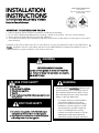
VIKING RANGE CORPORATION
111 Front Street
Greenwood, Mississippi 38930 USA
(662) 455-1200
INSTALLATION
INSTRUCTIONS
OUTDOOR GAS GRILLS VGBQ T-SERIES
Retain for Future Reference
IMPORTANT: PLEASE READ AND FOLLOW
1.
2.
3.
4.
Before beginning, please read these instructions completely and carefully.
Do not remove permanently affixed labels, warnings, or plates from product. This may void the warranty
Please observe all local and national codes and ordinances.
The installer should leave these instructions with the consumer who should retain for local inspector’s use and for
future reference
Installation must conform with local codes or in the absence of codes, the National Fuel Gas Code, ANSI Z223.1. In
Canada: Installation must be in accordance with the current CAN/CGA-B149.1, Natural Gas Installation Code or
CAN/CGA-B149.2, Propane Installation Code and/or local codes.
WARNING
EXCESSIVE WEIGHT HAZARD
Use two or more people to move and install this
unit. Failure to follow this instruction can result in
back or other injury.
FOR YOUR SAFETY
WARNING
If you smell gas:
1. Shut off gas to the appliance.
2. Extinguish any open flame.
3. Open lid.
4. If odor continues, immediately call your gas supplier or your
fire department.
If not installed, operated and maintained in
accordance with the manufacturer’s instructions, this
product could expose you to substances in fuel or
fuel combustion which can cause death or serious
illness and which are known to cause cancer, birth
defects or other reproductive harm.
For example, benzene is a chemical which is
part of the gas supplied to the cooking
product. It is consumed in the flame during
combustion. However, exposure to a small
amount of benzene is possible if a gas leak
occurs. Formaldehyde and soot are byproducts of incomplete combustion. Properly
adjusted burners with a bluish rather than
yellow flame minimize incomplete combustion.
FOR YOUR SAFETY
1. Do not store or use gasoline or other flammable vapors
and liquids in the vicinity of this or any other appliance.
2. Any LP cylinder not connected for use shall not be stored
in the vicinity of this or any other appliance.
1
BASIC SPECIFICATIONS
Description
VGBQ300T/0302T
Cutout Width
28 5/8”
40 1/4”
(72.7 cm)
(102.2 cm)
VGBQ410T/VGIQ410T
VGBQ412T
VGBQ532T/VGIQ532T
40 1/4”
52 1/4”
52 1/4”
(102.2 cm)
(132.7 cm)
(132.7 cm)
Cutout Depth
28” (71.1 cm)
Cutout Height
10 1/4” (26.0 cm)
Overall Width
VGBQ530T/VGIQ530T
29 ½”
41 3/16”
41 3/16”
53 3/16”
53 3/16”
(74.9 cm)
(104.6 cm)
(104.6 cm)
(135.1 cm)
(135.1 cm)
Overall Depth
32 3/4” (83.2 cm)
Gas
Natural:
standard residential 1/2” (1.3 cm) ID gas service line.
Requirements
LP/Propane:
equipped with high capacity hose/regulator assembly for connection to standard 5gal, 20
lb. LP/Propane gas cylinder with Type 1, QCC-1 connection or standard residential 1/2”
Electrical
Requirements
Grill Burner
(1.3 cm) ID gas service line.
9 volt DC battery for electronic ignition
120VAC/60HZ - 24” (61.0 cm) grounded plug attached to rotisserie motor
25,000 BTU Nat./22,500 BTU LP
Rating
TruSearTM Burner
Rating
Smoker Burner
Rating
(If applicable)
Side Burner
Rating
(If applicable)
Rotisserie Burner
Rating
(If applicable)
(4.4 kW Nat./4.0 kW LP)
Approximate
Shipping Weight
325 lbs.
(147 kg)
N/A
(7.3 kW Nat./6.5 kW LP)
30,000 BTU Nat/LP
N/A
8.8 kW Nat./LP
12,500 BTU Nat./10,500 BTU LP
(3.7 kW Nat./3.1 kW LP)
30,000 BTU Nat./LP
8.8 kW Nat./LP
15,000 BTU Nat./13,500 BTU LP
(4.4 kW Nat./4.0 kW LP)
(1) 15,000 Nat./
13,500 LP
(1) 15,000 Nat./
13,500 LP
(4.4 kW Nat./4.0 kW LP)
380 lbs.
(172 kg)
(1) 15,000 Nat./
13,500 LP
(2) 15,000 Nat./
13,500 LP
(1) 15,000 Nat./
13,500 LP
(4.4 kW Nat./4.0 kW LP)
(4.4 kW Nat./4.0 kW LP)
(4.4 kW Nat./4.0 kW LP)
350 lbs.
(159 kg)
2
490 lbs.
(222 kg)
460 lbs.
(209 kg)
GENERAL INFORMATION
WARNING: This outdoor gas grill is not intended to be installed in or on recreational vehicles and/or
1.
boats.
2.
WARNING:
Keep electrical supply cord and the fuel supply hose away from heated surfaces.
3. Keep grill area clear and free from combustible materials, gasoline, and other flammable vapors.
4. When the outdoor grill is not in use, the gas supply must be turned off at the LP gas supply cylinder.
5. The pressure regulator and hose assembly supplied with the outdoor grill must be used. Replacement pressure
regulators and hose assemblies must be those specified by the manufacturer.
6. Finding a leak is not a “do-it-yourself” procedure. Some leaks can only be found with the burner control in the on
position and this must be done by a qualified technician.
7. The LP supply cylinder to be used must be constructed and marked in accordance with the specifications for LPgas cylinders of the U.S. Department of Transportation (DOT) or the National Standard of Canada, CAN/CSA-B339,
Cylinders, Spheres, and Tubes for the Transportation of Dangerous Goods.
8. Gas Manifold Pressure Natural gas - 4.0” W.C.P.
LP/Propane - 10.0” W.C.P.
9. If the following instructions are not followed exactly, a fire causing death or serious injury may occur:
-Do not store a spare LP gas cylinder under or near this appliance.
-Never fill the cylinder beyond 80 percent full.
GAS CONNECTION
Verify the type of gas supply to be used, either natural or LP, and make sure the marking on the grill rating
plate agrees with that of the supply. Never connect an unregulated gas line to the appliance. An installer supplied gas
shut-off valve must be installed in an easily accessible location. All installer supplied parts must conform to local codes,
or in the absence of local codes, with the National electrical Code, ANSI/NFPA 70 and the National Fuel Code, ANSI
Z223.1. In Canada: Installation must be in accordance with the current CAN/CGA-B149.1, Natural Gas Installation
Code or CAN/CGA-B149.2, Propane Installation Code and/or local codes. All pipe sealants must be an approved type
and resistant to the actions of LP gas. Never use pipe sealant on flare fittings. All gas connections should be made by
a competent technician and in accordance with local codes and or ordinances. In the absence of codes, the installation
must comply with the National Fuel Gas Code ANSI Z223.1.
The gas grill and its individual shut-off valve must be disconnected from the gas supply piping system during
any pressure testing of that system at test pressures in excess of 1/2 PSIG (3.5 kPa). The gas grill must be isolated from
the gas supply piping system by closing its individual manual shut-off valve during any pressure testing of that sysptem
at test pressures equal to or les than 1/2 psi (3.5 kPa).
GAS CONVERSION
To convert a grill from natural to LP/Propane or LP/Propane to natural, you MUST use the conversion kit
supplied by the manufacturer.
WARNING:
Conversions should only be done by an authorized service technician.
3
NATURAL FIXED PIPING CONNECTION
Connection:
Operating Pressure:
Supply Pressure:
Standard Residential 1/2” ID gas service line - 1/2” NPT male with 7/8” (2.2 cm) flare adapter.
4.0” W.C.P. Nat.
6” to 14” W.C.P. Nat. If in excess of 14” W.C.P., a step-down regulator is required.
Check with your local gas utility company or with local codes for instructions on installing gas supply lines. Be sure to check on
type and size of run and how deep to bury the lines. If the gas line is too small, the grill will not function properly.
To connect the supplied regulator assembly to the incoming flexible gas line, attach with a 1/2” (1.3 cm) female flare adaptor
to the 7/8” (2.2 cm) male flare adaptor on the regulator assembly. Ensure that the regulator arrow points in the direction of the
gas flow towards the unit and away from the supply. Attach the regulator assembly to the grill unit by pulling back the female
coupler sleeve towards the regulator. Insert the coupler into themale coupler fitting on the grill until the sleeve snaps forward
securing the connection. DO NOT forget to place the installer supplied gas valve in an accessible location.
NOTE: If using a Viking GSH12 flexible hose, remove the 1/2” flare adapter and attach hose to the the 7/8” (2.2 cm) male
flare on the regulator assembly.
Female
coupler sleeve
Regulator
Male
coupler
fitting
7/8” male
flare adaptor
Regulator Assembly
Installer supplied flexible
gas line with 1/2”
female flare adaptor or
Viking GSH12
4
LP/PROPANE FIXED PIPING CONNECTION
Connection:
Operating Pressure:
Supply Pressure:
Standard Residential 1/2” ID gas service line - 1/2” NPT male with 3/8” flare adapter.
10.0” W.C.P. Nat.
11” to 14” W.C.P. Nat. If in excess of 14” W.C.P., a step-down regulator is required.
Check with your local gas utility company or with local codes for instructions on installing gas supply lines. Be sure to check on
type and size of run and how deep to bury the lines. If the gas line is too small, the grill will not function properly.
To connect the supplied regulator assembly to the incoming flexible gas line, attach with a 3/8” female flare adaptor to the
3/8” male flare adaptor to the regulator assembly. Ensure that the regulator arrow points in the direction of the gas flow
towards the unit and away from the supply. Attach the regulator assembly to the grill unit with the 3/8” flemale flare adapter
on the regulator assembly to the 3/8” male flare adaptor on the grill.
DO NOT forget to place the installer supplied gas valve in an accessible location.
3/8” female
flare adaptor
Regulator
3/8” Male
flare
adaptor
3/8” male
flare adaptor
Regulator Assembly
Installer supplied flexible
gas line with 3/8”
female flare adaptor or
Viking GHS12
5
LP/Propane Tank Connection
Outdoor grills orificed for use with LP/Propane gas come equipped with a high capacity hose/regulator assembly for
connection to a standard 20 lb. LP/Propane cylinder equipped with a Type 1, QCC-1 connector. (See LP/Propane tank
requirements on page 6).
Connection: 1/2” (1.3 cm) NPT male with a 3/8” (.95) flare adapter
Operating Pressure: 10.0” W.C.P.
To connect to LP/Propane regulator/hose assembly:
Although the flow of gas is stopped when the quick disconnect system is disconnected as part of its safety feature,
you should always turn the LP/Propane tank main valve “OFF” after each use and during transport of the tank or
unit. First connect the regulator to the grill unit by screwing the 3/8” flare coupling ot the 3/8” flare adaptor.
Connect to the tank valve by screwing the Type 1, QCC-1 connector to the LP/Propane tank. Open the tank valve
and check the connection between the regulator and the Type 1, QCC-1 fitting for leaks with a soapy water
ALWAYS CHECK
solution. If bubbles appear, tighten the connection. Repeat until all leaks have been stopped.A
FOR LEAKS AFTER EVERY LP/PROPANE TANK CHANGE
Any joint sealant used must be an approved type and be resistive to the actions of LP/Propane gas
3/8” flare
adaptor
3/8” flare coupling
Type 1, QCC-1
connector
Tank
LP/Propane Tank Requirements
A dented or rusty LP/Propane tank may be hazardous and should be checked by your tank supplier. Never use a
cylinder with a damaged valve. All tanks should be equipped with an OPD (overfilling protection device). This is a DOT
requirement for all tanks purchased after October 1, 1998 and will ensure that the tank is not overfilled. The LP/Propane
tank should be a standard 5-gal, 20 lb. gas cylinder tank approximately 12” in diameter and 18” high which must be
constructed and marked in accordance with the Specifications for LP/Propane Gas Cylinders of the U.S. Department of
Transportation (D.O.T.) or the National Standard of Canada, CAN/CSA-B339, Cylinders, Spheres and Tubes for
Transportation of Dangerous Goods; and Commission. The cylinder connection device must be compatible with the Type
1, QCC-1 connector on the outdoor cooking appliance. The cylinder must be provided with a shut-off valve terminating in
an LP/Propane gas supply cylinder valve outlet specified. The cylinder supply system must be arranged for vapor
withdrawal and provided with a listed overfilling prevention device. If the appliance is stored indoors the cylinder must be
disconnected and removed from the appliance. Cylinders must be stored outdoors in a well-vented area out of the reach
of children.
6
LEAK TESTING
Although all gas connections on the grill are leak tested at the factory prior to shipment, a complete gas tightness
check must be performed at the installation due to possible mishandling in shipment or excessive pressure unknowingly being
applied to the unit. Periodically check the whole system for leaks, or immediately check if the smell of gas is detected.
1. Do not smoke while leak testing. Extinguish all flames.
2. Never leak test with an open flame.
3. Make a soap solution of one part liquid detergent and one part water. You will need a spray bottle, brush or towel to apply
the solution to the fittings. For LP/Propane units, check with a full cylinder.
4. Check that all control knobs are in the “OFF” position.
5. Turn cylinder valve knob counter clockwise one turn to open.
6. Blowing bubbles in the soap solution indicates that a leak is present.
7. Stop a leak by tightening the loose joint or by replacing the faulty part with a replacement part recommended by the
manufacturer. Do not attempt to repair the cylinder valve if it should become damaged. The cylinder must be replaced.
8. If you are unable to stop a leak, shut off the gas supply at the cylinder valve. Remove the cylinder from the grill. Call an
authorized gas appliance service technician or LP/Propane gas dealer. Do not use the grill until the leak is corrected.
9. After checking for leaks, push in and turn any control knob to release the pressure in the hose and manifold. Turn off the
control knob.
CAUTION
Before placing into operation, always check for gas leaks with a soapy
water solution. DO NOT USE AN OPEN FLAME TO CHECK FOR LEAKS!
LEAK TEST
POINTS
7
INSTALLATION PROCEDURES FOR BUILT-IN INSTALLATION
1. A minimum of 6” (15.2 cm) from the sides, or a minimum of 8” (20.3 cm) from the right side if there is a rotisserie motor,
and a minimum of 24” (61.0 cm) from the back must be maintained from the grill above the cooking surface to adjacent
vertical combustible construction. The grill is not to be located under overhead unprotected combustible construction.
2. A minimum of 3” (7.6 cm) clearance from the back of the grill with a canopy and a minimum of 6” (15.2 cm) from the back
of the grill without a canopy to non-combustible construction is required for the purpose of allowing the lid to open fully
and for proper ventilation. Note that the grill exhausts combustion products and cooking greases to the back. Never locate
the grill in a location where the exhaust is directed at a window, less than 24” (61.0 cm) to combustible material or any
surface that is difficult to clean. It is desirable to allow at least 6” side clearance to non-combustible construction above the
cooking surface for counter space. If using the rotisserie option, the space is essential for motor and skewer clearance. The
grill can be placed directly adjacent to combustible and/or non-combustible construction below the cooking surface.
3. When determining a suitable location for the grill, take into account concerns such as exposure to wind, proximity to traffic
paths and keeping gas supply lines as short as possible. Locate the grill only in a well-ventilated area. Never locate the grill
in a building, garage, breezeway, shed or other such enclosed areas. During heavy use, the grill will produce a lot of smoke.
Ensure there is adequate area for it to dissipate.
4. If using a rear wall, locate the electrical service on the right hand side for the rotisserie motor. The rotisserie motor requires
a 110/120 volt supply. the power supply cord on the motor is equipped with a 3-prong (grounded) plug for protection
against shock hazard. Do not cut or remove the grounding from the plug. The electrical service must be equipped with a
properly grounded 3-prong receptacle as required by the National Electrical Code ANSI/NFPA 70-latest edition. Installation
in Canada must be in accordance with the Canadian Electrical Code, CSA 22.1 and local codes.
IMPORTANT: Gas fittings, regulator, and installer supplied shut-off valve must be easily accessible.
8
Built-In Clearance Dimensions
32 3/4” (83.2 cm)
31 9/16” (80.2 cm)
Min. 3” (7.6 cm) to noncombustible surface
Min. 24” (61.0 cm) to
combustible surface
22 15/16”
(58.3 cm)
16 5/8”
(42.4 cm)
10 1/4”
(26.0 cm)
6”
(15.2 cm)
A
8” (20.3 cm)*
5 3/8” (13.7 cm)
10 9/16”
(26.8 cm)
*Minimum clearance
needed for removal and
replacement of Rotisserie
Motor.
MODEL
Dim. A
VGBQ300T/0302T
29 1/2”
(74.9 cm)
VGBQ410T/VGIQ410T
41 3/16”
(104.6 cm)
VGQB412T
41 3/16”
(104.6 cm)
9
VGBQ530T/VGIQ530T
53 3/16”
(135.1 cm)
VGBQ532T/VGIQ532T
53 3/16”
(135.1 cm)
Cutout Dimensions
28” (71.1 cm)
B
**Gas Inlet can be
located anywhere
within 5” (12.7 cm)
shaded area
5”
(12.7 cm)
**
36”
(91.4 cm)
5”
(12.7 cm)
Electrical Connection for
Rotisserie Motor
(position unit so that the
plug is always accessible)
Min. 3”
(7.6 cm)
***Solid
Bottom
Support
10 1/4”
(26.0 cm)
*Access
Door
Opening
*Access Doors sold separately refer to access door installation
instructions for correct dimensions
***Important: Cabinet cutout must have a
solid bottom to support the full weight
of the unit.
Model
VGBQ300T/0302T
VGBQ410T/VGIQ410T
VGBQ412T
VGBQ530T /VGIQ530T
VGBQ532T/VGIQ532T
10
Dim. B
28 5/8” (72.7 cm)
40 1/4” (102.2 cm)
40 1/4” (102.2 cm)
52 1/4” (132.7 cm)
52 1/4” (132.7 cm)
BURNER ADJUSTMENT
Each burner is tested and adjusted at the factory prior to shipment; however, variations in the local gas supply may
make it necessary to adjust the burners. The flames of the burners (except the rotisserie infrared burner) should be visually
checked and compared with Fig. 1, Fig. 2, and Fig. 3.
Flames should be blue and stable with no yellow tips, excessive noise or lifting. If any of these conditions exist, check
if the air shutter or burner ports are blocked by dirt, debris, spider webs, etc. With a proper flame height, adjust the air shutter
to obtain a blue flame with no yellow tipping that sits on the burner at the burner ports. The air shutter is locked in place by a
set screw which must be loosened prior to lighting the burner for adjustments.
To access the air shutter on the grill burners and smoker burner, remove the valve panel. To access the air shutter on
the side burners, remove the grates, burner bowls, and grate support. With a screw driver, loosen the lock-screw on the face
of the air shutter. Light the burner and adjust according to the directions below.
1. If the flame is yellow, turn the air shutter counter clockwise to allow more air to the burner.
2. If the flame is noisy and lifting away from the burner, turn the air shutter clockwise to reduce the amount of air to
the burner.
Once adjusted, turn the burner off, tighten the set screw on the air shutter, replace the valve panel for the grill burners and the
grate support, burner bowls, and grates for the side burners.
To ensure proper installation of the grill burners, side burners, and smoker burner:
1. Slide opening in air shutters over the orifice located in the front of the grill.
2. For the smoker burner, secure back of the burner by placing over screw slot on rear of grill and replacing screw.
Fig. 1
GRILL BURNER
1/2”
(1.3 cm)
3/8”
(.95 cm)
Orifice
Air
Shutter
3/8” (.95 cm)
1/2” (1.3 cm)
Orifice
Fig. 2
SMOKER BURNER
11
Fig. 3
SIDE BURNERS
(If applicable)
Air Shutters
Orifice
1½”
(3.8 cm)
3/8”
(.95 cm)
Fig. 4
FLAME HEIGHT
SIDE BURNERS
(If applicable)
Fig. 5
FLAME HEIGHT
INFRARED BURNER
1/4”
(.64 cm)
ROTISSERIE SYSTEM
The rotisserie motor is attached to the mounting bracket located on the right side of the grill frame. The rotisserie
motor must be electrically grounded in accordance with local codes The skewer for the rotisserie is assembled into the gear
box assembly by placing the pointed end into the gear box, and resting the threaded end on the support at the left side of the
grill. With the skewer pushed as far in as possible, the grooved skewer bushing should rest on the left side bracket. Do not
remove the plastic cover on the rotisserie motor switch due to safety consideration.
WARNING
ELECTRICAL SHOCK HAZARD
This appliance is equipped with a grounding plug for your protection
against shock hazard and should be plugged directly into a properly
grounded receptacle. Do not cut or remove the grounding prong
from this plug.
12
Grooved skewer
support
Rotisserie
motor
Mounting
bracket
Grounded
plug
Gear box
assembly
PERFORMANCE CHECKLIST
A qualified installer should carry out the following checks:
1.
2.
3.
4.
5.
6.
7.
All internal packaging removed.
Specified clearances maintained to combustible materials.
Pressure regulator connected and set.
Manual shut-off valve installed and accessible.
Check air shutter adjustment - sharp blue flame, no yellow tipping.
Check for gas leaks (odors) at all gas connections.
Each burner lights satisfactory, individually or with adjacent burners lit.
Any adjustments necessary that are the result of the installer not following instructions will be responsibility of the
installer, dealer or the end user of the product.
FINAL PREPARATION
1. Some stainless steel parts may have a plastic protective wrap which must be peeled off. The interior should be washed
thoroughly with hot, soapy water to remove film residues and any dust or debris before being used, then rinsed and wiped
dry. Solutions stronger than soap and water are rarely needed.
2. All stainless steel body parts should be wiped with hot, soapy water and with a liquid cleaner designed for this material. If
buildup occurs, do not use steel wool, abrasive cloths, cleansers, or powders! If it is necessary to scrape stainless steel to
remove encrusted materials, soak with hot, wet cloths to loosen the material, then use a wool or nylon scraper. Do not use
a metal knife,spatula, or any other material tool to scrape stainless steel! Scratches are almost impossible to remove.
REPLACEMENT PARTS
Only authorized replacement parts may be used in performing service on the grill. Do not repair or replace any part of the
outdoor grill unless specifically recommended in the manual. All other servicing should be referred to a qualified technician.
VIKING RANGE CORPORATION
111 Front Street • Greenwood, Mississippi 38930 USA • (662) 455-1200
Specifications subject to change without notice.
For more product information, call 1-888-VIKING1 (845-4641), or visit the Viking web site at http://www.vikingrange.com
(PS0105VR)
F20054F