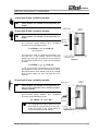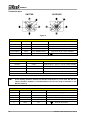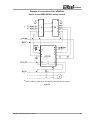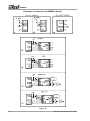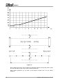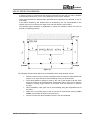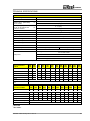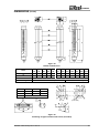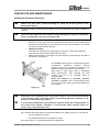
1
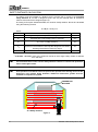
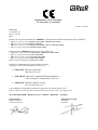
Dichiarazione CE di conformità EC declaration of conformity Torino, 1/1/2010 REER SpA via Carcano 32 10153 – Torino Italy dichiara che le barriere fotoelettriche ADMIRAL sono Dispositivi Elettrosensibili di Sicurezza (ESPE) di : Tipo 4 (secondo la Norma CEI EN 61496-1:2005; CEI EN 61496-2:2007) SIL 3 (secondo la Norma CEI EN 61508:2002) SILCL 3 (secondo la Norma CEI EN 62061:2005 + CEI EN 62061/EC2:2008) PL e (secondo la Norma UNI EN ISO 13849-1:2008) declares that the ADMIRAL photoelectric safety barriers are : Type 4 (according the Standard IEC 61496-1:2004; IEC 61496-2:2006) SIL 3 (according the Standard IEC 61508:1998) SILCL 3 (according the Standard IEC 62061:2005) PL e (according the Standard ISO 13849-1:2006) Electro-sensitive Protective Equipments (ESPE) realizzati in conformità alle seguenti Direttive Europee: complying with the following European Directives: 2006/42/CE "Direttiva Macchine" "Machine Directive" 2004/108/CE "Direttiva Compatibilità Elettromagnetica" "Electromagnetic Compatibility Directive" 2006/95/CE "Direttiva Bassa Tensione" "Low Voltage Directive" e sono identiche all'esemplare esaminato ed approvato con esame di tipo CE da: and are identical to the specimen examined and approved with a CE - type approval by: TÜV SÜD Rail GmbH – Ridlerstrasse 65 – D-80339 – Muenchen – Germany Carlo Pautasso Direttore Tecnico Technical Director Giancarlo Scaravelli Presidente President PHOTOELECTRIC SAFETY BARRIER ADMIRAL INSTALLATION USE AND MAINTENANCE TABLE OF CONTENTS INTRODUCTION ................................................................................................................... 2 OPERATION ......................................................................................................................... 3 INSTALLATION ..................................................................................................................... 4 POSITION ......................................................................................................................................5 SAFETY DISTANCE CALCULATION............................................................................................6 VERTICAL POSITION OF THE BARRIER ....................................................................................6 VERTICAL POSITION OF THE BARRIER ....................................................................................7 HORIZONTAL POSITION OF THE BARRIER ..............................................................................8 ELECTRICAL CONNECTIONS .....................................................................................................9 MULTIPLE SYSTEMS ................................................................................................................ 13 DISTANCE BETWEEN REFLECTING SURFACES .................................................................. 13 USE OF DEFLECTION MIRRORS ............................................................................................. 15 MECHANICAL ASSEMBLY AND OPTIC ALIGNMENT ............................................................. 16 OPERATION AND TECHNICAL DATA................................................................................ 17 SIGNALS..................................................................................................................................... 17 TEST FUNCTION ....................................................................................................................... 18 OUTPUTS STATUS.................................................................................................................... 18 TECHNICAL SPECIFICATIONS................................................................................................. 19 DIMENSIONS (in mm) ......................................................................................................... 21 CHECKOUTS AND MAINTENANCE ................................................................................... 23 TROUBLESHOOTING ................................................................................................................ 24 SPARE PARTS.................................................................................................................... 26 GUARANTEE ...................................................................................................................... 27 8540484 • 28th January 2013 • Rev.10 ADMIRAL This symbol stands by a very important warning concerning the safety of persons. Its non-observance can cause a very serious risk for the exposed personnel. INTRODUCTION The ADMIRAL photoelectric barrier is a multi-beam optoelectronic safety system. It belongs to the family of Type 4 electrosensitive devices for the protection of personnel exposed to risks arising from the use of hazardous machinery or plant. The ADMIRAL barrier, which consists of an Emitter and a Receiver, is a type 4 optoelectronic safety device according to standards EN 61496-1 and prEN 61496-2. The two built-in safe static PNP outputs enable the barrier to be connected to the ADMIRAL SR safety modules or to a safety PLC or to another control system that satisfies the specific requirements and safety level of the application. A diagnostics display on the Emitter and receiver supplies the information that is necessary for the correct use of the device and to evaluate any malfunctions. ADMIRAL is ideal for protecting: Presses, die cutting machines, punching machines, cutting and shearing machines, robotized areas, assembly lines, palletization lines, etc. If necessary, for any safety-related problems contact the competent safety authorities or industrial associations in the country of use. For applications in the food industry, please contact the manufacturer to ensure that the barrier contains materials that are compatible with the chemical agents utilized. The protective function of the optoelectronic devices is not effective in the following cases: 2 If the machine stopping control cannot be actuated electrically and it is not possible to stop all dangerous machine movements immediately and at any time during the operating cycle. If the machine generates dangerous situations due to material being expelled or falling from overhead. 8540484 • 28th January 2013 • Rev.10 ADMIRAL OPERATION If the protected area is clear, the two outputs on the Receiver are active and enable the machine to which they are connected to operate normally. Each time that an object bigger than or equal in size to the resolution of the system intercepts the optical path of one or more beams, the Receiver deactivates the outputs. This condition enables hazardous machine movements to be stopped (by means of an adequate machine emergency stop circuit). The resolution is the minimum dimensions that an object must have so that, on crossing the protected area, it will certainly intercept at least one of the optical beams generated by the barrier (Figure 1). P = Pitch between two lenses D = Diameter of one lens R = Resolution Figure 1 The resolution is constant irrespectively of work conditions, as it only depends on the geometric characteristics of the lenses and the distance between the centres of two adjacent lenses. The height of the protected area is the height that is actually protected by the safety barrier. If the latter is placed horizontally, this value refers to the depth of the protected area. The working range is the maximum operative distance that can exist between the Emitter and the Receiver. ADMIRAL is available with the following resolutions: – 14 mm and 20 mm (protected height from 150 mm to 1800 mm) PROTECTION OF FINGERS – 30 mm (protected height from 150 mm to 1800 mm) PROTECTION OF HANDS – 40 mm (protected height from 300 mm to 1800 mm) PROTECTION OF HANDS – 50 mm and 90 mm (protected height from 300 mm to 1800 mm) PROTECTION OF ARMS AND LEGS ADMIRAL is available also in the Multibeam configuration with the following lens pitch: – 500mm (2 beams), 400mm (3 beams), 300mm (4 beams). PROTECTION OF BODY 8540484 • 28th January 2013 • Rev.10 3 ADMIRAL INSTALLATION Before installing the ADMIRAL safety system, make sure that: The safety system is only used as a stopping device and not as a machine control device. The machine control can be actuated electrically. All dangerous machine movements can be interrupted immediately. In particular, the machine stopping times must be known and, if necessary, measured. The machine does not generate dangerous situations due to materials projecting or falling from overhead; if that is not the case, additional mechanical guards must be installed. The minimum dimensions of the object that must be intercepted are greater than or equal to the resolution of the specific model. Knowledge of the shape and dimensions of the dangerous area enables the width and height of the relative access area to be calculated. Compare these dimensions with the maximum working range and the height of the protected area in relation to the specific model. The general instructions set out below must be taken into consideration before placing the safety device in position. Make sure that the temperature of the environment in which the system is to be installed is compatible with the temperature parameters contained in the technical data sheet. Do not install the Emitter and Receiver close to bright or high-intensity flashing light sources. Certain environmental conditions may photoelectric devices. In order to assure that may be subject to fog, rain, smoke or should be applied to the maximum affect the monitoring capacity of the correct operation of equipment in places dust, the appropriate correction factors Cf working range values. In these cases: Pu = Pm x Cf where Pu and Pm are, respectively, the working and maximum range in meters. 4 8540484 • 28th January 2013 • Rev.10 ADMIRAL The recommended Cf factors are shown in the table below: ENVIRONMENTAL CONDITION CORRECTION FACTOR Cf Fog 0.25 Steam 0.50 Dust 0.50 Dense fumes 0.25 If the device is installed in places that are subject to sudden changes in temperature, the appropriate precautions must be taken in order to prevent the formation of condensation on the lenses, which could have an adverse effect on monitoring. POSITION The position of the ADE Emitter and the ADR Receiver must prevent access to the danger zone from above, below and from the sides, unless at least one of the optical beams has been intercepted. Some useful information regarding the correct position of the barrier is shown in the figure below. Incorrect positioning of barrier Correct positioning of barrier Figure 2 8540484 • 28th January 2013 • Rev.10 5 ADMIRAL SAFETY DISTANCE CALCULATION The barrier must be installed at a distance that is greater than or equal to the minimum safety distance S, so that a dangerous point can only be reached after all hazardous machine movements have stopped (Figure 3). According to European standard EN999, the minimum safety distance S must be calculated using the following formula: S = K (t1 + t2+ t3) + C where: S minimum safety distance mm K approach speed of object to the dangerous area mm/sec t1 response time of the safety barrier in seconds sec t2 response time of the safety interface in seconds (e.g. PLC or safety module*) sec t3 machine response time, in seconds, meaning the time required for the machine to interrupt the dangerous movement following transmission of the stop signal sec c additional distance mm * t2 AD SR1 = 20 msec (refer to the technical manual of each single safety module, if different from AD SR1). The non-observance of the correct safety distance reduces or cancels the protective action of the light curtain. If the position of the barrier does not prevent the operator from having access to the dangerous area without being detected, additional mechanical guards must be installed to complete the system. HAZARDOUS MACHINE S “S”=Safety distance Figure 3 6 8540484 • 28th January 2013 • Rev.10 ADMIRAL VERTICAL POSITION OF THE BARRIER 14 mm and 20 mm resolution models. These models are suitable for the protection of fingers. point of danger safety barrier 30 mm and 40 mm resolution models. These models are suitable for the protection of hands. The minimum safety distance S is calculated according to the following formula: direction of approach S = 2000(t1 + t2 + t3) + 8(D-14) (D=resolution) This formula is valid for distances S between 100 and 500 mm. If this formula results in S being greater than 500 mm, the distance can be reduced to a minimum of 500 mm by means of the following formula: reference plane Figure 4 S = 1600(t1 + t2 + t3) + 8(D-14) If, due to the specific configuration of the machine, the dangerous area can be accessed from above, the highest beam of the barrier must be at a height H of at least 1800 mm from the base G of the machine. 50 mm and 90 mm resolution models. point of danger safety barrier These models are suitable for the protection of arms or legs and must not be used to protect fingers or hands. The minimum safety distance S is calculated according to the following formula: S = 1600(t1 + t2 + t3) + 850 The height H of the highest beam from the base G must never be less than 900 mm, while the height of the lowest beam P must never be more than 300 mm. direction of approach reference plane Figure 5 8540484 • 28th January 2013 • Rev.10 7 ADMIRAL Multibeam Models. point of danger These models are suitable for the protection of the entire body and must not be used to protect arms or legs. safety barrier The minimum safety distance S is calculated according to the following formula: S = 1600 (t1 + t2+ t3) + 850 The reccomended height H from the base (G) must be the following: direction of approach reference plane Figure 6 MODEL BEAMS Reccomended Height H (mm) AD 2B AD 3B AD 4B 2 3 4 400 – 900 300 – 700 – 1100 300 – 600 – 900 - 1200 HORIZONTAL POSITION OF THE BARRIER When the object’s direction of approach is parallel to the floor of the protected area, the barrier must be installed so that the distance between the outer limit of the dangerous area and the most external optical beam is greater than or equal to the minimum safety distance S calculated as follows: point of danger direction of approach S = 1600(t1 + t2 + t3) + 1200 – 0.4H where H is the height of the protected surface from the base of the machine; safety barrier H = 15(D-50) (D=resolution) In this case, H must always be less than 1 meter. reference plane Figure 7 8 8540484 • 28th January 2013 • Rev.10 ADMIRAL ELECTRICAL CONNECTIONS WARNINGS Before making the electrical connections, make sure that the supply voltage complies with that specified in the technical data sheet. Emitter and Receiver units must be supplied with 24Vdc±20% power. The external power supply must comply with the standard EN 60204-1. The external power supply must comply with EN 60204 (it can bridge short-term mains failures of up 20ms). The electrical connections must be made according to the diagrams in this manual. In particular, do not connect other devices to the connectors of the Emitter and Receiver. To guarantee reliability of operation, when using a diode jumper supply unit, its output capacity must be at least 2000µF for each absorbed A. TEST COMMAND AND RANGE SELECTION To select the “Low Range” mode, suggested for all installations below 6m, connect pin 2 to +24Vdc and pin 4 to 0Vdc. In this mode you can give the test command by bringing pin 2 to 0Vdc too. To select the “High Range” mode, for all installations above 6m, connect pin 2 to 0Vdc and pin 4 to +24Vdc. In this mode you can give the test command by bringing pin 4 to 0Vdc too. Please see table 2. 8540484 • 28th January 2013 • Rev.10 9 ADMIRAL Connector pins EMITTER RECEIVER Figure 8 EMITTER NUMBER COLOR NAME MEANING 1 Brown 24 VDC Power supply (positive) 2 (see table 2) White SEL RANGE/TEST1 Input 1 for range / TEST selection 3 Blue 0 VDC Power supply (negative) 4 (see table 2) Black SEL RANGE/TEST2 Input 2 for range / TEST selection 5 Grey PE Ground connection Table 1 RANGE and TEST SELECTION PIN 2 PIN 4 MEANING +24 Vdc 0 Vdc * LOW range (0 6m) (0 2m for 14mm models) 0 Vdc * +24 Vdc HIGH range (1 18m) (0 5m for 14mm models) 0 Vdc * 0 Vdc * EMITTER IN TEST CONDITION +24 Vdc +24 Vdc Condition not allowed * (0 Vdc or open circuit) Table 2 If the working distance between the Emitter and Receiver is less than 6m (2m for 14mm resolution models), is recommended to use the low range (selectable on the Emitter) (table 2). RECEIVER NUMBER COLOR NAME MEANING 1 Brown 24 VDC Power supply (positive) 2 White OSSD1 Static output No. 1 (PNP active high) 3 Blue 0 VDC Power supply (negative) 4 Black OSSD2 Static output No. 2 (PNP active high) 5 Grey PE Ground connection Table 3 10 8540484 • 28th January 2013 • Rev.10 ADMIRAL Example of connection of the ADMIRAL barrier to the REER AD SR1 safety module * + + * Refer to table 2, page 10 for the correct connection of pins 2 and 4 Figure 9 8540484 • 28th January 2013 • Rev.10 11 ADMIRAL Examples of connection of ADMIRAL barrier Figure 10 12 8540484 • 28th January 2013 • Rev.10 ADMIRAL Warnings regarding the connection cables 2 For connections over 50 m long, use cables with a cross-section area of 1 mm . The power supply to the barrier should be kept separate from that to other electric power equipment (electric motors, inverters, frequency converters) or other sources of disturbance. Connect the Emitter and the Receiver to the ground outlet. The connection cables must follow a different route to that of the other power cables. MULTIPLE SYSTEMS When more than one ADMIRAL system is used, precautions must be taken to avoid optical interference between them: install units so that the beam emitted by the Emitter of one system can only be received by the relative Receiver. Figure 11 illustrates some examples of correct positioning when two photoelectric systems are installed. Incorrect positioning could generate interference, and may result in malfunctioning. Systems installed alongside each other: A Installation of two adjacent Emitters Overlapping systems: B L-shaped installation: C Crossed positioning of Emitters and receivers Figure 11 DISTANCE BETWEEN REFLECTING SURFACES The presence of reflecting surfaces in proximity of the photoelectric barrier may generate spurious reflections that prevent monitoring. With reference to Figure 12, object A is not detected because surface S reflects the beam and closes the optical path between the Emitter and Receiver. A minimum distance d must therefore be maintained between any reflecting surfaces and the protected area. The minimum distance d must be calculated according to the distance l between the Emitter and the Receiver, considering that the angle of projection and reception is 4°. Figure 12 Figure 13 illustrates the values for the minimum distance d that must be maintained when the distance l between the Emitter and Receiver is changed. 8540484 • 28th January 2013 • Rev.10 13 ADMIRAL Figure 13 After installing the system, check whether any reflecting surfaces intercept the beams, first in the centre and then in the vicinity of the Emitter and Receiver. During these operations, the red LED on the Receiver should never, for any reason, switch off. 14 8540484 • 28th January 2013 • Rev.10 ADMIRAL USE OF DEFLECTION MIRRORS In order to protect or control areas that can be accessed from more than one side, in addition to the Emitter and Receiver, one or more deflection mirrors can be installed. These mirrors enable the optical beams generated by the Emitter to be deviated on one or more sides. If the beams emitted by the Emitter must be deviated by 90°, the perpendicular to the surface of the mirror must form an angle of 45° with the direction of the beams. The following figure illustrates an application in which two deviation mirrors are used to provide a U-shaped protection. Figure 14 The following rules should be taken into consideration when using deviation mirrors: Place the mirrors so as to ensure compliance with the minimum safety distance S (Figure 14) on each side from which the danger zone can be accessed. The working distance (range) is given by the sum of the lengths of all the sides that give access to the protected area. (Remember that for each mirror used the maximum working range between the Emitter and the Receiver is reduced by 15%). During installation, take great care to avoid twisting along the longitudinal axis of the mirror. Make sure, by standing near to and on the axis of the Receiver, that the entire outline of the Emitter is visible on the first mirror. The use of more than three deviation mirrors is not recommended. 8540484 • 28th January 2013 • Rev.10 15 ADMIRAL MECHANICAL ASSEMBLY AND OPTIC ALIGNMENT The Emitter and the Receiver must be assembled opposite each other (at a distance specified in the technical data sheet). Use the fastening brackets and inserts supplied with the system to place the Emitter and the Receiver so that these are aligned and parallel to each other and with the connectors facing the same way. Depending on the dimensions and the shape of the support on which they are to be installed, the Emitter and Receiver must be assembled with the fastening inserts at the back, or else by fitting these in the side groove (Figure 15). Perfect alignment of the Emitter and Receiver is essential in order to assure correct barrier operation. The indicator LEDs on the Emitter and Receiver facilitate this operation. Figure 15 Position the optical axis of the first and last beam of the Emitter on the same axis as that of the corresponding beams on the Receiver. Move the Emitter in order to find the area within which the green LED on the Receiver stays on, then position the first beam of the Emitter (the one close to the indicator LEDs) in the centre of this area. Using this beam as a pivot, effect small sideways movements of the opposite end to move to the protected area clear condition. The green LED on the Receiver will indicate this condition. Lock the Emitter and Receiver in place. During these operations it may be useful to check the yellow weak signal LED on the Receiver. Upon completion of alignment, this LED must be off. If the Emitter and the Receiver are assembled in areas that are subject to strong vibrations, the use of vibration-damping supports is recommended, in order to prevent circuit malfunctions. 16 8540484 • 28th January 2013 • Rev.10 ADMIRAL OPERATION AND TECHNICAL DATA Receiver Emitter SIGNALS * LED COLOUR STATUS DISPLAY (4) CONDITION 1 Yellow On 2 Red On 8 System activated. Initial TEST. 1 Yellow On 3 Green On L/H TEST condition 3 Green On L Normal operation, low range 3 Green On H Normal operation, high range 2 Red On FAULT CODE Malfunction * LED 5 6 6 5 7 6 COLOUR Yellow Red Red Yellow Green Red STATUS On On On On On On DISPLAY (8) CONDITION 8 System activated. Off Off Off FAULT CODE Protected area engaged Weak signal received Protected area clear Malfunction * N.B.: For the meaning of the number that is displayed in case of a malfunction, please refer to the “TROUBLESHOOTING” paragraph in this manual. Figure 16 On the emitter of the multibeam models, near each beam, is present a red led which permits an easy detection of the beam. 8540484 • 28th January 2013 • Rev.10 17 ADMIRAL TEST FUNCTION The Admiral light curtain does not dispose of a start/restart interlock circuit. In most applications this safety function is necessary. The safety relay Admiral ADSR1 permits to implement this function in a safe way according to IEC 61496-1. Please consider the risk-analysis of your application about this matter. By means of the test function, which simulates occupation of the protected area, it possible to verify the operation of the entire system by means of an external supervisor (e.g. PLC, control module, etc.). The ADMIRAL barrier system features an automatic self-diagnosis function that enables it to detect response time malfunctions (this time is declared for each model). This safety system is permanently active and does not require any interventions from the outside. The TEST function is available should the user wish to check equipment connected downstream of the barrier (without physically entering the protected area). By means of this function the OSSDs can be switched from ON to OFF as long as the function remains active. Please see table 2 (page 10) for details about the use of the test function. The minimum duration of the TEST function must be 80 msec. OUTPUTS STATUS The ADMIRAL features two static PNP outputs on the Receiver, the status of which depends on the condition of the protected area. The maximum load allowed is 500mA at 24VDC, which corresponds to a resistive load of 48. Maxim load capacity corresponds to 2.2F. The meaning of the status of outputs is defined in the table below. Any short circuit between outputs or between outputs and 24VDC or 0VDC power supplies is detected by the barrier. NAME OF SIGNAL OSSD1 OSSD2 OSSD1 OSSD2 CONDITION MEANING 24VDC Barrier clear condition 0VDC Barrier engaged condition or failure detected Table 4 In the protected area clear condition, the Receiver supplies a voltage of 24 VDC on both outputs. The required load must therefore be connected between the output terminals and the 0DVC (Figure 17). Figure 17 18 8540484 • 28th January 2013 • Rev.10 ADMIRAL TECHNICAL SPECIFICATIONS TECHNICAL SPECIFICATIONS OF ADMIRAL BARRIERS Protected height mm 160 – 1810 Resolutions mm 14 – 20 – 30 – 40 – 50 – 90 Working range (selectable) 14mm models 0 2 (low) m Working range (selectable) 20, 30, 40, 50, 90mm and Multibeam models Safety outputs 0 5 (high) 0 6 (low) m 1 18 (high) 2 PNP – 500mA @24VDC Response time ms 3 27 (see tables for specific models) Power supply Vdc 24 20% Connections Connectors M12 5-pole Max. conn. length m 100 Operating temp. °C 0 55 °C mm 35 x 45 Protection rating * IP 65 Dimensions of section Max. consumption W 2 (Emitter) 3 (Receiver) Light curtain lifetime 20 years IEC 61496-1:2004 IEC 61496-2:2006 IEC 61508:1998 Type 4 SIL 3 Safety level SILCL 3 IEC 62061:2005 PL e - Category 4 ISO 13849-1:2006 *) Devices are not suitable for outdoor use without supplementary measures 14 mm resolution models AD 151 AD 301 AD 451 AD 601 AD 751 AD 901 AD AD 1051 1201 AD 1351 AD 1501 AD 1651 AD 1801 Number of beams 15 30 45 60 75 90 105 120 135 150 165 180 Response time 6 7,5 9,5 11,5 13,5 15,5 17 19 21 23 25 27 Overall barrier ht. mm 261 411 561 711 861 1011 1161 1311 1461 1611 1761 1911 PFHd * 1,02E-8 1,17E-8 1,33E-8 1,48E-8 1,63E-8 1,79E-8 1,94E-8 2,10E-8 2,25E-8 2,40E-8 2,56E-8 2,71E-8 DCavg # 97,77% 98,07% 98,25% 98,38% 98,47% 98,53% 98,58% 98,63% 98,66% 98,69% 98,71% 98,73% 92,14 81,96 73,80 67,12 61,55 56,83 52,79 MTTFd # 100 years CCF # 80% 20 mm resolution models AD 152 AD 302 AD 452 AD 602 AD 752 AD 902 AD AD AD AD AD AD 1052 1202 1352 1502 1652 1802 Number of beams 15 30 45 60 75 90 105 120 135 150 165 180 Response time 6 7.5 9.5 11.5 13.5 15.5 17 19 21 23 25 27 261 411 561 711 861 1011 1161 1311 1461 1611 1761 1911 PFHd * 1,02E-8 1,17E-8 1,33E-8 1,48E-8 1,63E-8 1,79E-8 1,94E-8 2,10E-8 2,25E-8 2,40E-8 2,56E-8 2,71E-8 DCavg # 97,77% 98,07% 98,25% 98,38% 98,47% 98,53% 98,58% 98,63% 98,66% 98,69% 98,71% 98,73% 92,14 81,96 73,80 67,12 61,55 56,83 52,79 Overall barrier ht. MTTFd # mm years CCF # 100 80% * IEC 61508 # ISO 13849-1 8540484 • 28th January 2013 • Rev.10 19 ADMIRAL 30 mm resolution models AD 153 AD 303 AD 453 AD 603 AD 753 AD 903 Number of beams Response time Overall barrier ht. mm PFHd * 8 6 261 16 6 411 24 7 561 32 8 711 40 9 861 48 56 64 72 80 88 96 10 11 12 13 14 15 16 1011 1161 1311 1461 1611 1761 1911 9,58E-9 1,05E-8 1,14E-8 1,24E-8 1,33E-8 1,42E-8 1,51E-8 1,61E-8 1,70E-8 1,79E-8 1,88E-8 1,98E-8 97,58% 97,84% 98,02% 98,16% 98,26% 98,34% 98,40% 98,45% 98,50% 98,53% 98,57% 98,59% 99,34 91,93 85,55 79,99 DCavg # MTTFd # CCF # 80% AD 304 10 6 411 AD 454 15 6 561 AD 604 20 6 711 AD 754 25 7 861 AD 904 30 8 1011 AD 1054 35 8 1161 AD 1204 40 9 1311 AD 1354 45 9,5 1461 AD 1504 50 10 1611 AD 1654 55 11 1761 AD 1804 60 11 1911 1,01E-8 1,09E-8 1,17E-8 1,24E-8 1,32E-8 1,39E-8 1,47E-8 1,54E-8 1,62E-8 1,69E-8 1,77E-8 97,76% 97,93% 98,06% 98,16% 98,24% 98,31% 98,37% 98,42% 98,46% 98,49% 98,52% 93,89 100 years 80% 50 mm resolution models Number of beams Response time Overall barrier ht. mm PFHd * DCavg # MTTFd # CCF # 100 years 40 mm resolution models Number of beams Response time Overall barrier ht. mm PFHd * DCavg # MTTFd # CCF # AD AD AD AD AD AD 1053 1203 1353 1503 1653 1803 AD 305 8 6 411 AD 455 12 6 561 AD 605 16 6 711 AD 755 20 6 861 AD 905 24 7 1011 AD 1055 28 7 1161 AD 1205 32 8 1311 AD 1355 36 8,5 1461 AD 1505 40 9 1611 AD 1655 44 9,5 1761 AD 1805 48 10 1911 1,00E-8 1,07E-8 1,14E-8 1,21E-8 1,28E-8 1,35E-8 1,42E-8 1,49E-8 1,56E-8 1,63E-8 1,70E-8 97,72% 97,89% 98,02% 98,12% 98,21% 98,28% 98,33% 98,38% 98,43% 98,46% 98,49% 99,66 100 years 80% 90 mm resolution models AD 309 AD 459 AD 609 AD 759 AD 909 AD 1059 AD 1209 AD 1359 AD 1509 AD 1659 AD 1809 Number of beams Response time Overall barrier ht. mm PFHd * 5 6 411 7 6 561 9 6 711 11 6 861 13 6 1011 15 6 1161 17 6 1311 19 6 1461 21 6,5 1611 23 7 1761 25 7 1911 9,78E-9 1,04E-8 1,09E-8 1,15E-8 1,21E-8 1,27E-8 1,32E-8 1,38E-8 1,44E-8 1,50E-8 1,55E-8 97,65% 97,81% 97,93% 98,04% 98,12% 98,19% 98,25% 98,30% 98,35% 98,39% 98,42% DCavg # MTTFd # 100 80% years CCF # Multibeam Models Number of beams Distance between beams Response time Overall barrier ht. PFHd * DCavg # MTTFd # CCF # years mm ms mm AD 2B 2 500 6 711 AD 3B 3 400 6 1011 AD 4B 4 300 6 1111 8,97E-9 9,15E-9 9,32E-9 97,30% 97,40% 97,49% 100 80% * IEC 61508 # ISO 13849-1 20 8540484 • 28th January 2013 • Rev.10 ADMIRAL DIMENSIONS (in mm) Figure 18 Emitter and Receiver Model A B (PROTECTED AREA) C AD 150 AD 300 AD 450 AD 600 AD 750 AD 900 AD 1050 AD 1200 AD 1350 AD 1500 AD 1650 AD 1800 251 401 551 701 851 1001 1151 1301 1451 1601 1751 1901 160 310 460 610 760 910 1060 1210 1360 1510 1660 1810 85 Mounting 2 LS Brackets with 2 mounting inserts Model AD 2B AD 3B AD 4B A 701 1001 1101 B 610 910 1010 C 3 LS Brackets with 3 mounting inserts 135 R3.25 (on all slots) Figure 19 Fastening LS type brackets and inserts (included) 8540484 • 28th January 2013 • Rev.10 21 ADMIRAL Figure 20 LL and LH TYPE fastening brackets (optional) Inserts M8 Model H SP100S 250 SP300S 400 SP400S 540 SP600S 715 SP700S 885 SP900S 1060 SP1100S 1230 SP1200S 1400 SP1300S 1450 SP1500S 1600 SP1600S 1750 SP1800S 1900 Figure 21 Fastening brackets for deviation mirrors Figure 22 Deviation mirrors 22 8540484 • 28th January 2013 • Rev.10 ADMIRAL CHECKOUTS AND MAINTENANCE Verification of barrier efficiency. Before each work shift or before switching on, check the correct operation of the photoelectric barrier. Proceed as follows, intercepting the beams using the appropriate test object (available on request). The correct test object must be used for testing, depending on the barrier resolution. Please see page 25 for the correct ordering code. Refer to Figure 23: Introduce the test object into the protected area and move it slowly, starting from the top and moving down (or vice versa), first in the centre and then in the vicinity of both the Emitter and the Receiver. Multibeam models: Intercept each beam with an opaque object, first in the center of the detection zone and then close to the emitter and the receiver. Make sure that during each stage of the test object’s movements the red LED on the Receiver is always on. The ADMIRAL barrier does not require any specific maintenance operations; however, periodic cleaning of the front protective surfaces of the Emitter and Receiver optics is recommended. Wipe using a clean, damp cloth; in particularly dusty environments, after cleaning the front surface, the use of an anti-static spray is recommended. Never use abrasive or corrosive products, solvents or alcohol, which could damage parts. Do not use woollen cloths, that could electrify the front surface. Figure 23 Grooving or fine scratching of the front plastic surfaces can increase the amplitude of the emission angle of the light curtain, jeopardising detection efficiency in the presence of lateral reflecting surfaces. It is therefore fundamental to pay particular attention during the cleaning phases of the curtain front window, especially in environments where abrasive dusts are present. (E.g. cement factories, etc). If the yellow weak signal LED on the Receiver switches on (LED 5 in Figure 16), check that: – the front surfaces are clean; – the Emitter and Receiver are aligned correctly. If the LED stays on, contact the REER service department. 8540484 • 28th January 2013 • Rev.10 23 ADMIRAL TROUBLESHOOTING The instructions shown on the display of the Emitter and the Receiver enable the user to identify the cause of a number of system malfunctions. As described in the “SIGNALS” paragraph of this manual, in case of a failure, the system is set to the stop condition and the display of each unit shows the letter F followed by a numerical code that identifies the type of failure. (See table below). EMITTER CODE DISPLAYED DIAGNOSIS Anomalous connection of SEL RANGE/TEST signals REMEDY Check the connection of terminals 2 and 4 (SEL RANGE/TEST) on the connector carefully. Internal failure relating to the add-on boards Internal failure relating to the microcontroller boards Return the equipment to ReeR laboratories for repair. Internal failure RECEIVER CODE DISPLAYED DIAGNOSIS Overcurrent on one or both outputs (OSSD) REMEDY Check the connection of terminals 2 and 4 (OSSD) on the connector carefully. If necessary, reduce the load by reducing the requested current to max. 500mA (2.2 F). Locate the Emitter that is the cause of the disturbance and proceed as follows: Detection of a hazardous interfering Emitter condition. The reduce the range of the interfering Emitter from High to Low (see table 2) Receiver is able to receive the beams emitted by two different Invert the positions of the Emitter and Receiver Emitters at the same time. Move the interfering Emitter to prevent this from illuminating the (This fault is displayed for at Receiver least 30 seconds). Use opaque guards to shield the beams coming from the interfering Emitter 24 Connection of load between static outputs (OSSD) and the positive power supply line (+ 24 Vdc) Check the connection of terminals 2 and 4 (OSSD) on the connector carefully. Caution: the load must be positioned between the outputs (OSSD) and 0 Vdc. Internal failure relating to the microcontroller boards Return the equipment to ReeR laboratories for repair. Erroneous connection of static outputs (OSSD). Check the connection of terminals 2 and 4 (OSSD) on the connector carefully. These terminals can be connected directly to + 24 Vdc or to 0 Vdc. 8540484 • 28th January 2013 • Rev.10 ADMIRAL Probable short circuit between the two outputs (OSSD) Check the connection of terminals 2 and 4 carefully. In any case, when faced with a system stoppage, switch the system off and then on again, to exclude any occasional electromagnetic disturbances. Should the problem persist after carrying out the checks described above, contact REER’s service department. In case of continued malfunctioning: verify the integrity of electrical connections and check that these have been made correctly; check that the supply voltage levels comply with those specified in the technical data sheet; the barrier power supply should be kept separate from that of the other electric power equipment (electric motors, inverters, frequency converters) or other sources of disturbance. make sure that the Emitter and the Receiver are correctly aligned and that the front surfaces are perfectly clean. If it is not possible to clearly identify the malfunction and to remedy it, stop the machine and contact Reer's Assistance Service. If correct system operation cannot be restored after carrying out the above procedures, send the equipment to REER’s laboratories, complete with all parts, stating clearly: the product code number (the P/N field is shown on the product label) serial number (the S/N field is shown on the product label) date of purchase; period of operation; type of application; fault. 8540484 • 28th January 2013 • Rev.10 25 ADMIRAL SPARE PARTS MODEL 26 ARTICLE CODE AD SR1 ADMIRAL AD SR1 Safety Relay 1330900 AD SR2 ADMIRAL AD SR2 Safety Relay 1330901 CD5 Straight 5-pin M12 female connector, 5 m cable 1330950 CD95 90° 5-pin M12 female connector, 5 m cable 1330951 CD15 Straight 5-pin M12 female connector, 15 m cable 1330952 CD915 90° 5-pin M12 female connector, 15 m cable 1330953 CDM9 Straight 5-pin M12 female connector PG9 1330954 CDM99 90° 5-pin M12 female connector PG9 1330955 TR14 14mm diameter test rod 1330960 TR20 20mm diameter test rod 1330961 TR30 30mm diameter test rod 1330962 TR40 40mm diameter test rod 1330963 TR50 50mm diameter test rod 1330964 FB 4 Set of 4 fastening brackets 1330970 FB 6 Set of 6 fastening brackets 1330971 LL Set of 4 fastening brackets LL type 7200037 LH Set of 4 fastening brackets LH type 7200081 FI 4 Set of 4 fastening inserts 1330972 FI 6 Set of 6 fastening inserts 1330973 SFB Set of 4 swivel fastening brackets 1330974 SAV-1 Set of 4 anti-vibration supports for LL/LS type brackets 1200084 SAV-2 Set of 6 anti-vibration supports for LH/LS type brackets 1200085 8540484 • 28th January 2013 • Rev.10 ADMIRAL GUARANTEE All new ADMIRAL systems are guaranteed by REER for a period of 12 (twelve) months under normal working conditions, against defects due to faulty materials and workmanship. During the aforesaid period, REER promises to replace faulty parts free of charge. This guarantee covers both material and labour. REER reserves the right to decide whether to repair equipment or replace it with equipment of the same type or having the same characteristics. The validity of this guarantee is subject to the following conditions: The user must notify REER of the fault within twelve months following the date of delivery of the product. The equipment and all parts thereof must be in the condition in which they were supplied by REER. The defect or malfunction must not arise directly or indirectly from: – – – – Improper use Non-observance of the instructions for use; Negligence, inexperience, improper maintenance; Repairs, modifications and adjustments carried out by personnel not authorised by REER, tampering, etc.; – Accidents or collisions (also during transportation or due to acts of God); – Other reasons for which REER cannot be held responsible. Repairs will be carried out at REER’s laboratories, to which the material must be consigned or forwarded: transport costs and any damage or loss of material during transportation will be charged to the Customer. All replaced products and parts are property of REER. REER does not recognise any other form of guarantee or rights other than those expressly stated above; no requests for compensation for damages incurred for costs, suspension of activities or any other events or circumstances related in any way to malfunctioning of the product or any parts thereof will be taken into consideration. In order to ensure the correct operation of the photoelectric barrier, careful and full compliance with all the rules, instructions and warnings stated in this manual is essential. REER s.p.a. declines all responsibility for events arising from non-compliance with all or part of the aforesaid instructions. Specifications subject to change without warning. No part of this manual may be reproduced without the prior consent of REER. 8540484 • 28th January 2013 • Rev.10 27