1
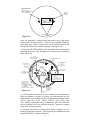
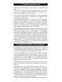
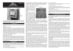
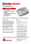
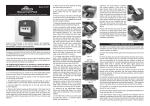
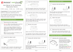
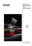
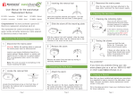
Model: Ei 428
RADIOLINK RELAY
FOR USE WITH EI168, 405, 405TY & 3105RF
Instruction Manual
MODEL Ei428
Contains vital information on the products operation and
installation. Read and retain carefully. If you are just installing
this product the manual MUST be given to the householder.
1. Introduction
The Ei428 RadioLINK Relay Module is a device that switches
a relay upon receipt of an alarm signal from a suitable Ei
smoke/heat alarm. The electrically isolated contacts can be
used for many applications such as signalling, turning on
lights, etc. The Ei428 is designed to operate with Ei
RadioLINK products (Ei168, 405, 405TY, 407, 410, 411 &
3105RF).
The Ei428 RadioLINK Relay Module is powered by the
230VAC mains and has rechargeable back-up cells. As supplied the relay operates continuously (i.e. it switches when
one of the smoke / heat alarms detects fire and switches back
when the smoke clears). When the slide switch is moved to
the pulse ‘P’ position (see figure 1b) the relay will switch when
fire is detected but will automatically switch back after 5 seconds. This is commonly used with warden call systems where
only momentary short circuit signalling is required.
2. Installation
WARNING: Mains powered Ei428 RadioLINK Relay modules
should be installed by a qualified electrician in accordance
with the Regulations for Electrical Installations published by
the Institution of Electrical Engineers (UK) (i.e. BS7671)
Failure to install the unit correctly may expose the user to
shock or fire hazards. This unit is not waterproof and must not
be exposed to dripping or splashing.
1. Choose a suitable mounting position near the mains supply
and the device to be connected to the relay. Keep it away
from metal surfaces or large metal objects (e.g. water cylinder, fuse boards) which can reduce the RF signal range.
2. Disconnect the AC mains supply from the circuit that is
going to be used.
3. Where the incoming wiring is on the surface of the ceiling,
the appropriately sized trunking / conduit must be chosen to
mate with the unit. Use a sharp knife to remove the material
1
INDICATOR LIGHT
GREEN - MAINS
RED - HOUSE CODING
OR LOW BATTERY
HOUSE
CODE
SWITCH
MODEL: Ei428
RADIOLINK
RELAY
WARNING: DISCONNECT
MAINS BEFORE REMOVAL
COVER ATTACHMENT
SCREWS
Figure 1a
from the knockout, making sure that there is no gap when
mated with ducting/conduit. There is one suitable knockout
(the other two surface entries are not recommended as the
wiring will reduce the antenna signal). See figure 1b.
4. Screw the Ei428 module to the wall after first removing the
required knockout and bringing the house wires through it
(see figure 1b).
P - PULSE
RELAY CHANGES
FOR 5 SECONDS
C - CONTINUOUS RELAY
INDICATOR
LIGHT
ANTENNA
(KEEP CABLES
AWAY)
C
P
REAR ENTRY
KNOCKOUT
ON
SCREW
MOUNTING
HOLES
OFF
RECHARGEABLE
CELLS
ON/OFF
SLIDE SWITCH
HOUSE CODE
SWITCH
NO NC C
N
IC
L
L
IC
N
CONNECT MAINS
TO TERMINAL BLOCK
L - LIVE
N - NEUTRAL
(IC - INTERCONNECT
NOT NORMALLY USED)
CONNECT RELAY
WIRES TO THE
TERMINAL BLOCK
NO - NORMALLY OPEN
NC - NORMALLY CLOSED
C - COMMON
(DOUBLE INSULATE ALL WIRES)
SURFACE
CONDUIT
CABLE
ENTRY
Figure 1b
5. Connect the house wires (L-Live, N-Neutral) to the terminal
block as shown in figure 1b (Note the interconnect can be
hard wired to a non radio link Ei mains powered smoke alarm
(Ei141, 144, 146, 151TL, 154TL, 156TLH, 161, 161R, 164,
166, 166R) to switch the relay, if required). NB: The unit must
not be earthed so do not connect a green / yellow or copper
earth wire to any terminal.
6. Connect the wires to the required relay contacts for controlling the auxiliary device. (The contacts are isolated and are
rated at 250VAC, 5 amps resistive).
2
If momentary relay operation is required, carefully and gently
slide the yellow switch to the “P” position with a small screwdriver (see figure 1b). This must be done before the mains
power is connected or the rechargeable cells are activated.
7. Connect the rechargeable cells by carefully and gently sliding the switch to the “on” position See figure 1b.
8. Fit and screw the cover to the module pillars using the two
screws supplied.
9. Connect the mains power to the Ei428 module. Check the
green light is on. If a red light flashes every 10 seconds then
switch off the mains power, remove the cover and check that
the battery slide switch is in the “On” position (see figure 1b).
Replace the cover and turn the mains power back on. If there
is still a problem the rechargeable cells may be depleted,
leave the unit on mains power for 2 hours to charge and test
again.
10. Press and hold the House Code switch through the hole
in the cover using a small screwdriver, see figure 1a, until the
green light changes to red. Release the switch and the light
will flash red quickly, a few times. The red light will then flash
every 5 seconds (this is a dual colour light so the green light
remains on when the red light is off and vice versa). Similarly,
put all the other RadioLINK units in the property into House
Code Mode (see relevant user instructions) within 15 minutes
(before the timeout period expires).
11. Check that all the RadioLINK units have communicated
with each other by counting the number of times the light
flashes on each unit in turn (the light will flash red on the
Ei428 relay modules, amber on the Ei168 bases and blue on
the Ei405/405TY). For example, 3 units in the system should
have 3 flashes every 5 seconds, 4 units should have 4 flashes and so on (if there is a problem see section 3).
12. All the units will automatically exit the house code mode
after 15 minutes. We recommend that you manually exit the
house code mode by pressing and holding the house code
switch, on all units, until the red/amber/blue light (depending
on the unit) turns on. This reduces the risk of accidentally
house coding your alarms and other components with nearby
systems.
13. Check the RadioLINK communication by pressing the
test/hush button for up to 60 seconds on each alarm. Ensure
that the device connected to the relay contacts operates.
After 60 seconds release the test button – check the device
switches off. (If the continuous/pulse slide switch is in the
pulse position, check the relay just switches on for 5 seconds
and then switches off).
If an Ei410 is being used, (with the relay in continuous ‘C’ on
mode), check that pressing the test button causes the relay to
switch and that releasing the test button causes the relay to
switch back.
3
3. Troubleshooting RF Link
If, when checking the radio link interconnection, some of the
Ei428 RadioLINK Relays do not respond to the button test,
then:
(i) Ensure you have held the smoke/heat alarm test button
down until the light has come on twice, for 3.5 seconds each
time (this could take up to 20 seconds).
(ii) Convert one of the RadioLink units (an Ei168 or Ei405) that
is centrally located within the house in to a “Repeater” (see
relevant user instructions).
(iii) Re-locate/rotate the units. There are a number of reasons
why the radio link signals may not reach all the RadioLink
Relays in your system (see section on “Limitations of Radio
Frequency Signals”). Try rotating the unit or re-locating the
units (e.g. move them away from metal surfaces or wiring) as
this can significantly improve signal reception.
Rotating and/or relocating the units may move them out of the
range of existing units even though they may have already
been house coded correctly in the system. It is important
therefore to check that all detectors/relays are communicating
in their final installed positions. If units are rotated and/or
resited, we recommend that all units are returned to the factory settings (press and hold the house code switch on for
about 6 seconds until the relevant light comes on and then
flashes slowly). Then house code all units again in their final
positions as indicated above. The radio link interconnection
should then be re-checked again.
4. Limitations of Radio Communications
Ei Electronics radio communication systems are very reliable
and are tested to high standards. However, due to their low
transmitting power and limited range (required by regulatory
bodies) there are some limitations to be considered.
(i) Radio equipment, such as the Ei428 RadioLink Relay,
should be tested regularly at least weekly. This is to determine whether there are sources of interference preventing
communication. The radio paths may be disrupted by moving
furniture or renovations, and so regular testing protects
against these and other faults.
(ii) Receivers may be blocked by radio signals occurring on or
near their operating frequencies, regardless of the house
coding.
The Ei428 Relay has been tested to EN 300 220-1 V1.3.1
(2000-09) in accordance with the requirements of En 300
220V1.1.1 (2000-09). These tests are designed to provide
reasonable protection against harmful interference in residential installations. This equipment generates, uses and can
radiate radio frequency energy and, if not installed and used
in accordance with the instructions, may cause harmful interference to radio and television reception.
However, there is no guarantee that interference will not occur
4
in a particular installation. If this device does cause such
interference, which can be verified by turning the device on
and off (remove the mains supply and turn off back up power
supply), the user is encouraged to eliminate the interference
by one or more of the following measure:
(i) Re-orientate or re-locate the unit
(ii) Increase the distance between the Ei428 and the device
being affected.
(iii) Connect the device being affected to a mains outlet on a
circuit different from the one that supplies the Ei428.
(iv) Consult the supplier or an experienced radio/television
technician.
5. Checking & Maintaining Your Smoke Alarm System
We recommend a weekly check is made of your alarm system. When checking the system also check the Ei428 as follows:
(i) Check that the green mains power indicator is on (if this is
off, check circuit breaker fuse, wiring etc.).
(ii) Check the relay switches and that the associated device
operate when the system is in alarm (e.g. due to a smoke
alarm test button being pressed).
6. Checking RadioLINK Relay Back-Up Cells
It is important to check that the rechargeable cells in the Ei428
Relay module are switched on, charged and capable of powering the system.
(i) Check that the green light is on and that it is not flashing
red once every 10 seconds. If it is, this indicates that either
the rechargeable cells in the RadioLink Relay are not connected or depleted. Disconnect the mains supply. Remove
the cover and gently slide the battery slide switch (see fig 1b)
into the “on” position. If the green light is still changing to
flashing red every 10 seconds, leave it for 2 hours to charge
and then re-check it.
(ii) Disconnect the mains supply. The green light in the Ei428
will turn off. Check the radio link relay as described in section
2, item 13 above. Check the red light does not flash every 10
seconds.
(iii) If everything is satisfactory, re-connect the mains.
If the relay fails to operate or the red light continues to flash
every 10 seconds (even after (i) above) then the unit is defective and must be replaced (see getting your RadioLink Relay
serviced as per section 7 below).
End of Life
After 10 years (see date on the side of the RadioLink Relay
Base) the Ei428 Relay module must be replaced.
5
7. Getting your RadioLink Base Serviced
If your RadioLink Relay fails to work after your have carefully
read all the instructions, checked that the unit has been
installed correctly, and is receiving AC power (green light on)
contact Customer Assistance at the nearest address given at
the end of this leaflet. If it needs to be returned for repair or
replacement, open cover and turn off rechargeable cells with
slide switch (see fig 1b). Put the RadioLink Relay in a padded
box and send it to “Customer Assistance and Information” at
the nearest address given on the unit or in this leaflet. State
the nature of the fault, where the RadioLink Base was purchased and date of purchase.
8. Five Year Guarantee
Ei Electronics, guarantees this Ei 428 RadioLink Relay for five
years from date of purchase against any defects that are due
to faulty materials or workmanship. This guarantee only
applies to normal conditions of use and service, and does not
include damage resulting from accident, neglect, mis-use,
unauthorised dismantling, or contamination howsoever
caused. This guarantee does not cover costs associated with
the removal and/or installation of units. If this RadioLink
Relay should become defective within the guarantee period, it
must be returned to Ei Electronics, with proof of purchase,
carefully packaged, and with the problem clearly stated. (see
“Getting Your RadioLink Relay Serviced”). We shall at our
discretion repair or replace the faulty unit.
Do not interfere with the RadioLink Relay or attempt to tamper with it. This will invalidate the guarantee, but more importantly may expose the user to shock or fire hazards. This
guarantee is in addition to your statutory rights as a consumer.
9. Technical Specification
Mains: 230 VAC, 40mA, 50HZ, 0.8W
Mains Indicator: Green LED lights continuously (apart from
when it switches momentarily to red as outlined below)
Battery Back-Up: Rechargeable Built-In Lithium Cells
(operates for up to 2 months in standby)
Approvals: Complies with EMC, Electrical Safety and Radio
Regulations – including requirements of the RTTE Directive
Compatibility 1999/5/EC (RF Performance to EN300220-3,
EMC to EMC 301489-3) – independently tested
Humidity Range: 15% to 95% RH (non-condensing)
Radio Frequency: 868.499 MHz (Regulated 1% duty cycle band)
RF Power: +5dBm
Range: 150 meters (minimum) in free space
RF RECEPTION
Alarm Signal Reception: Switches latching relay for 60 seconds (with switch in continuous mode) unless it receives an
6
alarm cancel signal within that period. It switches the relay for
5 seconds with the switch in pulse mode.
Low Battery Indication: Red light flashes every 10 seconds.
(The green light switches off when the red is on).
Size of System: : the recommended maximum number of
Radiolink units should not exceed 12 i.e any combination of
relays, smoke alarms and remote controls to a maximum of
12 in total. Contact the Technical Services Department at one
of the addresses below for advice on systems requiring more
than this.
Communication: All units will communicate with other
uncoded devices (e.g. Smoke Alarms) as shipped. After a
unit has been house coded it will only communicate with other
units house coded at the same time. House coding is essential to prevent false alarms from neighbouring systems.
Entering House Code Mode: Pressing and holding the
House Code switch until the red light comes on puts the
RadioLink Relay into House code mode.
House Code Mode: The RadioLink Relay transmits and
receives specific Codes. The red light flashes once every 5
seconds (interupting the green light) for each unit’s code it
memorises (including itself). Only 12 flashes can be counted
in house code mode – so communication among more than
12 devices has to be done functionally with the test buttons
etc.
Duration of House Code Mode: 15 minutes
Clearing House Codes: The house codes memorised can be
deleted (i.e. the RadioLink Relay can be uncoded) by pressing and holding the House Code switch on for about 6 seconds. The red light will come on and then flash slowly to
Indicate the smoke alarm has been returned to the default
Factory settings.
Aico Ltd.,
Mile End Business Park,
Maesbury Road, Oswestry,
Shropshire SY10 8NN, U.K.
Telephone: 0870 7584000
www.aico.co.uk
Ei Electronics,
Shannon Industrial Estate,
Shannon, Co. Clare, Ireland.
Telephone: +353 61 471277
www.eielectronics.com
P/N A15267 Rev 0
© Ei Electronics 2004
7