1
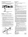
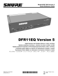
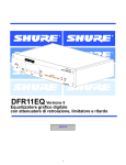
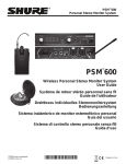
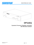
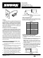
Shure Incorporated
222 Hartrey Avenue
Evanston IL 60202-3696 U.S.A.
Model DRS-10 User Guide
C S 1
2
1
2
3
HARDWARE ADAPTER
SWITCH ASSEMBLY
BACK PANEL
10-POSITION SWITCH ASSEMBLY WIRING DIAGRAM
FIGURE 1
GENERAL
The Shure DRS-10 is a digital switching system that
provides remote scene selection when connected to the
DFR11EQ version 5. The DRS-10 consists of a hardware
adapter, a 10-position switch assembly, and a mounting kit.
The DRS-10 provides remote access to all ten scenes that
can be stored onboard the DFR11EQ. In addition, the
DRS-10 can be customized for use in a three position switch
configuration (not included).
USING CUSTOM SWITCHES
The DRS-10 hardware adapter can be used with a custombuilt switch. Refer to Table 1 for the resistor values needed
in the switch to access the desired scenes.
TABLE 1
SCENE
RESISTOR VALUE
1
97-202 kΩ
2
44-60 kΩ
3
26-32 kΩ
4
17-20 kΩ
IMPORTANT OPERATIONAL INFORMATION
5
11.3-13.6 kΩ
The DRS-10 works only with the DFR11EQ version 5.
The DFR11EQ must be in global scene mode when a switch
assembly is used (refer to the DFR11EQ User Guide). No
switch assembly can be used to control scene selection simultaneously with the software. The DFR11EQ should be
on with the DRS-10 plugged in to execute a scene selection.
6
7.8-9.3 kΩ
7
5.2-6.3 kΩ
8
3.3-4.1 kΩ
Multiple switches can be used to control a DFR11EQ
when wired in parallel (contact Shure’s Applications Department for details). When using multiple devices for scene
control, the most recent scene selected using any device
overrides any previous selection. However, if the power is
cycled (turned off, then on) the DFR11EQ may not default
to the correct scene.
CONNECTING THE HARDWARE ADAPTER TO THE
10-POSITION SWITCH ASSEMBLY
To connect the hardware adapter to the supplied switch
assembly (Figure 1):
1. Determine the distance needed between the mounting
area and the DFR11EQ unit. Trim cable to size.
1.9-2.5 kΩ
0.63-1.1 kΩ
CUSTOMIZING THE DRS-10 FOR USE IN A
3-POSITION SWITCH CONFIGURATION
To connect the hardware adapter to a 3-position switch
(not supplied):
1. Determine the distance needed between the mounting
area and the DFR11EQ unit. Trim cable to size.
NOTE: Cable not supplied. A four-conductor, unshielded cable, such as a Belden 9744, is recommended. The total resistance of the cable run must be
less than 100 ohms.
2. Connect a 3-position switch to the hardware adapter as
shown in Figure 2. The switch should be wired to provide a separate contact between the C (common) terminal and each of the three numbered terminals.
NOTE: Do not use a switch configuration which allows
more than one contact-closure at a time.
C
S
NOTE: Cable not supplied. A two-conductor, unshielded
cable, such as a Belden 8442, is recommended. The total
resistance of the cable run must be less than 100 ohms.
9
10
1
1999, Shure Incorporated
27A8705 (SJ)
3
3. Connect terminal 2 of the switch assembly to terminal
S (switch) on the hardware adapter.
2
2. Connect terminal 1 of the switch assembly to terminal
C (common) on the hardware adapter using cable.
3-POSITION SWITCH WIRING DIAGRAM
FIGURE 2
Printed in U.S.A.
CONNECTING THE HARDWARE ADAPTER
TO THE DFR11EQ
SPECIFICATIONS
Connectors
DFR11EQ connection: Male 9-pin D sub-connector
Cable connection: Screw terminals
Case
Plastic housing
Dimensions
Hardware Adapter: 6.3 cm L x 3.3 cm W x 1.6 cm H
(2.5 in. L x 1.3 in. W x .65 in. H)
Mounting Assembly: 12 cm H x 7.4 cm W x 4.7 cm D
(4.75 in. H x 2.94 in. W x 1.87 in. D)
Cable
Maximum Resistance: 100 ohms series between switch
and hardware adapter
Maximum Length: at least 914 m (3,000 ft.)
Certification
Tested to comply with FCC standards. FOR HOME OR
OFFICE USE. This product complies with part 15 of the
FCC rules. Operation is subject to the following two conditions: (1) this device may not cause harmful interference,
and (2) this device must accept any interference received,
including interference that may cause undesired operation.
Changes or modifications not expressly approved by Shure
Incorporated could void your authority to operate this equipment.
This equipment has been tested and found to comply with
the limits for a class B digital device, pursuant to Part 15 of
the FCC rules. These limits are designed to provide reasonable protection against harmful interference in a residential
installation.
This equipment generates, uses and can radiate radio frequency energy and, if not installed and used in accordance
with the instructions, may cause harmful interference to radio communications. However, there is no guarantee that
interference will not occur in a particular installation. If this
equipment does cause harmful interference to radio or television reception, which can be determined by turning the
equipment off and on, the user is encouraged to try to correct
the interference by one or more of the following measures:
Reorient or relocate the receiving antenna
Increase the separation between the equipment
and the receiver
Connect the equipment into an outlet on a circuit
different from that to which the receiver is connected
Consult the dealer or an experienced radio/TV technician for help
This class B digital apparatus complies with Canadian
ICES-003.
Conforms to European EMC Directive 89/336/EEC: Professional Audio Products Standard EN 55103 (1996); Part
1 (emissions) and Part 2 (immunity). The DRS-10 is intended for use in environments E1 (residential) and E2 (light
industrial) as defined in European EMC standard EN 55103.
It meets the applicable tests and performance criteria found
in the standard for these environments. EMC conformance
is based on the use of recommended cables.
Once the switch assembly and hardware adapter are
connected, plug the hardware adapter of the DRS-10 into
the RS232 port of the DFR11EQ (see Figure 3).
DFR11EQ BACK PANEL
ÑÑ
Ñ
Ñ
ÑÑ
Ñ
Ñ
ÑÑÑ
ÑÑÑÑ
ÑÑ
HARDWARE ADAPTER
CONNECTING THE HARDWARE ADAPTER
FIGURE 3
MOUNTING THE DRS-10 SWITCH ASSEMBLY
TO A WALL
The switching assembly of the DRS-10 may be
mounted using the supplied mounting kit (Figure 4):
1. Mount a standard electrical box into the wall.
2. Place the position ring onto the switch assembly, fitting
the tab of the ring into the desired numbered groove on
the switch assembly.
NOTE: The switch assembly of the DRS-10 can be customized to select up to ten scenes. The location of the
position ring determines how many scenes the switch is
able to access.
3. Peel the plastic sheath from the affixed labels on the wall
plate and hardware adapter. A second 10-position label
is provided for use on custom wall plates.
4. Insert the switch assembly post through the lock washer
and wall plate and attach with the supplied washer and
nut, being careful not to over-tighten the nut.
5. Press the supplied knob onto the switch assembly post.
6. Secure the wire cable to the switch assembly using the
two screw terminals on the back of the assembly, as
previously described in Figure 1.
7. Mount the assembly to the electrical box in the wall.
WALL PLATE
LABEL
SWITCH ASSEMBLY
POSITION RING
WASHER
NUT
LOCK WASHER
KNOB
Replacement Parts
Hardware Adapter Kit . . . . . . . . . . . . . . . . . . . . . RPC601
Switch Assembly Kit . . . . . . . . . . . . . . . . . . . . . . RPC603
Wall Plate Kit . . . . . . . . . . . . . . . . . . . . . . . . . . . . RPC602
DRS-10 WALL MOUNTING ASSEMBLY
FIGURE 4
2