1
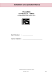
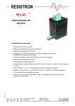
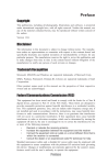
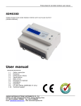
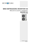
Eaton 93P/E SMALL and LARGE EXTERNAL BATTERY CABINET User's and Installation Guide P-164000427 Eaton 93P/E SMALL and LARGE External Battery Cabinet User's and Installation Guide IMPORTANT SAFETY INSTRUCTIONS SAVE THESE INSTRUCTIONS This manual contains important instructions that you should follow during installation and maintenance of the battery cabinet. Please read all instructions before operating the equipment and save this manual for future reference. This is a product for commercial and industrial application in the second environment. Installation restrictions or additional measures may be needed to prevent disturbances. © 2013 Eaton Corporation All Rights Reserved The contents of this manual are the copyright of the publisher and may not be reproduced (even extracts) without the written approval of Eaton Corporation. Every care has been taken to ensure the accuracy of the information contained in this manual, but no liability can be accepted for any errors or omission. The right to make design modifications is reserved. Contents 1 Safety instructions ........................................................................................................................ 1 1.1 Symbols on the UPS and accessories ................................................................................................... 1 1.2 Conventions used in this manual ........................................................................................................... 2 1.3 General ................................................................................................................................................... 2 1.4 Audience .............................................................................................................................................. 4 1.5 CE marking............................................................................................................................................ 4 1.6 User precautions ................................................................................................................................ 4 1.7 Environment ......................................................................................................................................... 5 1.8 For more information ........................................................................................................................... 5 2 Installation ....................................................................................................................................... 6 2.1 Preparing the Small Battery Cabinet installation .............................................................................. 8 2.2 Preparing the Large Battery Cabinet installation ............................................................................ 10 2.3 Installation with other than 93PM or 93E UPS ................................................................................ 13 3 Maintenance .................................................................................................................................. 14 3.1 Important safety instructions .......................................................................................................... 14 3.2 Performing preventive maintenance .............................................................................................. 15 3.2.1 PERIODIC maintenance ......................................................................................................... 15 3.2.2 ANNUAL maintenance ............................................................................................................ 15 3.2.3 BATTERY maintenance .......................................................................................................... 15 3.3 Recycling the used UPS or batteries ........................................................................................... 15 3.4 Maintenance training........................................................................................................................ 16 4 Technical data ............................................................................................................................... 17 4.1 Standards and regulations .............................................................................................................. 17 4.2 Battery specification .......................................................................................................................... 18 4.3 Environmental specifications .......................................................................................................... 18 5 Warranty ......................................................................................................................................... 19 6 Installation checklist .................................................................................................................... 20 1 Safety instructions 1.1 Symbols on the UPS and accessories The following are examples of symbols used on the UPS or accessories to alert you to important information: RISK OF ELECTRIC SHOCK - Indicates that a risk of electric shock is present and the associated warning should be observed. DANGER CAUTION: REFER TO OPERATOR’S MANUAL Refer to your operator’s manual for additional information, such as important operating and maintenance instructions. CAUTION This symbol indicates that you should not dis- card the UPS or the UPS batteries in the trash. This product involves sealed, lead-acid batteries and must be disposed of properly. For more in-formation, contact your local recycling/reuse or hazardous waste center. Figure 1-1: Recycling batteries symbol This symbol indicates that you should not discard waste electrical or electronic equipment (WEEE) in the trash. For proper disposal, contact your local recycling/reuse or hazardous waste center. Figure 1-2: WEEE symbol P-164000427 Revision 2 SMALL and LARGE BATTERY CABINET User's and Installation Guide 1 1.2 Conventions used in this manual This manual uses these type conventions: • Bold type highlights important concepts in discussions, key terms in procedures, and menu options, or represents a command or option that you type or enter at a prompt. • Italic type highlights notes and new terms where they are defined. Icon Description Information notes call attention to important features or instructions. NOTE 1.3 General The battery cabinet contains components that carry high currents and voltages. The properly installed enclosure is earthed and IP21 rated against foreign objects and is safe to operate. However, only qualified personnel are allowed to install and service the battery cabinet. DANGER This equipment contains LETHAL VOLTAGES. All repairs and service should be performed by AUTHORIZED SERVICE PERSONNEL ONLY. There are NO USER SERVICEABLE PARTS inside the equipment. P-164000427 Revision 2 SMALL and LARGE BATTERY CABINET User's and Installation Guide 2 WARNING • To reduce the risk of fire or electric shock, install this battery cabinet in a temperature and humidity controlled, indoor environment, free of conductive contaminants. Ambient temperature must not exceed 40 °C (104 °F). Do not operate near water or excessive humidity (95 % maximum). The system is not intended for outdoor use. • Ensure all power sources are disconnected before performing installation or service. Power may come from multiple sources. • Ensure system grounding/PE continuity when undertaking installation or service. • Batteries can present a risk of electrical shock or burn from high short-circuit current. • ELECTRIC ENERGY HAZARD. Do not attempt to alter any battery wiring or connectors. Attempting to alter wiring can cause injury. • Do not open or mutilate batteries. Released electrolyte is harmful to the skin and eyes. It may be toxic. • IMPORTANT: the battery may consist of multiple parallel strings, disconnect all strings before installation. CAUTION • Installation or servicing should be performed by qualified service personnel knowledgeable of batteries and required precautions. Keep unauthorized personnel away from batteries. Consider all warnings, cautions, and notes before installing or replacing batteries. DO NOT DISCONNECT the batteries while the UPS is in Battery mode. • Replace batteries with the same number and type of batteries as originally installed. • Disconnect the charging source prior to connecting or disconnecting terminals. • Determine if the battery circuit is inadvertently grounded. If it is, remove the source of the ground. Contacting any part of a grounded battery can cause a risk of electric shock. An electric shock is less likely if you disconnect the grounding connection before you work on the batteries. • Proper disposal of batteries is required. Refer to local codes for disposal requirements. • Do not dispose of batteries in a fire. Batteries may explode when exposed to flame. • Keep the door closed and front panels installed to ensure proper cooling airflow and to protect personnel from dangerous voltages inside the unit. • Do not install or operate the UPS system close to gas or electric heat sources. P-164000427 Revision 2 SMALL and LARGE BATTERY CABINET User's and Installation Guide 3 • The operating environment should be maintained within the parameters stated in this manual. • Keep surroundings uncluttered, clean, and free from excess moisture. • Observe all DANGER, CAUTION, and WARNING notices affixed to the outside of the equipment. 1.4 Audience The intended audience of this manual is people who plan the installation, install, and use the UPS. This manual provides guidelines for checking the delivery, installing, and operating of the battery cabinet. The reader is expected to know the fundamentals of electricity, wiring, electrical components and electrical schematic symbols. This manual is written for a global reader. NOTE Read the manual before operating or working on the UPS system. 1.5 CE marking The product has the CE marking in compliance with the following European directives: • LV Directive (Safety) 2006/95/EC Declaration of conformity with UPS harmonised standards and directives EN 62040-1 (Safety) are available at www.eaton.eu/93PM or by contacting your nearest Eaton office or authorized partner. 1.6 User precautions The only user operation permitted is: • Switch ON or OFF the battery circuit breaker. The user must follow the precautions and only perform the described operations. Any deviation from the instructions could be dangerous to the user or cause accidental loss of load power. WARNING The user is not permitted to open any screws excluding the transparent hatch in front of the battery circuit breaker. Failure to recognize the electrical hazards could prove fatal. P-164000427 Revision 2 SMALL and LARGE BATTERY CABINET User's and Installation Guide 4 1.7 Environment The battery cabinet must be installed and operated according to the recommendations in this manual. Environmental specifications are in chapter 4.3. Ensure proper ventilation. Ensure there are no flammable gases present. Excessive amount of dust in the operating environment of the battery cabinet may cause damage or lead to malfunction. The battery cabinet should always be protected from the outside weather and sunshine. In order to maximize battery service life time, the recommended operating temperature range is from +20 to +25 ºC. WARNING Hydrogen and oxygen gases are emitted from batteries into the surrounding atmosphere during charge, float charge, heavy discharge, and overcharge. Explosive gas mixture may be created if the hydrogen concentration exceeds 4 % by volume in air. Necessary air flow rate for ventilation of battery cabinet location must be ensured. 1.8 For more information Address any inquiries about the UPS and battery cabinet to the local office or agent authorized by the manufacturer. Please quote the part number and the serial number of the equipment. Call your local service representative if help is needed with any of the following: • • • • Scheduling initial startup, Regional locations and telephone number, A question about any of the information in this manual or A question this manual does not answer. P-164000427 Revision 2 SMALL and LARGE BATTERY CABINET User's and Installation Guide 5 2 Installation The battery system provides emergency short-term backup power to safeguard operation during brownouts, blackouts, and other power interruptions. By default, 93PM and 93E UPSs are configured to use valve-regulated lead-acid (VRLA) batteries. For the battery specification, see UPS User’s and Installation Guide. Should there be a need to connect other type of batteries or other energy storage means, a certified service technician should be consulted prior to proceeding with installation. For the 93PM and 93E product lines, there are two different battery cabinets: Small and Large Battery Cabinet. The battery block configuration in the chosen battery cabinet must always match the UPS requirement. Used battery configuration must be inserted into UPS settings during commissioning or start-up. Refer to UPS installation and operation manual for UPS configuration. The allowed battery block configurations for 93PM and 93E UPSs are presented in table 2-1. Table 2-1. Battery block configuration for 93PM and 93E UPSs. 93PM 30-50 kW 93PM 80-200 kW 93E 80-200 kVA 36 blocks (216 cells) 36 (216 cells) or 40 (240 cells) blocks 36 (216 cells), 38 (228 cells) or 40 (240 cells) blocks DANGER Battery strings with different battery quantity and voltage may not be connected in parallel. Make sure that 93PM 30-50kW UPS with internal batteries always uses 36 battery blocks per string. External battery strings must also contain 36 battery blocks per string. Battery cabinet internal power wiring, Battery-to-UPS power wiring and control wiring for integral line-up and match battery cabinets are supplied with the Small Battery Cabinet. Large Battery Cabinet is provided only with battery cabinet internal power wiring and control wiring. There are several cable entries in the battery cabinets. The cabinets can be wired in the following ways: through the left side panel through the right side panel through the back wall through the roof through the bottom (only Large Battery Cabinet) P-164000427 Revision 2 SMALL and LARGE BATTERY CABINET User's and Installation Guide 6 Cable entry to the 93PM UPS is always on the rear or the bottom of the cabinet. In 30-150 kW UPS models the entry is also located on the bottom of the right side panel. Cable entry to the 93E UPS is on the rear or the bottom of the UPS cabinet. For the 80-120 kVA models the bottom cable entry is in the front section of the bottom plate and for the 160-200 kVA models the entry is in the rear section of the bottom plate. NOTE Installation instructions are given in 93PM UPS User’s and Installation Guide Chapter 3.2.2 UPS system power wiring preparation for Eaton 93PM and in 93E UPS Installation & Operation Manual Chapter 4.3 Installing UPS external battery cabinet and battery power wiring for Eaton 93E. Figure 2 -1: 93P/E battery cabinet (Small Battery Cabinet) P-164000427 Revision 2 SMALL and LARGE BATTERY CABINET User's and Installation Guide 7 Figure 2 -2: 93P/E battery cabinet (Large Battery Cabinet) A DC-rated circuit breaker within each cabinet provides protection and service isolation. The battery cabinets use convection cooling to regulate internal component temperature. Air inlets are at the bottom and in Large Battery Cabinet also in the front of the cabinet and outlets are on the rear of the cabinet. Clearance must be allowed in front and rear of each cabinet for proper air circulation. The system must be installed on a level floor suitable for computer or electronic equipment. The system must be installed in a temperature and humidity controlled indoor area free of conductive contaminants. 2.1 Preparing the Small Battery Cabinet installation NOTE The battery cabinet is heavy. If unpacking instructions are not closely followed, the cabinet may tip and cause serious injury. 1. If not already accomplished, use a forklift or other material handling equipment to move the cabinet to the installation area, or as close as possible, before unloading from the pallet. Insert the forklift jacks between the skids on the bottom of the unit. 2. Open the package, remove the front and rear mounting brackets, and attach the ramp to a front edge of the pallet. P-164000427 Revision 2 SMALL and LARGE BATTERY CABINET User's and Installation Guide 8 3. Carefully slide the battery cabinet off the pallet. Now the battery cabinet is ready to be placed aside the UPS. Notes of installation location with 93PM UPS: Both sides can be used for battery cabinet placement but for easier service access to UPS, on the 93PM 30-150 kW UPS right side is preferred, and on the 93PM 160-200 kW left side is preferred. The battery cabinet must be located on the right side of 93PM 30-50 kW UPS cabinet if wiring through cabinet side panels. The 93PM 160-200 kW UPS does not enable wiring through its side panel. Notes of installation location with 93E UPS: Both sides can be used for battery cabinet placement with the 93E UPS but on the left side is preferred with the 80-120 kVA UPS, and on the right side is preferred with the 160-200 kVA UPS to more easily access the battery input terminals through the bottom or the rear entry. 4. Open the battery cabinet and locate the external power wiring shipped along the cabinet. 5. Cables with single insulation are provided with the battery cabinet. These cables can be used for internal wiring, i.e. when the UPS cabinet and the battery cabinet are mounted side by side with no gap in between, and cables are routed directly from cabinet to cabinet. If any length of the cables is routed outside the cabinets then they need to be replaced by double insulated cables or a supplementary insulation needs to be used with cables provided. 6. Apply cable glands and/or plastic pass-through collars accordingly. WARNING Make sure all power sources are disconnected before next steps. 7. Connect the power cables and signal wires to the UPS. No signal wires are connected to 93E UPS. 8. If multiple cabinets are to be used, repeat the steps to the rest of the cabinets and be sure to daisy chain the signal wire harnesses in the next cabinet. Signal wires are daisy chained by cutting the multiple connector and extra length of the cables and connecting them to TB2 terminals 5-8. Look at the Figure 2-6. P-164000427 Revision 2 SMALL and LARGE BATTERY CABINET User's and Installation Guide 9 2.2 Preparing the Large Battery Cabinet installation NOTE The battery cabinet is heavy. If unpacking instructions are not closely followed, the cabinet may tip and cause serious injury. 1. If not already accomplished, use a forklift or other material handling equipment to move the cabinet to the installation area, or as close as possible, before unloading from the pallet. Insert the forklift jacks between the skids on the bottom of the unit. 2. Open the package and remove the two front mounting brackets on the side feet and two rear mounting bolts inside the middle foot. 3. Carefully lift the battery cabinet off the pallet. Now the battery cabinet is ready to be placed aside the UPS. Notes of installation location with 93PM UPS: Both sides can be used for battery cabinet placement but for easier service access to UPS, on the 93PM 30-150 kW UPS right side is preferred, and on the 93PM 160-200 kW left side is preferred. The battery cabinet must be located on the right side of 93PM 30-50 kW UPS cabinet if wiring through cabinet side panels. The 93PM 160-200 kW UPS does not enable wiring through its side panel. Notes of installation location with 93E UPS: Both sides can be used for battery cabinet placement with the 93E UPS but on the left side is preferred with the 80-120 kVA UPS, and on the right side is preferred with the 160-200 kVA UPS to more easily access the battery input terminals through the bottom or the rear entry. 4. Open the battery cabinet and locate the signal wiring shipped along the cabinet. The power cable must be made according to installation requirements. Minimum crosssection area for copper cable is stated on the next table: Table 2-2: Cable cross-section minimum areas UPS power rating (kW) P-164000427 Revision 2 Min Cu cable size (mm2) + and - PE 30 - 50 50 25 60 - 80 70 35 90 - 100 95 50 110 - 150 2 x 70 70 160 - 200 2 x 95 95 SMALL and LARGE BATTERY CABINET User's and Installation Guide 10 5. Select the cable routing out of different options and route the cables to the dedicated connectors inside UPS cabinet. Terminals are located under the circuit breaker and are marked with +, - and a protecting earth designators. 6. Apply cable glands and/or plastic pass-through collars accordingly. WARNING Make sure all power sources are disconnected before next steps. 7. Connect the power cables and signal wires to the UPS. No signal wires are connected to 93E UPS. 8. Battery installation is to be done on-site by authorized and trained service personnel. Batteries are to be installed on the shelves according to the following picture. Ensure you find a correct wiring instruction included into the cabinet and follow it. Figure 2 -4: Battery mounting on the shelves P-164000427 Revision 2 SMALL and LARGE BATTERY CABINET User's and Installation Guide 11 Cable connection to battery poles is to be done as follows: Figure 2 -5: Cable connection on b attery poles 9. If multiple cabinets are to be used, repeat the steps for the rest of the cabinets and in 93PM system be sure to daisy chain the signal wire harnesses in the next cabinet. 93E system does not use signal wiring. Signal wires are daisy chained by cutting the multiple connector and extra length of the cables and connecting them to TB2 terminals 5-8. Look at the Figure 2-6. Figure 2 -6: Signal wiring of Large and Small Battery Cabinet . P-164000427 Revision 2 SMALL and LARGE BATTERY CABINET User's and Installation Guide 12 2.3 Installation with other than 93PM or 93E UPS Other UPSs may not be fully compatible with 93P/E External Battery Cabinet. Check UPS manual for the requirements for the external battery supply. P-164000427 Revision 2 SMALL and LARGE BATTERY CABINET User's and Installation Guide 13 3 Maintenance The components inside the cabinet are secured to a sturdy metal frame. All repairable parts and assemblies are located for easy removal, with very little disassembly. This design allows authorized service personnel to perform routine maintenance and servicing quickly. You must schedule periodic performance checks of your UPS system to keep it running properly. Regular routine checks of operation and system parameters enable your system to function efficiently for many trouble-free years. 3.1 Important safety instructions Remember that your UPS system is designed to supply power EVEN WHEN DISCONNECTED FROM THE UTILITY POWER. The UPS module interiors are unsafe until the DC power source is disconnected and the electrolytic capacitors are discharged. After disconnecting the utility power and the DC power, authorized service personnel should wait at least five minutes for capacitor bleed-off before attempting internal access to the UPS module. CAUTION • Servicing and maintenance should be performed by qualified service personnel only. • LETHAL VOLTAGE PRESENT. This unit should not be operated with the cabinet doors open or protective panels removed. Do not make any assumptions about the electrical state of any cabinet in the UPS system. Since each battery string is an energy source in itself, opening the battery circuit breaker does not de- energize the voltage within the battery string. DO NOT ATTEMPT TO ACCESS ANY INTERNAL AREA OF THE BATTERY STRING YOURSELF. VOLTAGES ARE ALWAYS PRESENT IN THE BATTERY STRING. If you suspect that a battery string needs service, you should contact your service representative. If the string requires service, refer to the battery manufacturer’s operating manual for instructions on battery maintenance or contact your service representative. Observe these precautions when working on or around batteries: Remove watches, rings, or other metal objects. Use tools with insulated handles. Wear rubber gloves and boots. Do not lay tools or metal parts on top of batteries or battery cabinets. Disconnect the charging source prior to connecting or disconnecting terminals. Determine if the battery is inadvertently grounded. If it is, remove the source of the ground. Contact with any part of a grounded battery can result in electrical shock. The likelihood of such shock is reduced if such grounds are removed during installation and maintenance. P-164000427 Revision 2 SMALL and LARGE BATTERY CABINET User's and Installation Guide 14 When replacing batteries, use the same number of sealed, lead-acid batteries. Proper disposal of batteries is required. Refer to your local codes for disposal requirements. 3.2 Performing preventive maintenance The battery cabinets require very little preventive maintenance. However, the UPS system should be inspected periodically to verify that the units are operating normally and that the batteries are in good condition NOTE Work on energized circuit must be performed only by authorized personnel. 3.2.1 PERIODIC maintenance Periodic inspections of the UPS should be made to determine if components, wiring, and connections exhibit evidence of overheating. Particular attention should be given to bolted connections. Maintenance procedures should specify that the bolted connections be re-torqued. 3.2.2 ANNUAL maintenance Annual preventive maintenance should be performed only by authorized service personnel familiar with maintenance and servicing of the UPS system. Contact your service representative for more information about service offerings. 3.2.3 BATTERY maintenance Contact your service representative for battery maintenance. Battery replacement and maintenance should be performed only by authorized service personnel. 3.3 Recycling the used UPS or batteries Before scrapping UPS or its battery cabinet, the battery bank must be removed. Local requirements must be followed in battery recycling or discard. The removal of batteries is allowed only by authorized service personnel due to high energy and voltage. Do not discard waste electrical or electronic equipment in the trash. For proper disposal, contact your local collecting/recycling/reuse or hazardous waste center and follow the local legislation. P-164000427 Revision 2 SMALL and LARGE BATTERY CABINET User's and Installation Guide 15 These symbols indicate on a product Figure 3 -1: WEEE symbol Use proper local collecting centers meeting local legislation when handling waste of electrical and electronic equipment. DANGER HAZARDOUS MATERIALS. Batteries may contain HIGH VOLTAGES, and CAUSTIC, TOXIC and FLAMMABLE substances. Batteries can injure or kill people and damage equipment if used improperly. DO NOT DISCARD unwanted batteries or battery material in the public waste disposal system. Follow ALL applicable, local regulations for storage, handling and disposal of batteries and battery materials. Figure 3 -2: Recycling batteries symbol 3.4 Maintenance training For more information about training and other services, contact your Eaton representative. P-164000427 Revision 2 SMALL and LARGE BATTERY CABINET User's and Installation Guide 16 4 Technical data For complete technical specification, contact your Eaton representative. Due to continuous product improvement programs, specifications are subject to change without notice. 4.1 Standards and regulations Safety: IEC 62040-1, IEC 60950-1 Performance & tests: IEC 62040-3 Environmental: IEC 62430 RoHS: 2011/65/EU, EN50581 REACH: 2006/1907/EC WEEE: 2012/19/EU Batteries: 2006/66/EC Packaging: 94/62/EC Table 4 -1: Standards and regulations P-164000427 Revision 2 SMALL and LARGE BATTERY CABINET User's and Installation Guide 17 4.2 Battery specification Battery type VRLA, 12 VDC 93PM 30-50 kW units: 1) 36 blocks, 216 cells per battery string, 2V per cell. 93PM 80-200 kW units: 1) 36 blocks, 216 cells per battery string, or 2) 40 blocks, 240 cells per battery string, 2V per cell. Battery quantity 93E 80-200 kVA units: 1) 36 blocks, 216 cells per battery string, or 2) 38 blocks, 228 cells per battery string, or 3) 40 blocks, 240 cells per battery string, 2V per cell. Note! Battery strings with different battery quantity and voltage must not be connected in parallel! Battery Voltage 432 V (36 blocks) or 456V (38 blocks) or 480 V (40 blocks) Table 4 -2: Battery specification 4.3 Environmental specifications Recommend storage temperature range Ambient operating temperature range From -25 °C to +25 °C in the protective package From +5 °C to +40 °C Recommended ambient operating temperature range From +20 °C to +25 °C Relative humidity range 5 to 95 % no condensation allowed Table 4 -3: Environmental specifications P-164000427 Revision 2 SMALL and LARGE BATTERY CABINET User's and Installation Guide 18 5 Warranty The product is warranted against defects in materials and workmanship for a period of twelve (12) months from its original date of purchase. The local office or distributor may grant a warranty period different to the above. Please refer to local terms of liability as defined in the supply contract. The UPS manufacturer is not responsible for Any costs resulting from a failure if the installation, commissioning, repair, alternation, or ambient conditions of the equipment do not fulfil the requirements specified in the documentation delivered with the unit and other relevant documentation. Equipment subjected to misuse, negligence or accident. Equipment comprised of materials provided or designs stipulated by the purchaser. The warranty is only valid if the installation inspection and initial start-up of the UPS unit is carried out by a service engineer approved by Eaton. Service and maintenance of the UPS shall also be performed only by a service engineer approved by Eaton. Otherwise the warranty will be voided. If the product fails to meet its published specifications due to a defect in material and workmanship, covered by this warranty, the seller will repair or replace the warranted product. Such repair or replacement will be made by Eaton or by a service provider approved by Eaton. Repair or replacement during the warranty period does not extend the original warranty. Warranty does not cover taxes, which will be due in connection with replacement or repair of the product. Batteries are warranted against failures in material and workmanship, not against the normal aging and reduction of ampere-hour capacity. The product storage environment has to meet manufacturer's specifications, failure to do this will cause the warranty to be voided. Under no circumstances shall the manufacturer, its suppliers or subcontractors be liable for special, indirect, incidental or consequential damages, losses or penalties. The technical data, information and specifications are valid at the time of printing. The UPS manufacturer reserves the right to modifications without prior notice. P-164000427 Revision 2 SMALL and LARGE BATTERY CABINET User's and Installation Guide 19 6 Installation checklist All packing materials and restraints have been removed from each cabinet. Each cabinet in the UPS system is placed in its installation location. A cabinet grounding/mounting kit is installed between any cabinets that are bolted together. All conduits and cables are properly routed to the UPS and any ancillary cabinets. All power cables are properly sized and terminated. Neutral conductors are installed as per requirements. A ground conductor is properly installed. Battery cables are terminated and connected to battery connectors. Battery Shunt trip and Aux contact signal wiring is connected from the UPS to the battery cabinet. Note: 93PM only! Room ventilation and air conditioning equipment are installed and operating correctly. The area around the installed UPS system is clean and dust-free. (It is recommended that the UPS be installed on a level floor suitable for computer or electronic equipment.) Adequate workspace exists around the UPS and other cabinets. Adequate lighting is provided around all UPS equipment. A 230 VAC service outlet is located within 7.5 meters of the UPS equipment. Alarm relays and signal inputs are wired appropriately. (OPTIONAL) A remote battery disconnect control is mounted in its installation location and its wiring is terminated inside the UPS and battery cabinet. (OPTIONAL) Accessories are mounted in installation locations and wiring is terminated inside the UPS cabinet. (OPTIONAL) Startup and operational checks are performed by an authorized Eaton Customer Service Engineer P-164000427 Revision 2 SMALL and LARGE BATTERY CABINET User's and Installation Guide 20 P-164000427 Revision 2 SMALL and LARGE BATTERY CABINET User's and Installation Guide 21