1
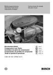
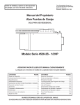
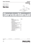
DM2.Man.08.00 11/29/00 8:28 PM Page 2
TM
Operator’s Manual
Model DM2
Digital Multimeter
• Manual de Instrucciones
Digital Multimeter/Multi Tester
¤
DM2.Man.08.00 11/29/00 8:28 PM Page 1
WARRANTY
The DM2 Multimeter is warranted against any defects of material or
workmanship within a period of one (1) year following the date of purchase of the multimeter by the original purchaser or original user.
Any multimeter claimed to be defective during the warranty period
should be returned with proof of purchase to an authorized Wavetek
Meterman Service Center or to the local Wavetek Meterman dealer or
distributor where your multimeter was purchased. See maintenance
section for details. Any implied warranties arising out of the sale of a
Wavetek Meterman multimeter, including but not limited to implied
warranties of merchantability and fitness for a particular purpose, are
limited in duration to the above stated on (1) year period. Wavetek
Meterman shall not be liable for loss of use of the multimeter or other
incidental or consequential damages, expenses, or economical loss
or for any claim or claims for such damage, expenses or economical
loss.
Some states do not allow limitations on how long implied warranties
last or the exclusion or limitation of incidental or consequential damages, so the above limitations or exclusions may not apply to you.
This warranty gives you specific legal rights, and you may also have
other rights which vary from state to state.
CONTENTS
Warning and Precautions
Unpacking and Inspection
Operation
Specifications
Maintenance
Repair
2
3
3
7
8
9
–1–
DM2.Man.08.00 11/29/00 8:28 PM Page 2
SYMBOLS
Direct current
Alternating current
Ground connection
Attention! Refer to Operating Instructions
Dangerous voltage may be present at terminals
WARNING AND PRECAUTIONS
The DM2 is not recommended for high voltage industrial use applications, but for use with low energy circuits to 500VAC or 1000VDC,
or high energy circuits only to 250 VAC or VDC. ■ Do not exceed the
maximum overload limits per function (see specifications) nor the
limits marked on the instrument itself. ■ Exercise extreme caution
when: measuring voltage >20 V / / current >10mA / / AC power line
with inductive loads / / AC power line during electrical storms / / current, when the fuse blows in a circuit with open circuit voltage > 600
V / / servicing CRT equipment. ■ Inspect DMM, test leads and
accessories before every use. Do not use any damaged part. ■ Never
ground yourself when taking measurements. Do not touch exposed
circuit elements or probe tips. ■ Always measure current in series
with the load – NEVER ACROSS a voltage source. Check fuse first.
■ Never replace a fuse with one of a different rating. ■ Do not operate instrument in an explosive atmosphere.
–2–
DM2.Man.08.00 11/29/00 8:28 PM Page 3
ACCESSORIES
VC12
RTL25
Vinyl Carring Case
Replacement Test Leads
UNPACKING AND INSPECTION
Upon removing your new digital multimeter (DM2) from its packaging, you should have the following items:
1.
2.
3.
4.
5.
6.
DM2 Digital Multimeter
Test Lead Set (1 black, 1 red)
9 Volt Battery (in meter)
Warranty Card
Operator’s Manual
One Spare Fuse (0.8A/250V)
If any of the above items are missing or are received in a damaged
condition, please contact the distributor from whom you purchased
the unit.
Familiarization (Fig.1)
1.
2.
3.
4.
5.
Function/Range Switch: Selects the Function and Range desired.
COM Input Terminal: Ground input connector. 500V (DC + AC
Peak) Maximum voltage between COM and earth ground.
V Ω Input Terminal: Positive input connector for voltage, resistance,
and diode test. Maximum input rating is 1000VDC, 500VAC.
200mA Input Terminal: Positive input connector for up to 200mA
current. Fused.
Lo Bat: Indicates batter is low.
OPERATING INSTRUCTIONS
Range Selection
If magnitude to be measured is unknown, always start with the highest range.
PRECAUTION!
Overload Condition: Range overload is indicated by a "1." Or by a "1." In the display with all other digits blanked. This is normal in the
ohms range when the leads are not connected to anything. In all other
situations, the user must take immediate steps to remove the cause of
–3–
DM2.Man.08.00 11/29/00 8:28 PM Page 4
the overload condition from the meter. Select the next higher range
until a value is displayed. If overload condition still exists in the
highest range, remove test leads from the measurement setup as it is
beyond the range of the meter.
5
1000
V
OFF
DM2
V
500
20
200
200
u
20
2
2m
200
m
20m
200
m
2000
k
A
200k
1
20k
2k
200
4
FUSED 200mA
V
3
COM
2
1000V
500V
MAX
Fig.1
Model DM2
–4–
DM2.Man.08.00 11/29/00 8:28 PM Page 5
VOLTAGE MEASUREMENT
1. Turn off power to the device under test and discharge all capacitors.
2. Set the Function/Range switch to the desired voltage type (AC or DC)
range.
3. Plug the black test lead into the COM jack on the DMM and connect
the test lead point to a grounded point (the reference point for measurement of voltage).
4. Plug the red test lead into the V jack on the DMM and connect the test
lead point to the circuit where a voltage measurement is required.
Voltage is always measured in parallel across a test point.
5. Turn on power to the circuit/device to be measured and make the voltage measurement. Reduce the range setting if set too high until a satisfactory reading is obtained.
6. After completing the measurement, turn off power to the circuit /
device under test, discharge all capacitors and disconnect the DMM
test leads.
CURRENT MEASUREMENT
1. Turn off power to the device under test and discharge all capacitors.
2. Set the Function/Range switch to the desired current range.
3. Plug the black test lead into the COM jack on the DMM and connect
the test return branch for the current to be measured.
4. Plug the red test lead into the 200mA current jack of the DM2.
Current measurements are always made with the meter in series with
the test branch. The circuit must be broken and the meter put in series
by placing the red test lead point to the test node for current.
5. Turn on power to the circuit/device under test and make the current
measurement. Reduce the range setting if set too high until a satisfactory reading is obtained.
6. After completing the measurement, turn off power to the circuit/device
under test, discharge all capacitors, disconnect the DMM test leads
and re-connect the circuit branch.
Note: The current jack has a protective fuse installed to protect the
meter from damage and the user from harm if a current larger
than specified is applied at the input. If the quick acting fuse
blows, replace with a like fuse.
–5–
DM2.Man.08.00 11/29/00 8:28 PM Page 6
RESISTANCE MEASUREMENTS
1. Turn off any power to the resistance to be measured. Discharge any
capacitors. Any voltage present during a resistance measurement will
cause inaccurate readings and could damage the meter if exceeding
the overload protection of 500VDC or AC.
2. Set the Function/Range switch to the desired resistance range.
3. Plug the black test lead into the COM jack on the DMM and connect
the test lead point to one end of the resistor,
4. Plug the red test lead into the Ω jack on the DMM and connect the
test lead point to the other end of the resistor.
5. Adjust the Function/Range switch to the resistance range that gives the
most accurate measurement reading.
Note: Test lead resistance can interfere when making low resistance
measurements and should be subtracted from resistance readings
for accuracy. Select 200Ω range and make a firm contact
between the two test lead points (short them together). The display value is the test lead resistance to be subtracted from resistance reading. Open circuits will be displayed as an overload
condition.
DIODE TEST
Diode Test checks the forward bias of diode function.
1. Turn off power to the device under test and discharge all capacitors.
2. Set the Function/Range switch to
3. Plug the black test into the COM jack on the DMM and connect the
test lead point to the cathode of the diode.
4. Plug the red test lead into the V Ω jack on the DMM and connect the
test lead point to the anode of the diode. The meter’s display indicates
the forward voltage drop (approximately 0.7V for silicone diode or
0.4V for germanium diode). Meter will display overload condition for
an open diode
5. Reverse the test lead connections to the diode to perform a reverse
bias test of the diode junction. A "1" (over-range) indicates a good
diode because a good diode junction has practically infinite resistance.
Notes: Overload conditions for both reverse and forward bias tests indicate an open diode. A low voltage reading for both bias tests indicates
a shorted diode. If the diode is shunted by a resistor of 1000 ohms or
less, it must be removed from the circuit before taking the measurement.
–6–
DM2.Man.08.00 11/29/00 8:28 PM Page 7
Bipolar transistor junctions may be tested in the same manner described
above as emitter-base and base-collector junctions are diode junctions.
SPECIFICATIONS
General Specifications*
Display:
Polarity:
Zero:
Over-range:
Low Battery:
Display Update:
Operating Temp:
Storage Temp:
tery
Accuracy:
Power:
Battery Life:
Dimensions:
Weight:
Accessories:
3 1/2 digit LCD, 1999 count.
Automatic, positive implied, negative
indicated.
Automatic
(1) or (-1) is displayed.
is displayed in the LCD when the battery
voltage drops below accurate operating
level.
3 per second, nominal.
0˚C to 50˚C, 0 to 70% Relative Humidity
-20˚C to 60˚C, 0 to 80% R.H. with batremoved from meter.
Stated accuracy at 23˚C 5˚C, <75% R.H.
Stated 9 volt battery NEDA1604, JIS
006P, IBC 6F22.
200 hrs (Alkaline), 150 hours (CarbonZinc)
(H x W x D) 4.7 x 2.7 x 1.1 inches (11.9 x
639 x 2.8 cm)
5.5 ounces (156 grams)
One pair test leads, one spare fuse, bat
tery, and Operator’s Manual.
*Specifications subject to change without notice
ELECTRICAL SPECIFICATIONS
DC Volts
Ranges:
Accuracy:
Input Impedance:
Resolution:
OL Protection:
200mV Range:
Other Ranges:
200mV, 2V, 20V, 200V, 1000V
0.8% RDG + 1 Digit
1MΩ
100mv
350VAC RMS/500VDC for 15 seconds
500VAC RMS/1000VDC for 60 seconds
–7–
DM2.Man.08.00 11/29/00 8:28 PM Page 8
AC Volts
Ranges:
Accuracy:
OL Protection:
200V, 500V
1.2% RDG + 10 Digits
500VAC RMS/500VDC
DC Current
Ranges:
Resolution:
Accuracy:
Voltage Burden:
OL Protection:
200 A, 2mA, 20mA, 200mA
100nA
1.2% RDG + 1 Digit
350mV max
.8A/250V fuse
Resistance
Ranges:
Accuracy:
Other Ranges:
OL Protection:
200Ω, 2kΩ, 20kΩ, 200kΩ, 2MΩ
200Ω Range:
1/8% RDG + 4 Digits
1.2% RDG + 2 Digits
500VAC/VDC all ranges
Diode Test
Test Current:
Test Voltage:
1.0 0.6mA
3.2VDC max
MAINTENANCE
WARNING!
To prevent electrical shock hazard, turn off the multimeter and any device
or circuit under test and disconnect the test leads before removing the
battery hatch to the rear cover.
Troubleshooting
If there appears to be a malfunction during the operation of the meter, the
following steps should be performed in order to isolate the cause of
the problem:
1. Check the battery.
2. Review the operating instructions for possible mistakes in operating
procedure.
3. Inspect and test the test probes for a broken or intermittent connection.
–8–
DM2.Man.08.00 11/29/00 8:28 PM Page 9
4. Inspect and test the fuse. If it is necessary to replace the fuse, be sure
to install on of the proper current value. (See fuse replacement
below).
Battery Replacement
1. Remove the battery cover by gently sliding it toward the bottom of the
meter.
2. Remove and disconnect the old battery from the meter and replace
with a new NEDA type 1604 9 volt battery. Wind the excess lead
length once around the battery clip. Install the battery and replace the
battery cover.
Fuse Replacement
1. Remove the battery cover by gently sliding it towards the bottom of the
meter.
2. Remove the old fuse and replace with a new fuse of the proper rating.
The DM2 requires a 0.8A/250V quick-acting fuse, 5 x 20 mm.
WARNING!
To prevent fire, use a replacement fuse of the proper rating as shown
above.
Cleaning the Meter
Use only mild detergent and warm water to clean the meter. Do not use
aromatic hydrocarbons or chlorinated solvents.
REPAIR
Read the warranty located at the front of this manual before requesting warranty or non-warranty repairs. For warranty repairs, any multimeter claimed to be defective can be returned to any Wavetek
Meterman authorized distributor or to a Wavetek Meterman Service
Center for an over-the-counter exchange for the same or like product.
Non-warranty repairs should be sent to a Wavetek Meterman Service
Center. Please call Wavetek Meterman or enquire at your point of
purchase for the nearest location and current repair rates. All multimeters returned for warranty of non-warranty repair or for calibration
should be accompanied by the following information or items: company name, customer’s name, address, telephone number, proof of
–9–
DM2.Man.08.00 11/29/00 8:28 PM Page 10
purchase (warranty repairs), a brief description of the problem or the
service requested, and the appropriate service charge (for non-warranty repairs). Please include the lest leads with the meter. Service
charges should be remitted in the form of a check, a money order,
credit card with expiration date, or a purchase order made payable to
Wavetek Meterman or to the specific service center. For minimum
turn-around time on out-of-warranty repairs please phone in advance
for service charge rates. The multimeter should be shipped with
transportation charges prepaid to one of the following addresses or to
a service center
In U.S.A
Wavetek Meterman
1420 75th Street SW
Everett, WA 98203
Tel: 1-877-596-2680
Fax: 425-446-6390
in Canada
Wavetek Meterman
400 Britannia Rd. E.Unit #1
Mississauga, ON L4Z 1X9
Tel: (905) 890-7600
Fax: (905) 890-6866
in Europe
Wavetek Meterman
52 Hurricane Way
Norwich, NR6 6JB, U.K.
Tel: int + 44-1603-404824
Fax: int + 44-1603-482409
The instrument will be returned with the transportation charges paid
by Wavetek Meterman.
– 10 –
DM2.Man.08.00 11/29/00 8:28 PM Page 11
TM
Manual de Instrucciones
Model DM2
Digital Multimeter
Digital Multimeter/Multi Tester
¤
DM2.Man.08.00 11/29/00 8:28 PM Page 12
GARANTÍA
El multímetro DM2 está garantizado contra cualquier defecto de material o de mano de obra durante un periodo de un (1) año contado a
partir de la fecha de adquisición. Se explican los detalles relativos a
reparaciones en guarantía en la sección de "Mantenimiento y
Reparación".
Cualquier otra garantía implícita está también limitada al período citado de un (1) año. Wavetek Meterman no se hará responsible de pérdidas de uso del multímetro, ni de ningún otro daño accidental o consecuencial, gastos o pérdidas económicas, en ninguna reclamación a
que pudiera haber lugar por dichos daños, gastos o pérdidas
económicas.
CONTENIDOS
Información de seguridad
Puntas de prueba y accesorios
Familiarización con el instrumento
Procedimientos de medida
Especificaciones
Mantenimiento y reparación
13
13
13
14
17
19
SIGNIFICADO DE LOS SÍMBOLOS
Corriente continua
Corriente alterna
Conexión a tierra
¡
Atención! Consulte las Instrucciones de Uso
Puede haber tensión peligrosa en los terminales
– 12 –
DM2.Man.08.00 11/29/00 8:28 PM Page 13
ADVERTENCIAS Y PRECAUCIONES
■ No debe utilizarse este instrumento sobre hilos sin aislar a tensiones superiores a 500 V CA o 1000 V DC. ■ No supere nunca los
límites de entrada para las diferentes funciones (vea
Especificaciones), ni los límites marcados en el instrumento. ■
Tenga especial cuidado: al medir tensión >20 V // tensión de red de
CA con cargas inductivas // tensión de red de CA durante tormentas
eléctricas // mien-tras trabaja con pantallas TRC ■ Inspeccione
siempre el multímetro, las puntas de prueba y los accesorios antes de
cada uso. No utilice ningún componente dañado. ■ Nunca se ponga
Ud. a tierra cuando esté tomando medidas. No toque nunca circuitos
expuestos ni partes metálicas. Mantenga su cuerpo aislado de tierra.
■ No utilice el instrumento en ambientes potencialmente explosivos.
ACCESORIOS OPCIONALES
VC12
RTL25
Estuche de vinilo acolchado
Puntas de pruebe de repuesto
PREPARACIÓN DEL MULTÍMETRO POR SU USO – DESEMBALAJE
El embalaje debe contener:
1. Multímetro modelo DM2
2. Puntas de prueba, una roja y una negra
3. Pila instalada en el medidor
4. Tarjeta de garantía
5. Manual de instrucciones
6. Un fusible de repuesto (0.8A/250V)
Conocimiente (Fig2)
1. Selector de Función/Escala: para selección de funciones y escalas
deseadas
2. Entrada COM (negra): entrada comun (negativa) para todas las medidas
3. Entrada V Ω (roja): Entrada positiva para tensión, resistencia y comprobación de diodos
4. Entrada 200mV: Entrada positiva desde 200mA corriente con fusible
5. Pila baja: Indica que se cambie la pila
– 13 –
DM2.Man.08.00 11/29/00 8:28 PM Page 14
FUNCIONAMIENTO DEL MEDIDOR
Selección de la Escala
Si no conoce la mangitud de la escala que van a medir, selecione en
el primer lugar la escala más alta.
ADVERTENSIA
Indicación sobrecarga: La sobrecarga de escala se indica mediante
de un "1." o "-1." en el visualizador. Para eliminar la causa de sobrecarga, seleccione un escala más alta. Si ya está en la escala más alta,
interumpa la medida. La indicacíon de sobrecarga es normal en
medida de OHMS (_) cuando el circuito está abierto o la resistencia
es demasiado alta.
5
1000
V
OFF
DM2
V
500
20
200
200
u
20
2m
2
200
m
20m
200
m
2000
k
1
A
200k
20k
2k
200
4
FUSED 200mA
V
3
COM
2
1000V
500V
MAX
Fig 2
Model DM2
– 14 –
DM2.Man.08.00 11/29/00 8:28 PM Page 15
MEDIDAS DE TENSION CC Y CA (DCV Y ACV)
1. Antes de conectar o desconectar las puntas de prueba a/de un circuito, simpre apague el dispositivo o circuito semetido a prueba y
descarge los condensadores.
2. Selecione la Funcion/Escala a la medida CC o CA deseada.
3. Conecte la punta de prueba negra a COM, entrada común o "negativa"
para todas las medidas.
4. Conecte la punta de prueba roja a V Ω. Toque con las puntas de
prueba los puntos de tensión (en paralelo con el circuito.
5. Conecte la alimentacion del circuito sometido a prueba y hace la
medida. Si la escala es demasiada alta, reducela hasta que obtiene
una lectura satisfactoria.
6. Despues to obteniendo la medida, apage el cirucito dispositivo o
sometido a prueba y descarge todos los condsensadores y desconecte
las puentas de prueba.
MEDIDAS DE CORRIENTE CC (DCA)
1. Apage siempe el dispoitivo o circuito sometido a prueba y descarge
todos los condensadores.
2. Ponge el selector de funcion a la escala deseada de corriente.
3. Conecte la punta de prueba negra a la entrada de COM on el multimetro.
4. Conecte la punta de prueba roja a 200mA. Abre el circuito sometido a
medición y conecte las puntas de prueba en serie con la carga
5. Conecte la alimentacion del circuito sometido a prueba. Si las escala
es demasiada alta, reducela hasta obtener una lectura satisfactoria
6. Asegurese que no hay corriente aplicada y descarge los condensadores
Nota: La entrada de corriente tiene un fusible de proteccion que debe
ser sustituendo solamente con un fusible precisamente del mismo
tipo.
MEDIDAS DE RESISTENCIA
1. Asegurese de que no hay tensión aplicada a la resistencia y descarge
los condensadores. La presencia de tensión causará imprecisión en
las medidas de resistencia.
2. Ponge el selector de función/escala en la posición deseada de Ω.
3. Conecte la punta de prueba negra a COM y conectela a un resistor
– 15 –
DM2.Man.08.00 11/29/00 8:28 PM Page 16
4. Conecte la punta de prueba roja a Ω conectela a otra punta del resistor
5. Ajuste la función/escala que le da la lectura más precisa
Nota: Para valores bajos de resistencia, mida en primer lugar la
resistencia de las puntas de prueba, uniendo los extremos de estas y
restando el valor de la lectura obtenia. Un circuito abierto se indicará
como condición sobrecarga.
COMBROBACION DE DIODOS
En esta prueba se mide la polarización de la unión del diodo.
1. Desconecte la alimentación del diodo que va a medir y descarge los
condensadores.
2. Ponge el selctor de función/escala a INSERT PROPER SYMBOL
3. Conecte la punta de prueba roja a la entrada V Ω la negra a la entrada
COM
4. Aplique la punta de prueba roja al anodo del diode y la negra al catodo. El visualizador indica la caída de tension directa (aprox. 0.7V para
diodos de silicio o 0.4V para diodos de germanio)
5. Invierta la conexión de las puntas de prueba para verificar la polarización inversa del diodo. Una indicación "1" de sobrecarga significa
que el diodo está de buen estado
Nota: La condición de sobrecarga en ambos sentidos indica un diodo
abierto. Un valor bajo en ambos sentidos indica un diode cortecircuitado. Si el diodo tiene en paralelo una resistencia menor or igual
de 1000 Ω, deberá extraerlo del circuito antes de hacer la medida.
Las uniones de un transistor bipolar pueden comprobarse de la misma
forma que los diodos.
– 16 –
DM2.Man.08.00 11/29/00 8:28 PM Page 17
ESPECIFICATIONES
Especificationes Generales
Visualizador:
Indicación de polaridad:
LCD de 31/2 digitos, 1999 cuentas
automatica, positiva implicada,
negativa indicada
Ajuste de zero:
Automatico
Indicación subrecarga:
Aparece (1) or –(1) en el visual
izador
Indicación de pila baja:
- +. Cambie la pila immediata
mente
Frequencia de refresco de la lecture: tres veces al secundo, nominal
Temperatura de funcionamiento:
0 a 50˚C, 0 a 70% H.R.
Temperatura de almacenamiento:
0-20 a 60˚C, 0 a 80% R.H. sin
pila
Excactitud:
23˚C ±5˚C, ≤75% R.H.
Alimentación:
Pila normal de 9V, NEDA 1604, JIS
006P, IEC 6F22
Duración de la pila (tipica):
200 horas (alcalina), 150 horas
(carbon-zinc)
Dimensiones:
11.9 x 6.9 x 2.8 cm
Peso:
156 g
Accessorios incluidos:
Puntas de prueba, fusible de
repuesto, pila y manual de instruc
ciones
ESPECIFICACIONES ELÉCTRICAS
Voltos CC
Escala:
Precision:
Impedancia de entrada:
Resolución:
Protección sobrecarga:
200mV, 2V, 20V, 200V, 1000V
±0.8% de las escalas + 1 digito
1MΩ
100mV
Escala 200mV – 350VCA
et/500VCC por 15 secundos, otros
escalas – 500VCA/RMS/1000VCC
por 60 secundos
– 17 –
DM2.Man.08.00 11/29/00 8:28 PM Page 18
Voltos CA
Escalas:
Precisión:
Protección subrecarga:
200V, 500V
±1.2%de la lectura, +10 digitos
500VCA RMS/500VCC
Corriente CC
Escalas:
Resolución:
Precisión:
Lastre de tensión:
Protección sobrecarga:
200mA, 2mA, 20mA, 200mA
100nA
±1.2% de la lectura, +10 digitos
350V maximo
.8A/fusible de 250V
Resistencia
Escalas:
Precisión:
200Ω, 2kΩ, 20kΩ, 200kΩ. 2MΩ
Escala de 200Ω - ±1.8%de la lec
tura, + 4 digitos,
otros escalas - ±1.2% de la lectura,
+ 2 digitos
Proteción sobrecarga todas las escalas: 500VCC o CA
Prueba de diodos
Corriente de prueba:
Tension de medida:
1.0 ± 0.6mA
3.2VCC maximo
– 18 –
DM2.Man.08.00 11/29/00 8:28 PM Page 19
MANTENIMIENTO
ADVERTENCIA
Para evitar el peligro de descarga electrica, apague el multímetro y
desconecte las puntas de prueba antes de abrir la tapa posterior.
Localización de Averias
Para identificar la causa de un problemo, hace lo siguente:
1. Compruebe la pila
2. Consulte el manual de instrucciones
3. Inspecione las puntas de prueba si que hay una conexión rota o intermetiente
4. Inspecione el fusible. Cambie el fusible abierto por otro nuevo de
mismo valor
Cambio de la Pila
1. Quite los dos tornillos y separe la tapa posterior del medidor
2. Extraiga la pila y cambiela por otra equivalente de tipo NEDA 1604.9.
Vuela a montar el medidor
Cambio del Fusible
1. Quite los dos tornillos y separe la tapa posterior del medidor
2. Sustituye el fusible abierto por otro equivalente
ADVERTENSIA
La utilizacion de un fusible incorecto puedo causar graves daños personales
Limpiar el Medidor
Para limpiar la carcasa del medidor, se puede utilizar una solución
suave de agua y detergente. Aplique con un paño suave y deje secar
antes de usar el medidor.
– 19 –
DM2.Man.08.00 11/29/00 8:28 PM Page 20
REPARACIÓN
Lea las condiciones de grantía, al principio de este manual, antes de
solicitar cualquier reparación dentro o fuera de garantía. Si la
reparación es en garantía, puede llevar el multímetro defectuoso a
cualquier Distribuidor Autorizada o Centro de Servicio de Wavetek
Meterman, donde le cambiarán en mano el producto por otro igual o
similar. Para reparaciones fuera de garantía deberá enviar el
multímetro a un Centro de Servicio Wavetek Meterman. En Wavetek
Meterman, or en su Distribuidor o punto de venta, le indicarán el
Centro de Servicio más próximo y las tarifas de reparación. La documentación que acompañe a todo multímetro enviado para
reparación debe incluir los siguentes datos: nombre de la empresa,
persona de contacto, dirección, número de teléfono, prueba de compra (para reparaciones en garantía), una breve descripción del problema o el servicio requerido y, en caso de reparaciones fuera de
garantía, si desea presupuesto previo. Por favor envíe las puntas de
prueba con el multímetro. El importe de la reparación se enviará en
forma de cheque, tarjeta de crédito con fecha de expiración o orden
de pago a favor de Wavetek Meterman o del Centro de Servicio
específico. El multímetro se enviará a portes pagados a una de las
siguentes direcciones or al Centro de Servicio que le hayan indicado:
En Estadios Unidos
Wavetek Meterman
1420 75th Street SW
Everett, WA 98203
Tel: 1-877-596-2680
Fax: 425-446-6390
En Canadá
Wavetek Meterman
400 Britannia Rd. E.Unit #1
Mississauga, ON L4Z 1X9
Tel: (905) 890-7600
Fax: (905) 890-6866
En Europa
Wavetek Meterman
52 Hurricane Way
Norwich, NR6 6JB, U.K.
Tel: int + 44-1603-404824
Fax: int + 44-1603-482409
Wavetek Meterman devolverá el multímetro reparado a portes pagados.
– 20 –
DM2.Man.08.00 11/29/00 8:28 PM Page 1
¤
TM
Manual Revision 08/00
U.S. Service Center
Wavetek Meterman
1420 75th Street SW
Everett, WA 98203
Tel: (877) 596-2680
Fax: (425) 446-6390
Manual Part Number 1566172
Information contained in this
manual is proprietary to Wavetek
Meterman and is provided solely
for instrument operation and
maintenance. The information in
this document may not be duplicated in any manner without the
prior approval in writing from
Wavetek Meterman.
Specifications subject to change.
Wavetek is a trademark of
Wavetek Wandel Golterman
© Wavetek Meterman, 2000
Canadian Service Center
Wavetek Meterman
400 Britannia Rd. E.Unit #1
Mississauga, ON L4Z 1X9
Tel: (905) 890-7600
Fax: (905) 890-6866
European Distribution Center
Wavetek Meterman
52 Hurricane Way
Norwich, NR6 6JB, England
Tel: (44) 1603-404-824
Fax: (44) 1603-482-409