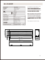
1
INSTALLATION AND
OPERATING INSTRUCTIONS FOR
WALL- MOUNT AND BUILT- IN UNITS
WM-BI-26-3623 WM-BI-26-3623-WHTGLS
WM-BI-34-4423 WM-BI-34-4423-WHTGLS
WM-BI-48-5823 WM-BI-48-5823-WHTGLS
WM-BI-72-8123 WM-BI-72-8123-WHTGLS
BI-50-FLUSHMT-BLKGLS BI-50-FLUSHMT-WHTGLS
BI-50-DEEP
BI-72-DEEP
WM-BI-2428-VLR
09 13-01
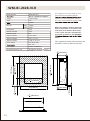
TABLE OF CONTENTS
CONGRATULATIONS!
In selecting this Amantii Wall Mount OR Built-in electric fireplace, you have chosen the
finest and most dependable fireplace on the market today. A beautiful and functional
addition to the finest homes. Welcome to the family of satisfied Amantii electric fireplace
owners.
Please read and carefully follow all of the instruction sfound in this manual. Please pay
special attention to the safety instructions provided in this manual. The instructions
included here will as sure that you have many years of dependable and enjoyable service
from your Amantii product.
Important instructions
Page 4
WM-BI-26-3623-/WHTGLS
Page 5
WM-BI-34-4423-/WHTGLS
Page 6
WM-BI-48-5823-/WHTGLS
Page 7
WM-BI-72-8123-/WHTGLS
Page 8
BI-50-FLUSHMT-BLKGLS/WHTGLS
Page 9
BI-50-DEEP
Page 10
BI-72-DEEP
Page 11
WM-BI-2428-VLR
Page 12
Installation Overview
Page 13
Package Contents
Page 14
Built-In Installation
Page 17
Wall Mount Installation
Page 22
Media options
Page 23
Fire Glass Media Installation
Page 24
Front Installation
Page 25
Operating the Unit
Page 26
Replacing The Remote Control Battery
Page 31
Care And Maintenance
Page 32
Fireplace Maintenance
Page 33
Trouble Shooting
Page 34
Service History
Page 35
Warranty
Page 36
Dealer Contact Information
Back Page
3
IMPORTANT INSTRUCTIONS
WARNING!
5. Do not use outdoors.
15.
ded
Cover Of Grounded
Outlet Box
Metal
Screws
Grounding Pin
A B
Adapter
C D
Grounding
Means
Grounding
Pin
Fig. 1
SAVE THESE INSTRUCTIONS
4
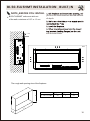
WM-BI-26-3623-/WHTGLS
WM-BI-26-3623 -/WHTGLS
Model Number
Built-In or Wall Mount Appliance
Voltage
120V AC,60Hz
Amps
12A
This appliance has been tested in accordance with the UL Standand 2021 for
appliances in the United States and Canada. If you need assistance during installa-
1500W
HEATER
HIGH
1500W
LOW
750W
NO HEATER
25W
MOTOR HEATER
19W
MOTOR FLAME
Appliance Width
4W
35 1/2” or 90.20 cm
Appliance Height
23” or 58.40 cm
Appliance Depth
6 3/4” or 17.30 cm
Gross Weight
55.68 lbs or 25.31kg
NOTE: This appliance must be electrically
wired and grounded in accordance with
local codes. In the absence oflocal codes,
us the current CSA C22.1 Canadian Electrical Code in Canada or the ANSI/NFPA
States.
Left side
74.81” or 190.00 cm
Rough Wall Opening Size
27”
55.9 cm
21 3/8
22” or 68.60 cm
10
23 1/2
35 1/2
6 3/4
1/4
23
Cord Length
26
5
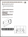
WM-BI-34-4423-/WHTGLS
Model Number
WM-BI-34-4423 -/WHTGLS
Voltage
120V AC,60Hz
Amps
12A
This appliance has been tested in accordance with the UL Standand 2021 for
Built-In or Wall Mount Appliance
appliances in the United States and Canada. If you need assistance during installa-
1500W
HEATER
HIGH
1500W
LOW
750W
NO HEATER
25W
MOTOR HEATER
19W
MOTOR FLAME
Appliance Width
4W
43 1/2” or 110.50 cm
Appliance Height
23” or 58.40 cm
Appliance Depth
6 3/4” or 17.30 cm
Gross Weight
65.78 lbs or 29.90kg
NOTE: This appliance must be electrically
wired and grounded in accordance with
local codes. In the absence oflocal codes,us the current CSA C22.1 Canadian Elec
trical Code in Canada or the ANSI/NFPA
States.
Left side
74.81” or 190.00 cm
Rough Wall Opening Size
35”
22“ or 88.9 cm
55.9 cm
21 3/8
10
23
Cord Length
43 1/2
34
6
6 3/4
1/4
31 1/2
WM-BI-48-5823-/WHTGLS
Model Number
WM-BI-48-5823 -/WHTGLS
Voltage
120V AC,60Hz
Amps
12A
Built-In or Wall Mount Appliance
This appliance has been tested in accordance with the UL Standand 2021 for
appliances in the United States and Canada. If you need assistance during installa-
1500W
HEATER
HIGH
1500W
LOW
750W
NO HEATER
25W
MOTOR HEATER
19W
MOTOR FLAME
Appliance Width
4W
57 1/2” or 146 cm
Appliance Height
23” or 58.40 cm
Appliance Depth
6 3/4” or 17.30 cm
Gross Weight
82.17 lbs or 37.35kg
NOTE: This appliance must be electrically
wired and grounded in accordance with
local codes. In the absence oflocal codes,
us the current CSA C22.1 Canadian Electrical Code in Canada or the ANSI/NFPA
States.
Left side
Cord Length
74.81” or 190.00 cm
Rough Wall Opening Size
49”
21 3/8
10
23
22“ or 124.46 cm 55.9 cm
57 1/2
6 3/4
1/4
45 1/2
48
7
WM-BI-72-8123-/WHTGLS
Model Number
WM-BI-72-8123 -/WHTGLS
Voltage
120V AC,60Hz
Amps
12A
This appliance has been tested in accordance with the UL Standand 2021 for
Built-In or Wall Mount Appliance
appliances in the United States and Canada. If you need assistance during installa-
1500W
HEATER
HIGH
1500W
LOW
750W
NO HEATER
25W
MOTOR HEATER
19W
MOTOR FLAME
Appliance Width
4W
81” or 205.7 cm
Appliance Height
23” or 58.40 cm
Appliance Depth
6 3/4” or 17.30 cm
Gross Weight
1331.21 lbs or 52.41kg
NOTE: This appliance must be electrically
wired and grounded in accordance with
local codes. In the absence oflocal codes,
us the current CSA C22.1 Canadian Electrical Code in Canada or the ANSI/NFPA
States.
Left side
74.81” or 190.00 cm
72 1/2”
22“ or 184 cm
23
10
Rough Wall Opening Size
55.9 cm
21 3/8
Cord Length
6 3/4
81
71 1/2
71
8
1/4
69
BI-50-FLUSHMT-BLKGLS/WHTGLS
Model Number
BI-50-FLUSHMT -BLKGLS/WHTGLS
Built-In or Wall Mount Appliance
Voltage
120V AC,60Hz
Amps
12A
This appliance has been tested in accordance with the UL Standand 2021 for
appliances in the United States and Canada. If you need assistance during installa-
1500W
HEATER
HIGH
1500W
LOW
750W
NOTE: This appliance must be electrically
wired and grounded in accordance with
local codes. In the absence oflocal codes,
us the current CSA C22.1 Canadian Electrical Code in Canada or the ANSI/NFPA
NO HEATER
25W
MOTOR HEATER
19W
MOTOR FLAME
Appliance Width
4W
51” or 129.6 cm
Appliance Height
23” or 58.40 cm
Appliance Depth
6 3/4” or 17.30 cm
Gross Weight
80lbs or 36.35kg
States.
Cord Length
74.81” or 190.00 cm
Rough Wall Opening Size
49” 22“ or 124.46 cm
55.9 cm
1/4
21 3/8
10
23
Left side
45 1/2
51
6 3/4
48
9
BI-50-DEEP
Model Number
BI-50-DEEP
Built-In Appliance
Voltage
120V AC,60Hz
Amps
12A
This appliance has been tested in accordance with the UL Standand 2021 for
appliances in the United States and Canada. If you need assistance during installa-
1500W
HEATER
HIGH
1500W
LOW
750W
NOTE: This appliance must be electrically
wired and grounded in accordance with
local codes. In the absence oflocal codes,
us the current CSA C22.1 Canadian Electrical Code in Canada or the ANSI/NFPA
NO HEATER
25W
MOTOR HEATER
19W
MOTOR FLAME
Appliance Width
48 5/8” or 123.5 cm
Appliance Height
23 5/8” or 60 cm
Appliance Depth
12 1/4” or 31.2 cm
Gross Weight
94.6lbs or 43kg
4W
States.
This appliance for built-in only.
Left side
50”
4" [99mm]
24“ or 127 cm 60 cm
12" [302mm]
1534" [402mm]
74.81” or 190.00 cm
Rough Wall Opening Size
2321" [600mm]
Cord Length
4541" [1149mm]
12" [302mm]
4821" [1235mm]
1234" [322mm]
4941" [1249mm]
10
BI-72-DEEP
Model Number
BI-50-DEEP
Built-In Appliance
Voltage
120V AC,60Hz
Amps
12A
This appliance has been tested in accordance with the UL Standand 2021 for
appliances in the United States and Canada. If you need assistance during installa-
1500W
HEATER
HIGH
1500W
LOW
750W
NOTE: This appliance must be electrically
wired and grounded in accordance with
local codes. In the absence oflocal codes,
us the current CSA C22.1 Canadian Electrical Code in Canada or the ANSI/NFPA
NO HEATER
25W
MOTOR HEATER
19W
MOTOR FLAME
Appliance Width
72 1/8” or 183.2 cm
Appliance Height
23 5/8” or 60 cm
Appliance Depth
12 1/4” or 31.2 cm
Gross Weight
126.5lbs or 57.5kg
4W
States.
This appliance for built-in only.
Left side
73”
4" [99mm]
24“ or 185.5 cm 60 cm
12" [302mm]
1534" [402mm]
74.81” or 190.00 cm
Rough Wall Opening Size
2312" [600mm]
Cord Length
6834" [1746mm]
7214" [1832mm]
7234" [1846mm]
12" [302mm]
1234" [322mm]
11
WM-BI-2428-VLR
Model Number
WM-BI-2428-VLR
Voltage
120V AC,60Hz
Amps
12A
This appliance has been tested in accordance with the UL Standand 2021 for
Built-In or Wall Mount Appliance
appliances in the United States and Canada. If you need assistance during installa-
1500W
HEATER
HIGH
1500W
LOW
750W
NO HEATER
25W
MOTOR HEATER
15W
MOTOR FLAME
Appliance Width
4W
24” or 61cm
Appliance Height
28” or 71.1 cm
Appliance Depth
9 1/8” or 23.1 cm
Gross Weight
57.2 lbs or 26kg
NOTE: This appliance must be electrically
wired and grounded in accordance with
local codes. In the absence oflocal codes,
us the current CSA C22.1 Canadian Electrical Code in Canada or the ANSI/NFPA
States.
This appliance can be wall mount on the
flat wall or coner or built-in the wall.
Left side
Cord Length
74.81” or 190.00 cm
Rough Wall Opening Size
20 ” 26“ or 50.8 cm
66 cm
243
4" [628.4mm]
145" [371mm]
8
28" [711mm]
81" [205.5mm]
8
12
24" [610mm]
177" [452.6mm]
8
91" [231.3mm]
8
1" [25.4mm]
63
4" [170mm]
1" [410mm]
168
INSTALLATION OVERVIEW
NOTE: BEFORE YOU INSTALL
SITE SELECTION
wall.
Review and consider all of the following condir
r
wo (2) wall
-
overhead light-
et for ease of electric
and all hardware fr
ox and r ove all
aterials prior to installapackaging relat
Power supply Wire Gage
Voltage
Wire Gage
Fuse
14 G .
ht and away fr
electric
t-In (page 17)
W
nt (Page 22)
120 v
re etc.
dir
ing.
ethods:
rapes, pillow
15 MP
Wall switch / t hermostat Wire Gage
Voltage
Wire Gage
5 Volts
18 Gage
Volt cir
referr
cated cir
r
red.
-
PACKAGING LIST
with:
WARNING:
re the power cord is not installed
i
so
that it is pinched or against a sharp edge
and ensure that the power cord is stored
or
red to avoid tripping or snagging
ry to persons.
st c
with local
codes
-
ry to persons.
To reduce the risk of fire, do not store or
use gasoline or other flammable vapors
and liquids in the vicinity of the heater.
r
te control
Decorative media (See page 23)
TOOLS & BUILDING SUPPLIES
NORMALLY REQUIRED
T
Phillip
aw and/
Level
rewdriver
aw
Tape
E
Fr
aterials
Wall Finishing Marterials
aterials
stable)
Pliers
re
Gloves
13
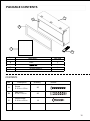
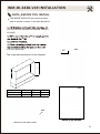
PACKAGE CONTENTS
B
C
A
E
D
Part
A
B
C
D
E
Glass
1
1
1
1
1
Wall Bracket
Decorative Media
CONTENTS
Part
14
Description
Quantity
A
Screw
0.16 in. x 1.0 in.
20
B
Wall Plug
0.3 in. x 1.5 in.
20
C
Wood Screw
0.16 in. x 0.6 in.
18
Picture
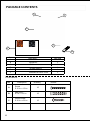
PACKAGE CONTENTS
C
B
A
E
D
Part
A
B
C
D
E
1
1
1
1
1
Trim
Glass
Decorative Media
CONTENTS
Part
Description
Quantity
A
Screw
0.16 in. x 1.0 in.
20
B
Wall Plug
0.3 in. x 1.5 in.
20
C
Wood Screw
0.16 in. x 0.6 in.
18
Picture
15
PACKAGE CONTENTS
B
C
A
F
E
D
Part
A
B
C
D
E
F
1
1
1
1
1
1
Glass
Appliance
Wall bracket
Fire Glass Media
Brackets for Valor Front
CONTENTS
Part
16
Description
Quantity
A
Screw
0.16 in. x 1.0 in.
10
B
Wall Plug
0.3 in. x 1.5 in.
10
C
Wood Screw
0.16 in. x 0.6 in.
10
Picture
NEW CONSTRUCTION OR
RENOVATION
Two people may be needed to
min. 5 cm
2 in
moisture and is located at least 0.91 m or
als such as curtains or drapes, furniture,
bedding, paper, etc.
WALL
CAUTION:
Sides ---------------------- 2 in / 5 cm
Floor ---------------------- 13 3/4 in / 35 cm
Top ---------------------- 2 in / 5 cm
Back ---------------------- 0 in / 0 cm
2. Place the appliance in selected loca-
min. 5 cm
2 in
FLOOR
min. 35 cm
13 3/4 in
and store appliance in a safe, dry and
4. Prepare a wall with a framed opening to accomodate the size of your unit.
Leave at least 1/4” (6mm) around the
edge of the appliance. Any new wiring
must be done in compliance with local
and national codes and other applicable
WARNING:
To prevent contact with sagging or
ance must not be installed against
WARNING:
outlets or circuits. To reduce the risk
licensed electrician.
result.
17
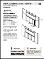
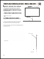
FIREPLACE INSTALLATION BUILT IN
NOTE BEFORE YOU INSTALL
Units (models listed in table below) must
stick out of the wall a minimum of
just the unit to achieve the desired amount
of depth.
k
2 1/4" or 5.8 cm
r
w
ow
and the wall studs.
214" [58mm]
Wall
H
The rough wall opening size of the fireplace.
W
D
18
WM-BI-26-3623
WM-BI-34-4423
WM-BI-48-5823
WM-BI-72-8123
W(")
D(")
27
5
35
5
49
5
72 1/2
5
H(")
22
22
22
22
BI-50-FLUSHMT INSTALLATION BUILT IN
NOTE BEFORE YOU INSTALL
BI-50-FLUSHMT units must stick out
of the wall a minimum of 1/2" or 1.3 cm.
just the unit to achieve the desired amount
of depth.
k
r
ow
w
and the wall studs.
1" [13mm]
2
Wall
H
The rough wall opening size of the fireplace.
W(")
BI-50-FLUSHMT
49
D(")
5
H(")
22
W
D
19
BI-50/72-DEEP INSTALLATION- BUILT IN
NOTE BEFORE YOU INSTALL
The BI-50-DEEP and BI-72-DEEP can be
flush mounted to the wall allowing finishing
materials to be built right down to the glass
trim.
just the unit to achieve the desired amount
of depth.
k
r
ow
w
and the wall studs.
H
The rough wall opening size of the fireplace.
W
D
BI-50-DEEP
BI-72-DEEP
20
W(")
50
73
D(")
13
13
H(")
24
24
WM-BI-2428-VLR INSTALLATION
NOTE BEFORE YOU INSTALL
The WM-BI-2428-VLR can mount on a flat
wall or across a corner. It can also be built-in.
just the unit to achieve the desired amount
of depth.
k
r
ow
w
and the wall studs.
3/4"
20mm
H
The rough wall opening size of the fireplace.
wall
W
D
wall
WM-BI-2428-VLR
W(")
20
D(")
9
H(")
26
wall
Mount on the wall corner.
Mount on the flat wall.
21
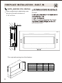
NOTE: BEFORE YOU INSTALL
It is strongly recommended that the screws be
screwed into the wall studs where possible. If
Stakes for hanging
wall bracket
anchors are used.
ke sure it is level.
13 3/4 inch
hanging into the keyholes on the back of the unit.
Floor
3. Check the appliance for stability ensuring that
the appliance will not pull free from the wall.
4. Drive mounting screws into the mounting bracket on
the bottom of unit.
Stakes for hanging
Wall
Back of unit
Side view
22
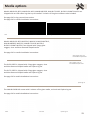
Media op ons
Models WB-BI-26-3623, WM-BI-34-4423, WM-BI-48-5823, WM-BI-72-8123, BI-50-FLUSHMT-BLKGLS are
shipped with an LED ember log that is pre-installed. 3 colours of fire glass media are also included.
See page 24 for log removal instruc ons.
See page 24 for media installa on instruc ons.
Clear
Harvest Moon
LED log
Sun Tea
Models WB-BI-26-3623-WHTGLS, WM-BI-34-4423-WHTGLS,
WM-BI-48-5823-WHTGLS, WM-BI-72-8123-WHTGLS,
BI-50-FLUSHMT-WHTGLS are shipped with 3 large glass
nuggets, clear and blue diamond shaped media.
See page 24 for media installa on instruc ons.
Glass nuggets, clear and
blue diamond shaped media
Glass nuggets, clear and
blue diamond shaped media
The BI-50-DEEP is shipped with 3 large glass nuggets, clear
and blue diamond shaped media and 6 piece log set.
The BI-72-DEEP is shipped with 6 large glass nuggets, clear
and blue diamond shaped media and 6 piece log set.
See page 24 for media installa on instruc ons.
6 piece log set
The WM-BI-2428-VLR comes with 2 colours of fire glass media, real coal and 6 piece log set.
See page 24 for media installa on instruc ons.
Sable
Black
Real coal
6 piece log set
23
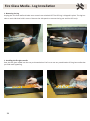
Fire Glass Media - Log Installa on
1. Removing the log
Unplug the unit from wall and make sure controls are switched off. The LED log is shipped in place. The log has
tabs on each side that hold it secure. Remove the side panel to remove the log set and the LED strip.
1. Installing the fire glass media
Pour the fire glass media into the tray as shown below. Fee free to use any combina on of fire glass media that
you find most appealing.
24
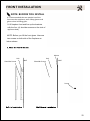
FRONT INSTALLATION
NOTE: BEFORE YOU INSTALL
It is recommended that two people install the
front onto the appliance, wear safety glasses and
gloves when handling glass.
1.Lift fireplace front and line up the brackets
with the four (4) shoulder screws on the side of
appliance body
NOTE: Before you lift the front glass. Unscrew
two screws on both side of the fireplace as
below shown.
Mount
Unit
Shoulder Screw
Wall
Unit
Shoulder Screw
Wall
Screw
25
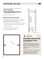
OPERATING THE UNIT
1. Make sure the appliance is switched OFF (refer
30
Wall
on the right hand side of the unit.
3. Plug unit into electrical outlet.
HARD-WIRE INSTALLATION
If it is necessary to hard wire this appliance, a qualified
electrician may remove the cord connection, and wire the
appliance directly to the house hold wiring.
1. Unscrew two screw show in the below. Remove the cover
plate and the power cord fix piece, remove power cord.
Remove the knockout.
2. Attach the wiring to the junction block
3. Put the plate back and screw back.
Power adaptor port
WARNING:
outlets or circuits. To reduce the risk of
licensed electrician.
Fix plate
Appliance has overheated and safety
device has cause the thermal switch to
discount. Unplug the appliance, allow
appliance to cool for 15 minutes, then
plug back in.
Inspect for an objects on or adjacent to
the heater that may have locked the
airflow or otherwise caused high
temperatures to have occurred.
26
OPERATING THE UNIT
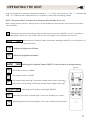
Plug the fireplace in and turn the power switch to “ I “ to turn the power on. The “ I ” indicates ON
and “ O ” indicates OFF. When the unit is turned on, there will be chiming sound.
NOTE: The power switch is located at the bottom left hand side of the unit.
When using remote control, always point it at the middle of the fireplace, and keep not far away
than 6 metres.
The button located at the top position of the remote control is ON/OFF. Press it, the flame
and ember will be on. The heater will be off. Press again, the fireplace will turn off.
Switching the fireplace flame and ember bed light ON/OFF. It has functions of
setting memory.
Adjust the brightness of flame.
Adjust the brightness of ember.
Switching the fireplace heater ON/OFF. It has functions of setting memory.
Figure 19
The heater works at 1500W.
The heater works at 750W.
The heater keep working if the room temperature lower than 22
.
The heater not working if the room temperature higher than 25 .
Switching the fireplace mood light ON/OFF.
Switching the color of mood light. There are 16 different colors.
Switching flash kind of mood light. There are 4 different flash styles.
27
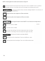
NOTE: All white glass front model use the remote as Figure 20.
The button located at the top position of the remote control is ON/OFF. Press it, the flame
and ember will be on. The heater will be off. Press again, the fireplace will turn off.
Switching the fireplace flame and ember bed light ON/OFF. It has functions of
setting memory.
Adjust the blue colour brightness of flame and ember.
Adjust the yellow colour brightness of flame and ember.
Switching the fireplace heater ON/OFF. It has functions of setting memory.
Figure 20
The heater works at 1500W.
The heater works at 750W.
The heater keep working if the room temperature lower than 22
.
The heater not working if the room temperature higher than 25 .
Switching the fireplace mood light ON/OFF.
Switching the color of mood light. There are 16 different colors.
Switching flash kind of mood light. There are 4 different flash styles.
28
ReMoTe coNTRol opeRATIoN
1. For remote to function make sure the heater is plugged-in
and mains power switch located on the bottom right hand
side is at position I.
2. When operating the remote make sure you point the
remote to the centre of the heater unit and make sure
each time you press the button the LED indicator located
on top right hand corner of the remote blinks. The buzzer
inside the unit will beep once; if the LED fails to blink
check the batteries. It takes some time for the receiver
to respond to the transmitter. Do not PRESS the buttons
more than once within two seconds for correct operation
3. Power On “
“ button: The power-on button at top left
corner of the remote is the mains ON/OFF power button.
This will turn off all the functions and the heater will be in
standby mode.
4. Flame Power On button
: This button controls both
the amber and blue colour flame. Press this button once
to turn ON the flame effect. Once the flame effect is ON
use the + and – buttons as explained below to adjust the
flame brightness as desired. Press this button again to
turn OFF the flame effect.
• The Red +5 or -5 buttons control the
brightness of the ] Amber fame.
To increase the brightness / flame height,
press and release the +5 button.
Each time you press this button the brightness
will increase by a small amount, until the
maximum is reached.
To decrease the brightness / flame height,
press and release the -5 button.
Each time you press this button the brightness
will decrease by small amount, until the
minimum brightness is reached.
The blue
+5 or -5 buttons control the
brightness of the Blue fame.
To increase the brightness / flame height,
press and release the +5 button.
Each time you press this button the
brightness will increase by a small amount,
until the maximum is reached.
To decrease the brightness / flame height,
press and release the -5 button.
Each time you press this button the brightness
will decrease by small amount, until the
minimum brightness is reached.
You can mix the amber and the blue flame to
create a realistic flame effect.
5. heATeR
button: This button is the
heater ON/OFF button. Press this button to
turn the heater ON. The heater will always
start at high heat setting 2000W. To turn OFF
the heater press this button again.
hIGh button: Press the high button to switch
the heater to high heat setting 2000W.
loW button: Press the high button to switch
the heater to LOW heat setting 1000W.
RooM TeMp button: Press the high button to
switch the heater to AUTO mode. Under this
mode the heater will operate in similar way as
explained above for the manual operation.
6. To turn OFF the heater unit completely press
the “
“ button once.
Realistic flame effect:
The flame effect is controlled by LEDs; the
LEDs are non-replaceable type but have been
manufactured to last for long life.
29
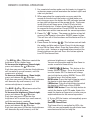
1. Power ON/OFF switch
2. Heat control button
3. Flame control button
4. HEATER LED
5. POWER LED
Plug the heater into a suitable outlet.
1) “Power ON/OFF”
Set this switch to position I to turn the product ON. Setting it to O to turn the product OFF.
POWER LED will be lit when the fireplace insert is on.
The
2) “Heat control button”
Press the HEAT button repeatedly to set the heater to the desired heat setting. The HEATER LED will
indicate the current setting for the heater as shown below:
HEATER LED = Red = 1500W HEAT OUTPUT
HEATER LED = Blue = 750W HEAT OUTPUT
HEATER LED = Purple = AUTO MODE
HIGH / 1500W
LOW / 750W
AUTO MODE
HEATER INDICATOR
HEATER INDICATOR
HEATER INDICATOR
OFF
Auto Mode
In this mode the heater will automatically turn on and off. When the room temperature drops below
71° F. (22° C) the heater will turn on to the high heat setting (1500 watt). When the room temperature
is between 71° and 77° F (22-25° C) the heater output will switch to low heat setting (750W). When
the room temperature goes above 77° F (25° C) the heater will turn off.
3) “Flame control button”
Press the Flame brightness adjustment button to adjust the flame height and ember bed brightness.
Press the FLAME control button to cycle through LO, MED, HI and OFF.
30
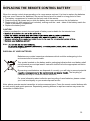
REPLACING THE REMOTE CONTROL BATTERY
When the remote control stops operating or its range seems reduced, it is time to replace the batteries
with new ones. Remove the batteries if the remote control won’t be used for a long period of time.
1. The battery compartment is located on the back end of the remote.
2. Press the small tab inward as you slide the battery door open and remove the old batteries.
3. Replace with (2) AAA batteries (not included), making sure the + and - sides of the battery match the
inside of the battery compartment.
4. Replace the battery door.
CAUTION:
Always purchase the correct size and grade of battery most suitable for the intended use.
y.
Note:
Caution for Ingestion.
DISPOSAL OF USED BATTERIES
Batteries may contain hazardous substances which could be endangering to the
enviroment and to human health.
This symbol marked on the battery and/or packaging indicates that used battery shall
not be treated as municipal waste. Instead it shall be left at the appropriate collection
point for recycling.
By ensuring used batteries are disposed of correctly, you will help to prevent potential
The recycling of
materials will help to conserve natural resources.
For more information about collection and recycling of used batteries, please contact
your local municipality or your waste disposal service.
Note: please operate remote transmitter at a slow measured pace. Press the remote control buttons with
an even motion and gentle pressure. Repeatedly pressing buttons in rapid succession may cause the
transmitter to Malfunction.
31
CARE AND MAINTENANCE
CLEARANCE TO COMBUSTIBLES
Keep electrical cords, drapery, furniture and other combustibles at least 3 ft. from the front of the heater
and away from the sides.
CLEANING TRIM
Clean the metal trim using a soft cloth, slightly dampened with a citrus oil-based product and buff with a
clean soft cloth. Do not use brass polish or household cleaners as these products will damage the metal
trim. Citrus oil-based products can be obtained at supermarkets or hardware stores.
WARNING: Make sure the power is turned off before proceeding. Any electrical repairs
or rewiring of this unit should be carried out by a licensed electrician in accordance with
national and local codes.
If repairing or replacing any electrical component or wiring, the original wire routing,
color coding and securing locations must be followed.
WARNING: Electrical outlet wiring must comply with local building codes and other
WARNING:
. Immediately
electrical system.
WARNING: Disconnect power before attempting any maintenance or cleaning to reduce
WARNING: During any service of this appliance, the power to the unit must be turned off.
First turn the main power switch to the OFF position. Then remove the electrical plug from
the wall outlet.
32
FIREPLACE MAINTENANCE
WARNING:
Disconnect power before performing any maintenance or cleaning to reduce the risk of
LED LIGHT BULB REPLACEMENT
LED light bulbs are to be replaced by the manufacturer, it’s service agent or similar quali-
WARNING:
UNIT DISPOSAL
Do not dispose with other household wastes. To prevent possible harm to the environment
or human health from uncontrolled waste disposal, recycle it responsibly to promote the
33
TROUBLE SHOOTING
WARNING
Disconnect power before performing any maintenance and allow to cool before servic-
SYMPTOM
POSSIBLE CAUSES
Fireplace doesn’t work.
Fireplace inner temperature over
heatng or home circuit breaker
has opened.
or log set and ember is not
glowing.
LED Light(s) burt out or wiring is
loose.
Remote Control does not
work.
CORRECTIVE ACTION
Reset switch by turning main power switch off and waiting five
mimutes, then turning it back on.
if necessary. Inspect light bulbs and replace if necessary.
Replace AA batteries in remote control. If problem persists,
there may have been a loss of power to the unit as a possible result from a power failure
(i.E. Breaker tripped).
Circuit Breaker trips or fuse
blows when the unit is on.
to ensure it is on a dedicated circuit with proper amp. rator replace wiring and/or connectors as necessary.
Heater does not provide heat Thermal switch has been trippped. Turn the unit off and unplug the unit for five minutes.
when turned on
Circuit breaker has been tripped
Plug back in and turn the unit on. If plug can be reached,
follow directions for tripped circuit breaker. Turn off circuit
breaker that supplies electricity to the unit. Wait five minutes
then flip circuit breaker back on.
not turn on.
Appliance will not come on
ON.
34
a. Appliance has overheated and
mal switch to disconnect.
OR
b. House circuit breaker has
tripped.
a. Unplug the appliance, allow appliance to cool for 15 minutes, then plug back in.
a. Appliance is not plugged into
an eletrical outlet.
OR
b. Appliance has overheated and
mal switch to disconnect.
a. Check plug and plug it in.
b. Reset the house circuit breaker
b. Unplug the appliance, allow appliance to cool for 15 minutes, then plug back in.
SERVICE HISTORY
This heater must be serviced annually depending on usage.
Date
Dealer
Name
service technician
Name
service Performed
special Concerns
NOTES:
35
WARRANTY
Amantii Imports Corp. (”Amantii”) warrants that your newly purchased Amantii electric fireplace is free from manufacturing and
material defects for a period of one (1) year from the date of the first purchase, subject to the conditions and limitations contained
below.
Warranty Application & Exclusions
This limited warranty applies to your newly purchased Amantii electric fireplace; the limited warranty’s application is limited to purchases made in any province of Canada or in any of the 52 States of the United States of America, including the District of Columbia.
Only the original purchaser of the product is eligible for coverage under this limited warranty; the warranty is not transferable.
Products excluded from this limited warranty
Light bulbs are not covered by this limited warranty and are the sole responsibility of the owner/purchaser.
Warranty Coverage and Team
Products covered by this limited warranty have been tested and inspected prior to shipment and, subject to the provisions of this warranty, Amantii warrants such products to be free from defects in material and workmanship for a period of one (1) year from the date
of the first purchase of such products.
The limited one (1) year warranty period for products also applies to any implied warranties that may exist under applicable law. Some
jurisdictions do not allow limitations on how long an implied warranty lasts, so the above limitation may not apply to the purchaser.
All other warranties - expressed or implied - with respect to the product, its components and accessories or any obligation/liabilities
on the part of Amantii are hereby expressly excluded.
Limitations to Coverage Under Limited Warranty
This limited warranty does not apply to products that have been repaired, except by Amantii or its authorized service representatives,
or otherwise altered. This limited warranty further does not apply to defects resulting from misuse, abuse, accident, neglect, incorrect
installation, improper maintenance or handling, or operation with an incorrect power source.
Products made by other manufacturers, sold with the product or thereafter, are not covered by this limited warranty. The use of unauthorized components will render this warranty null and void.
Service Under Limited Warranty
Defects must be brought to the attention of Amantii Technical Service by contacting Amantii at (1-888-406-8764), or at # 1503-7088
18th Avenue, Burnaby, British Columbia, Canada, V3N 0A2. Please have your proof of purchase, catalogue/model and serial numbers
available when calling; any and all service under the limited warranty requires a proof of purchase of the product.
Defects
Should a product or part covered by this limited warranty be proven to be defective, in material or workmanship, and during the one
(1) year limited warranty period, Amantii will replace such defective product or part without charge. If Amantii is unable to replace
such product, or if replacement is not commerically practicable or cannot be timely done, in its sole discretion Amantii may, in lieu of
replacement, choose to refund the purchase price for such product or part.
Limitations
In no event will Amantii, including without limitation any of its directors, officers, shareholders, employees, consultants, agents, heirs,
executors, administrators and assigns, be liable to the purchaser or any third party, whether in contract, in tort, or on any other basis
for any indirect, special, punitive, exemplary, consequential, or incidental loss, cost or damage arising out of or in connection with the
sale, maintenance, use or inability to use the product, even if Amantii, including without limitation any of its directors, officers,
shareholders, employees, consultants, agents, heirs, executors, administrators and assigns, have been advised of the possibility of
such losses, costs or damages, or if such losses, costs or damages are foreseeable. In no event will Amantii, including without limitation any of its directors, officers, shareholders, employees, consultants, agents, heirs, executors, administrators and assigns, be liable
for any direct losses, costs or damages that exceed the purchase price of the product.
Some jurisdictions do not allow the exclusion or limitation of incidental or consequential damages, so the above limitation or exclusion
may not apply to the purchaser.
Application of Provincial and State law
This limited warranty gives you specific legal rights, and you may also have other rights which vary from jurisdiction to jurisdiction. The
provisions of the United Nations Convention on Contracts for the Sale of Goods shall not apply to this limited warranty or the sale of
products covered by this limited warranty.
General
Amantii reserves the right to make changes at any time without notice, in design, material, specifications, prices and the right to discontinue styles and products.
36
ELECTRIC FIREPLACES