1
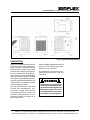
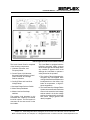
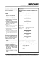
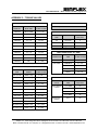
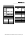
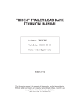
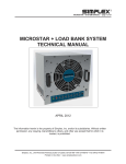
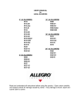
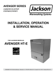
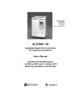
LOAD BANK
TECHNICAL MANUAL
(LBD Series)
Customer: XXXXX
Work Order: XXXXX-XX-XX
Model: Merlin 150KW-300KW
March 2011
The information herein is the property of Simplex, Inc. and/or its subsidiaries.
Without written permission, any copying, transmitting to others, and other use
except that for which it is loaned, is prohibited.
(File: Merlin-150-300c.indd)
LOAD BANK MANUAL • Merlin 150-300 Load Bank • page 1 of 15
Contents
DESCRIPTION .............................................................................. 2
PRIMARY INSPECTION ............................................................... 4
LOAD BANK LOCATION.............................................................. 4
OPERATION.................................................................................. 5
Shutdown ................................................................................ 6
COOLING FAILURE SUBSYSTEM .............................................. 6
LOAD OVER VOLTAGE DETECTION SUBSYSTEM .................. 7
LOAD ELEMENTS ........................................................................ 7
MAINTENANCE ............................................................................ 8
Each Operation ...................................................................... 8
Every 50 Hours or 6 Months ................................................. 8
TROUBLESHOOTING .................................................................. 8
Cooling Fan Motor Will Not Operate .................................... 8
Load Over Voltage Indicated ................................................ 9
Cooling Failure Indicated ...................................................... 9
Test Meters Do Not Operate Properly .................................. 9
Some Load Steps Cannot Be Energized .............................. 9
DRAWINGS AND PARTS LIST .................................................... 9
APPENDIX A - ABBREVIATIONS USED IN THIS MANUAL..... 10
APPENDIX B - CALCULATIONS & FORMULAS ...................... 11
APPENDIX C - TORQUE VALUES ............................................. 14
Simplex, Inc., 5300 Rising Moon Road, Springfield, IL 62711-6228 • 217-483-1600 • Fax 217-483-1616
Merlin-150-300c.indd • © 2011 Simplex, Inc. All Rights Reserved. • Printed in the USA. • www.simplexdirect.com
LOAD BANK MANUAL • Merlin 150-300 Load Bank • page 2 of 15
Part of Typical Pictorial Drawing
DESCRIPTION
Simplex Load Banks are precision test
instruments specifically designed to
apply a discrete, selectable resistive
electrical load to a power source while
measuring the response of the generator to the applied load. They also provide a means for routine maintenance
exercise to assure long term reliability
and readiness of the standby generator.
Exercise Load Banks eliminate the detrimental effects of unloaded operation
of diesel engine generators.
This fully self-contained Load Bank
includes test instrumentation, cooling system, rugged load elements,
load-application control devices and
automatic system protection devices.
Operating controls are located on a
Local Control Panel.
See the Load Bank Specifications Sheet
in the front of this manual for the specifications of your Load Bank.
The illustrations in this manual are examples only and may differ from your
Load Bank.
Always remove all power from
the load bus and all fan/control
power before servicing the Load
Bank. Never operate or service
a Load Bank that is not properly
connected to an earthground.
Simplex, Inc., 5300 Rising Moon Road, Springfield, IL 62711-6228 • 217-483-1600 • Fax 217-483-1616
Merlin-150-300c.indd • © 2011 Simplex, Inc. All Rights Reserved. • Printed in the USA. • www.simplexdirect.com
LOAD BANK MANUAL • Merlin 150-300 Load Bank • page 3 of 15
Part of Typical Local Control Detail Drawing
The Local Control Panel is comprised
of the following components:
1. Voltmeter, Ammeter, and
Frequency Meter
2. Control Power, Volt-Ammeter,
Ammeter Range Selector, Control
Power Selector, and Voltage
Selector switches
3. Cooling Failure and Load Over
Voltage lamps
4. Ammeter Range Selector Switch
5. Alarm Reset pushbutton
6. Master Load and load step
switches
The resistive load elements in this
Load Bank are cooled by a horizontal
forced air system. The load system is
connected to the test source via the
load cables.
This Load Bank is equipped with the
following automatic safety systems
which de-energize all load steps when
any condition is present which could
damage the Load Bank or present a
safety hazard to the operator:
1. The Cooling Failure Subsystem deenergizes any load applied when
cooling of the load elements becomes
inadequate due to fan failure, high
intake air temperature, or high exhaust temperature.
2. The Load Power Over Voltage Failure
System removes all load from the test
source in the event the Load voltage
selector switch is in the low voltage
position (less than 240V), and a high
test source voltage (greater than
480V) is applied.
Simplex, Inc., 5300 Rising Moon Road, Springfield, IL 62711-6228 • 217-483-1600 • Fax 217-483-1616
Merlin-150-300c.indd • © 2011 Simplex, Inc. All Rights Reserved. • Printed in the USA. • www.simplexdirect.com
LOAD BANK MANUAL • Merlin 150-300 Load Bank • page 4 of 15
PRIMARY INSPECTION
Preventative visual inspections of the
shipping crate and Load Bank is advised. Physical or electrical problems
due to handling and vibration may occur. Never apply power to a Load Bank
before performing this procedure. The
following Nine Point/30 Minute Inspection is recommended before installation, as part of the 50 hour / 6 month
maintenance schedule and whenever
a Load Bank is relocated:
1. If crate shows any signs of damage
examine the Load Bank in the corresponding areas for signs of initial
problems.
2. Check the entire outside of the
cabinet for any visual damage which
could cause internal electrical or
mechanical problems due to reduced
clearance.
3. Operate all hinged panels and doors
for smooth and safe operation, try all
latches and knobs.
4. Rotate and push all switches through
all positions to ensure smooth operation.
5. Check cooling system by inspecting
fan motor and blade. Slowly rotate
blade by hand and note clearance
of blade tip through its rotation near
the housing. Observe free rotation
of motor shaft.
6. Inspect all relays, timers, and control
modules by opening all accessible
panels. Make sure all components
are secure in their bases and safety
bails are in place. Spot check electrical connections for tightness. If any
loose connections are found inspect
and tighten all remaining connections.
If any problems are observed
during Primary Inspection call
the Simplex Service Manager at
217-483-1600 (24hrs.)
7. Examine all accessible internal
electrical components such as fuses,
contactors and transformers. Check
lugged wires at these components.
8. Inspect bottom of crate/enclosure
for any components that may have
jarred loose during shipment such as
indicator light lenses, switch knobs,
etc.
9. Visually inspect element chamber
for foreign objects, broken ceramic
insulators, mechanical damage.
LOAD BANK LOCATION
The load elements in this Load Bank
are cooled by a horizontal forced air
system which discharges through the
rear of the cabinet. Location of the Load
Bank is of prime importance and should
be done by trained personnel. It is one
of the most critical factors involved in
safe operation. The Load Bank must
be positioned and installed according
to large airflow requirements. Never
point the exhaust at a nearby surface or
object which may be adversely affected
by high temperature. Never operate the
Load Bank in a confined space without
regard for adequate intake of air and
provision for exit of high temperature
exhaust. Consider that the Load Bank
and a nearby generator set may have to
compete for cooling air. Never bounce
hot exhaust air off nearby objects and
allow it to recirculate through the cooling
system. Never operate the Load Bank
in proximity to a sprinkler system.
Simplex, Inc., 5300 Rising Moon Road, Springfield, IL 62711-6228 • 217-483-1600 • Fax 217-483-1616
Merlin-150-300c.indd • © 2011 Simplex, Inc. All Rights Reserved. • Printed in the USA. • www.simplexdirect.com
LOAD BANK MANUAL • Merlin 150-300 Load Bank • page 5 of 15
OPERATION
1. Confirm the test source
is properly grounded and
ground the Load Bank to its
own independent ground.
2. Confirm the “Control Power”
circuit breaker (FCB) is in the
“Off” position.
3. See Control Section Drawing:
a. Using the cables provided,
connect the load source to
the Load Bank as shown.
b. If external control power
is desired, place the External Fan Control Power
Plug into a 120V, 1ø,
60Hz, 15A receptacle.
4. Place the “Control Power
Selector” switch and “Voltage Selector” switch in the
appropriate positions.
5. Start-up generator set or bring other
test source on line.
If External Control Power is being
used, place the “Control Power” circuit breaker to energize the cooling
fan before starting the generator to
assure proper fan operation (Step
7).
6. Adjust power source voltage and
frequency.
7. Place the “Control Power” circuit
breaker (FCB) in the “On” position
to energize the cooling fan.
A false “Cooling Failure” lamp indication will be present until the cooling
fan creates sufficient airflow to close
the Fan Pressure Switch (PS) and
the “Alarm Reset” pushbutton is
pressed (Step 9).
8. Visually observe correct fan operation and investigate any unusual fan
related noises.
Part of Typical Control Section Drawing
9. Check air intake for obstructions
and confirm positive air flow.
10. Press the “Alarm Reset” pushbutton.
11. Verify the “Cooling Failure” lamp is
extinguished before proceeding.
When the “Cooling Failure” lamp
extinguishes, control power is supplied to the “Master Load” switch.
12. Select the desired load steps by
placing them in the “On” position.
13. Place the “Master Load” switch in
the “On” position.
This simultaneously applies all of
the load steps which are in the “On”
position.
Trim is achieved by flipping the
load steps “On” and “Off” while the
“Master Load” is in the “On” position.
14. Adjust source voltage and load.
Monitor as needed.
Simplex, Inc., 5300 Rising Moon Road, Springfield, IL 62711-6228 • 217-483-1600 • Fax 217-483-1616
Merlin-150-300c.indd • © 2011 Simplex, Inc. All Rights Reserved. • Printed in the USA. • www.simplexdirect.com
LOAD BANK MANUAL • Merlin 150-300 Load Bank • page 6 of 15
SHUTDOWN
1. De-energize the load.
2. Run the cooling fan for 5
minutes to assure a thorough cool down of all load
elements (optional).
3. Place the “Control Power”
circuit breaker (FCB) in the
“Off” position.
COOLING FAILURE
SUBSYSTEM
Excessive intake or exhaust
temperatures or any reduction in cooling air flow for any
reason is indicated by the
illumination of the “Cooling
Failure” lamp. All load steps
are locked out until the problem is corrected and failure
related relays are reset. The
Cooling Failure Subsystem consists of
the Alarm Reset pushbutton (PB1), Fan
Pressure Switch (PS), the Intake Temperature Switch (INTS), the Exhaust
Temperature Switch (EXTS), and the
Cooling Failure Relay (CFR). The CFR
must be energized to enable load application. When the cooling fan creates
sufficient airflow the PS closes. The
operator presses the PB1 to complete
If a failure occurs during Load
Bank operation, the Load Bank
will de-energize all load steps.
The operator must reset the
Load Bank by turning it “Off”
then “On”. The load failure
must be investigated and corrected before load application
can resume.
Part of Typical Control Section Drawing
the circuit to the CFR. CFR energizes,
closing contacts 8–5, opening contacts
7–1, and closing contacts 7–4. Closed
CFR contacts 8–5 lock in the circuit
to the CFR, open CFR contacts 7–1
extinguishes the Cooling Failure lamp
(L2), and closed CFR contacts 7–4
complete the circuit to the Master Load
switch (S2).
An exhaust temperature above 295°
F, intake temperature above 125° F,
or a substantial reduction in air flow
pressure will result in the Load Bank
entering a failure state. The “Cooling
Failure” lamp is illuminates and the
load is de-energized. Until the failure
is investigated and the control system
is reset the load cannot be reapplied.
Simplex, Inc., 5300 Rising Moon Road, Springfield, IL 62711-6228 • 217-483-1600 • Fax 217-483-1616
Merlin-150-300c.indd • © 2011 Simplex, Inc. All Rights Reserved. • Printed in the USA. • www.simplexdirect.com
LOAD BANK MANUAL • Merlin 150-300 Load Bank • page 7 of 15
LOAD OVER VOLTAGE
DETECTION SUBSYSTEM
The over voltage detection network is
activated only when a high (greater
than 380V) voltage test source is applied and the “Voltage Selector” switch
(S1) is incorrectly placed in the “Low
Voltage” position. When the switch is
in the “Low Voltage” position load bus
voltage is supplied to the Over Voltage
Relay (OVR) via Transformer T1. When
load voltage becomes great enough the
Over Voltage Relay (OVR) energizes.
OVR contacts 4–7 close and illuminate
the “Over Voltage” lamp. OVR contacts
9–3 open and interrupt the circuit to
the Master Load switch (S2). The load
cannot be re-applied until the control
power system is reset and the load
voltage selector switch is placed in the
high voltage position.
LOAD ELEMENTS
The Merlin Load Bank utilizes specially designed, “Powr-Web” resistive
elements. The elements are rigidly
supported by high-temperature, ceramic-clad, stainless-steel rods. Elementto-element short circuits are virtually
eliminated. The load elements are protected by 200KAIC, 600VAC fuses.
Do Not allow the Load Bank to
operate unattended for extended
periods.
Part of Typical Control Section Drawing
Simplex, Inc., 5300 Rising Moon Road, Springfield, IL 62711-6228 • 217-483-1600 • Fax 217-483-1616
Merlin-150-300c.indd • © 2011 Simplex, Inc. All Rights Reserved. • Printed in the USA. • www.simplexdirect.com
LOAD BANK MANUAL • Merlin 150-300 Load Bank • page 8 of 15
MAINTENANCE
The Load Bank has been designed
to require minimum maintenance. All
components have been chosen for a
long, reliable life. Two basic intervals
of maintenance are required: each operation and every 50 hours or 6 months
(whichever comes first).
For continued safety and for
maximum equipment protection, always replace fuses with
one of equal rating only.
EACH OPERATION
The air intake screens and louvers,
fan and cooling chamber, and exhaust
openings must be checked for any
obstructions or foreign objects. Due to
the high volume of air circulated, paper
and other items can be drawn into the
air intakes. During Load Bank operation insure that air is exiting from the
exhaust vent.
The load branches should be checked
for blown fuses or opened load resistors.
To check the fuses or load resistors,
operate the Load Bank from a balanced
3-phase source and check the three
line currents. The three current readings should be essentially the same.
If a sizeable difference is noted one or
more load fuses or load resistors may
have malfunctioned.
EVERY 50 HOURS
OR 6 MONTHS
Check the tightness of the electrical
connections. The expansion and contraction caused by Load Bank operation
may result in loose connections. The
vibrations caused by the cooling fan
may also loosen electrical connections.
If the Load Bank is transported “over
the road”, the electrical connections
should be checked for tightness at a
shorter-than-normal time interval. See
“Primary Inspection”.
Always remove all power from
the load bus and all fan/control
power before servicing the Load
Bank. Never operate or service
a Load Bank that is not properly
connected to an earthground.
TROUBLESHOOTING
This section is designed to aid the
electrical technician in basic Load Bank
system troubleshooting. All of the problems listed can be verified with a basic
test meter and/or continuity tester. For
safety reasons, when troubleshooting a
Load Bank systems always remove all
test source power, fan/control power,
anti-condensation heater power, etc.
COOLING FAN MOTOR WILL
NOT OPERATE
1. Inoperative Fan Circuit Breaker
(FCB)
2. Fan/Control Power not available/
incorrect
3. Inoperative Fan Motor (MOT)
4. Fan Motor Contactor (FMC)
de-energized
5. Restriction of air (intake or
exhaust)
6. Fan pressure switch inoperative
Simplex, Inc., 5300 Rising Moon Road, Springfield, IL 62711-6228 • 217-483-1600 • Fax 217-483-1616
Merlin-150-300c.indd • © 2011 Simplex, Inc. All Rights Reserved. • Printed in the USA. • www.simplexdirect.com
LOAD BANK MANUAL • Merlin 150-300 Load Bank • page 9 of 15
LOAD OVER VOLTAGE
INDICATED
DRAWINGS AND
PARTS LIST
1. Load Voltage Selector switch
incorrectly positioned
The drawings included in this manual
are the most accurate source of part
numbers for your Load Bank. When
ordering replacement parts for Simplex
Load Banks, always consult the Parts
Legend Drawing. When contacting the
Simplex Service Department always
have your work order and drawing
number ready for reference. The Load
Bank Specifications Sheet in the front
of this manual lists all of the drawings
included in this manual. The Work Order
Number and the Drawing Numbers are
also located on each drawing legend.
A typical drawing legend and parts list
is illustrated below.
COOLING FAILURE
INDICATED
1. Restriction of air
(intake or exhaust)
2. Fan pressure switch inoperative
3. Overtemperature sensor failure
4. Alarm Reset pushbutton not engaged
TEST METERS DO NOT
OPERATE PROPERLY
1. Meter voltage switch failure
2. Meter multiplier resistor inoperative
3. Improper positioning of meter voltage selector switch
4. Current transformer or current
transformer wiring failure
5. Test meter failure
SOME LOAD STEPS
CANNOT BE ENERGIZED
1. Inoperative load step switches
2. Inoperative load step contactors
Simplex, Inc., 5300 Rising Moon Road, Springfield, IL 62711-6228 • 217-483-1600 • Fax 217-483-1616
Merlin-150-300c.indd • © 2011 Simplex, Inc. All Rights Reserved. • Printed in the USA. • www.simplexdirect.com
LOAD BANK MANUAL • Merlin 150-300 Load Bank • page 10 of 15
APPENDIX A - ABBREVIATIONS USED IN THIS MANUAL
Listed below are abbreviations of terms found on Simplex Load Bank Systems. When following a load bank
drawing utilize this guide to define abbreviated system and component names. As this is a master list, drawings and text pertaining to your equipment may not contain all these terms.
AC-Alternating current
GFB-Ground fault breaker
AIC-Ampere interrupting
current-maximum short circuit
fault current a component can
safely interrupt
GBTR-Ground breaker tripped
relay
AM-Ammeter
HVR-High voltage relay
AMSW- Ammeter selector
switch-selects any phase for
current reading
Hz-Hertz-cycles per second,
measurement of frequency
CF-Control fuse
INTS-Intake air temperature
switch
CFM-Cubic feet per minuteused to rate fan air flow capacity and load bank cooling
requirement
CFR-Cooling failure relay-normally energized relay in cooling
failure subsystem
CPC-Control power contactor
CPF-Control power fuse
CT-Current transformer- used
in metering circuits
HMI-Operator Interface
IFCV-Incorrect fan/control voltage
K-Relay coil/contact designation
KVA-Kilovolt amperes
KVAR-Kilovolt amperes-reactive
KW-Kilowatts
OTR-Overtemperature relayused in failure system
PF-Power factor-in resistive
only loads expressed as unity
(1.0), in inductive loads expressed as lagging, in capacitive loads expressed as leading
PAR-Control power available
relay-relay energized when
control power is available
PFM-Power factor meter
PS-Pressure switch-switch
used to detect fan failure
KWT-Kilowatt meter transducer
RR-Reset relay
LM-Louver motor
RTM-Running time meterkeeps time log of equipment
use.
LMC-Louver motor contactor
LR-Load resistive element
EXTS-Exhaust air temperature
switch
LX-Load reactive element
FCB-Fan circuit breaker-circuit
breaker in series with fan control power
L2-Line 2
FCVR-Fan control voltage
relay-normally energized relay
on relay sub-panel
MCB-Main circuit breaker
FMC-Fan motor contactor-controls power to fan motor
OLR-Overload relay-used for
motor protection
KWM-Kilowatt meter
DC-Direct current
FM-Frequency meter-monitors
frequency of test source
OVR-Overvoltage relay-relay
used in overvoltage failure system, located on relay sub-panel
L1-Line 1
L3-Line 3
MDS-Main Disconnect Switch
MF-Meter fuse
MLB-Main Load Bus
MOT-Motor
FMSW-Frequency meter switch
NEMA-National electrical
manufacturer’s association
FPS-Fan power switch-used to
energize cooling system
ODP-Open, drip-proof-refers to
motor enclosure
TB-Terminal block
TDR-Time delay relay-relay
which times out before contacts
change state
TEFC-Totally enclosed, fan
cooled-refers to motor enclosure
TEAO-Totally enclosed, airover-refers to motor enclosure
UPS-Uninterruptable power
source
V-Voltage
VSR-Voltage sensing relay
XCB-Reactive load controlling
circuit breaker
Simplex, Inc., 5300 Rising Moon Road, Springfield, IL 62711-6228 • 217-483-1600 • Fax 217-483-1616
Merlin-150-300c.indd • © 2011 Simplex, Inc. All Rights Reserved. • Printed in the USA. • www.simplexdirect.com
LOAD BANK MANUAL • Merlin 150-300 Load Bank • page 11 of 15
APPENDIX B CALCULATIONS
& FORMULAS
The following calculations are used to
determine the actual kilowatt load being
applied by the Load Bank, when line
voltages and currents are known (at
1.0 power factor).
3 Phase
EXAMPLES
Using line voltages and currents:
3 Phase
Current Readings
A1 = 249A
A2 = 250A
A3 = 254A
Voltage Readings
V1-2 = 481V
V2-3 = 479V
V3-1 = 483V
Average Current =
1. Read all three line currents and find
the average reading.
A1 + A2 + A3
3
=
249+250+254
3
3. Multiply the average current times
the average voltage.
=
251A
4. Multiply the answer of step #3 times
the square root of 3 (1.732).
Average Voltage =
V1-2 + V2-3 + V3-1
3
5. Divide the answer of step #4 by 1000.
The answer is the actual kilowatts of
load being applied by the Load Bank.
=
481 + 479 + 483
3
Single Phase
=
481V
2. Read all three line-to-line voltages
and find the average reading.
1. Determine the line current.
2. Determine the line-to-line voltage.
Kilowatts
=
Volts x Amps x 1.732
1000
3. Multiply the line current times the
line-to-line voltage.
=
481 x 251 x 1.732
1000
4. Divide the answer of step #3 by 1000.
5. The answer of step #4 is the actual
kilowatts being applied by the load
bank.
=
209.1KW
Single Phase
Current Reading: 150A
Kilowatts
=
Voltage Reading: 240V
Volts x Amps
1000
=
150 x 240
1000
=
36.1KW
Simplex, Inc., 5300 Rising Moon Road, Springfield, IL 62711-6228 • 217-483-1600 • Fax 217-483-1616
Merlin-150-300c.indd • © 2011 Simplex, Inc. All Rights Reserved. • Printed in the USA. • www.simplexdirect.com
LOAD BANK MANUAL • Merlin 150-300 Load Bank • page 12 of 15
The following calculations are used to
determine the amount of current when
the desired amount of kilowatts is applied at 1.0 power factor.
EXAMPLES
When desired amount of kilowatts is applied at 1.0 PF:
3 Phase
3 Phase
Applied: 50KW
1. Multiply the desired amount of kilowatts to be applied by 1000.
Amperage
2. Multiply the operating voltage times
the square root of 3 (1.732)
3. Divide the answer of step #1 by the
answer of step #2.
4. The answer of step #3 is the average
line current with the desired kilowatts
applied at 1.0 power factor.
Operating Voltage: 480V
=
KW x 1000
Volts x 1.732
=
50 x 1000
480 x 1.732
=
50,000
831.36
=
60.1
Single phase
1. Multiply the desired amount of kilowatts to be applied by 1000.
2. Divide the answer of step #1 by the
operating voltage.
3. The answer of step #2 is the average
line current with the desired amount
of kilowatts applied at 1.0 power factor.
The following calculations are used to
determine a step kilowatt rating at other
than a rated voltage. This is accomplished by referencing the load step to
a KW value at a known voltage.
1. Determine the new unrated operating
voltage.
2. Divide the new operating voltage by
the reference voltage.
3. Square the answer of step #2.
4. Multiply the answer of step #3 times
the reference kilowatt value of the
load step which the new kilowatt
rating is desired.
Single Phase
Applied: 25KW
Operating Voltage: 240V
Amperage
=
KW x 1000
Volts
=
25 x 1000
240
=
25,000
240
=
104.2
Determining step KW at other than rated voltage:
Applied: 80KW
Operating Voltage: 450V
Rated Voltage:
480V
Step KW = (Oper. Volt. ÷ Rated Volt.)2 x Applied KW
= (450 ÷ 480)2 x 80
= .93752 x 80
= 70.3
5. The answer of step #4 is the kilowatt
rating of the load step at the new
voltage.
Simplex, Inc., 5300 Rising Moon Road, Springfield, IL 62711-6228 • 217-483-1600 • Fax 217-483-1616
Merlin-150-300c.indd • © 2011 Simplex, Inc. All Rights Reserved. • Printed in the USA. • www.simplexdirect.com
LOAD BANK MANUAL • Merlin 150-300 Load Bank • page 13 of 15
FORMULAS
Kilowatts
1 phase
3 phase
Alternating Current
Direct Current
Volts x Amps x PF*
Volts x Amps
1000
1000
1.732 x Volts x Amps x PF*
1000
*Power Factor, expressed as decimal.
(Resistive Load Bank PF is 1.0)
Amperes
1 phase
(KW known)
3 phase
KW x 1000
KW x 1000
Volts x PF
Volts
KW x 1000
1.732 x Volts x PF
KVA
1 phase
Volts x Amps
1000
3 phase
1.732 x Volts x Amps
1000
Amperes
1 phase
(KVA known)
KVA x 1000
Volts
3 phase
KVA x 1000
1.732 x Volts
KVAR
1 phase
Volts x Amps x
1-PF2
1000
3 phase
1.732 x Volts x Amps x
1-PF2
1000
Simplex, Inc., 5300 Rising Moon Road, Springfield, IL 62711-6228 • 217-483-1600 • Fax 217-483-1616
Merlin-150-300c.indd • © 2011 Simplex, Inc. All Rights Reserved. • Printed in the USA. • www.simplexdirect.com
LOAD BANK MANUAL • Merlin 150-300 Load Bank • page 14 of 15
APPENDIX C - TORQUE VALUES
CONTACTORS
FAN BLADES
See torque values on the front of the contactor.
FAN
PART NO.
BOLT SIZE
TORQUE
FT LBS // IN LBS
13820000
SET SCREW
11.7 // 140
13820500
SET SCREW
11.7 // 140
13821000
SET SCREW
8.3 // 100
TERM/NUT
SIZE
13822000
1/4 — 20
7.5 // 90
#6
Rod ends
4
13823000
1/4 — 20
7.5 // 90
#10
Element Conn.
20
13824000
1/4 — 20
7.5 // 90
1/4-20
High Voltage
Contact Simplex
13825100
1/4 — 20
7.5 // 90
13826000
1/4 — 20
7.5 // 90
13827500
5/16”
13 // 156
13827600
5/16”
13 // 156
13828000
3/8”
24 // 288
ELEMENTS/TRAYS
TORQUE
INCH LBS
MAIN LOAD BLOCKS- ALL SIZES
CONNECTION
WIRE
SIZE
TORQUE
FT LBS // IN LBS
LOAD SIDE
4-14AWG
2.9 // 35
LINE SIDE
500MCM-4/0
31 // 375
3/0-4/0
20 // 240
2/0-6AWG
10 // 120
8AWG
3.3 // 40
MOTORS, BRACKETS, BUS BAR CONNECTIONS
BOLT/NUT
SIZE
GRADE
TORQUE
FT LBS // IN LBS
.250 (1/4-20)
Grade 5, dry
8 // 96
.250 (1/4-20)
Grade 2, dry
5.5 // 66
.312 (5/16)
Grade 5, dry
17 // 204
.312 (5/16)
Grade 2, dry
11 // 132
.375 (3/8)
Grade 5, dry
30 // 360
.375 (3/8)
Grade 2, dry
20 // 240
.437 (7/16)
Grade 5, dry
50 // 600
.437 (7/16)
Grade 2, dry
30 // 360
.500 (1/2)
Grade 5, dry
75 // 900
.500 (1/2)
Grade 2, dry
50 // 600
.562 (9/16) & up
Grade 5, dry
110 // 1320
.562 (9/16) & up
Grade 2, dry
70 // 840
CIRCUIT BREAKERS
STYLE
Cutler-Hammer
1-Phase
Merlin Gerin
3-Phase
WIRE
SIZE
TORQUE
INCH LBS
14-10 AWG
20
8 AWG
25
6-4 AWG
27
3-1/0 AWG
45
14-1/0
50
Simplex, Inc., 5300 Rising Moon Road, Springfield, IL 62711-6228 • 217-483-1600 • Fax 217-483-1616
Merlin-150-300c.indd • © 2011 Simplex, Inc. All Rights Reserved. • Printed in the USA. • www.simplexdirect.com
LOAD BANK MANUAL • Merlin 150-300 Load Bank • page 15 of 15
APPENDIX C - TORQUE VALUES CONT’D
TAPER-LOCK BUSHINGS
FUSEBLOCKS
MANUF.
PART NO.
WIRE
SIZE
TORQUE
INCH LBS
BM6031SQ,
BM6032SQ,
BM6033SQ;
600V, 30A
10-18 AWG
20
T60060-2SR
600V, 60A
10-18 AWG
20
T60030-3CR,
600V, 30A
T60060-3CR,
600V, 60A
60100-3CR,
600V, 100A
10-14 AWG
35
8 AWG
40
4-6 AWG
45
2-3 AWG
50
BUSHING NUMBER
TORQUE
1008, 1108
55 IN LBS
1210, 1215, 1310, 1610, 1615
15 FT LBS
2012
23 FT LBS
2517, 2525
36 FT LBS
3020, 3030
67 FT LBS
3535
83 FT LBS
4040
142 FT LBS
4545
204 FT LBS
5050
258 FT LBS
6050, 7060, 8065
652 FT LBS
10085, 12010
1142 FT LBS
MISCELLANEOUS-TERMINALS, METERS, SWITCHES, COILS, RELAYS, XFORMERS
CONNECTION
SIZE
TORQUE
INCH LBS
4
5
6
10
8
19
10
31
1/4-20”
66
CAM-LOK STUDS
THREADED
STUD
MAXIMUM
TORQUE
5/16” – 18
15 FT LBS
1/2” – 13
40 FT LBS
Simplex, Inc., 5300 Rising Moon Road, Springfield, IL 62711-6228 • 217-483-1600 • Fax 217-483-1616
Merlin-150-300c.indd • © 2011 Simplex, Inc. All Rights Reserved. • Printed in the USA. • www.simplexdirect.com