1
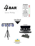
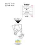
Snapshot
Use on Dimmer
Outdoor Use
Sound Activated
DMX
Master/Slave
Auto-ranging Power Supply
Replaceable Fuse
User Serviceable
Duty Cycle
User Manual
3000 N 29th Ct, Hollywood, FL 33020 U.S.A.
(800) 762-1084 – (954) 929-1115
FAX (954) 929-5560
www.chauvetlighting.com
TABLE OF CONTENTS
1. BEFORE YOU BEGIN ................................................................................................................................................... 3
WHAT IS INCLUDED ................................................................................................................................................................................ 3
UNPACKING INSTRUCTIONS .................................................................................................................................................................... 3
MANUAL CONVENTIONS ......................................................................................................................................................................... 3
ICONS .................................................................................................................................................................................................. 3
SAFETY INSTRUCTIONS .......................................................................................................................................................................... 4
2. INTRODUCTION ........................................................................................................................................................... 5
FEATURES ............................................................................................................................................................................................ 5
FEATURES (FOOTSWITCH) ...................................................................................................................................................................... 5
PRODUCT OVERVIEW............................................................................................................................................................................. 6
3. SETUP .......................................................................................................................................................................... 7
AC POWER........................................................................................................................................................................................... 7
FUSE REPLACEMENT ............................................................................................................................................................................. 7
Orientation ................................................................................................................................................................ 8
Rigging ..................................................................................................................................................................... 8
Tripod Stand ............................................................................................................................................................. 9
4. OPERATING INSTRUCTIONS .................................................................................................................................... 10
FOOTSWITCH OPERATION ..................................................................................................................................................................... 10
Auto ........................................................................................................................................................................ 10
Blackout .................................................................................................................................................................. 10
Sound ..................................................................................................................................................................... 10
5. APPENDIX .................................................................................................................................................................. 11
GENERAL MAINTENANCE...................................................................................................................................................................... 11
GENERAL TROUBLESHOOTING .............................................................................................................................................................. 12
CONTACT US ...................................................................................................................................................................................... 12
RETURNS PROCEDURE ........................................................................................................................................................................ 13
CLAIMS .............................................................................................................................................................................................. 13
TECHNICAL SPECIFICATIONS ................................................................................................................................................................ 14
CHAUVET®, 2010, All Rights Reserved
Information and specifications in this User Manual are subject to change without notice. CHAUVET® assumes no
responsibility or liability for any errors or inaccuracies that may appear in this manual.
1. BEFORE YOU BEGIN
What is included
1 x Mini 4BAR™
1 x Mini 4BAR™ Carrying case
1 x Tripod Stand
1 x Tripod Stand Carrying Case
1 x Wired Footswitch (with 16ft cable)
1 x Warranty Card
1 x User Manual
Unpacking Instructions
Immediately upon receiving a fixture, carefully unpack the carton, check the contents to ensure that
all parts are present, and have been received in good condition. Notify the shipper immediately and
retain packing material for inspection if any parts appear damaged from shipping or the carton itself
shows signs of mishandling. Save the carton and all packing materials. In the event that a fixture
must be returned to the factory, it is important that the fixture be returned in the original factory box
and packing.
Manual Conventions
CHAUVET® manuals use the following conventions to differentiate certain types of information from
the regular text.
MEANING
CONVENTION
[10]
<Menu>
A DIP switch to be configured
A key to be pressed on the fixture’s control panel
1~512
A range of values
50/60
A set of values of which only one can be chosen
Settings
MENU > Settings
ON
A menu option not to be modified (for example, showing the operating
mode/current status)
A sequence of menu options to be followed
A value to be entered or selected
Icons
This manual uses the following icons to indicate information that requires special attention on the part
of the user.
MEANING
ICONS
This paragraph contains critical installation, configuration or operation
information. Failure to comply with this information may render the fixture
partially or completely inoperative, cause damage to the fixture or cause
harm to the user.
This paragraph contains important installation or configuration information.
Failure to comply with this information may prevent the fixture from
functioning correctly.
This paragraph reminds you of useful, although not critical, information.
1. Before You Begin
3
5/7/2010 1:21 PM
Safety Instructions
Please read these instructions carefully. It includes important information
about the installation, usage and maintenance of this product.
Please keep this User Manual for future consultation. If you sell the unit to another user, be sure that
they also receive this instruction booklet.
Always make sure that you are connecting to the proper voltage, and that the line voltage you are
connecting to is not higher than that stated on the decal or rear panel of the fixture.
This product is intended for indoor use only! To prevent risk of fire or shock, do not expose fixture to
rain or moisture.
Make sure there are no flammable materials close to the unit while operating.
The unit must be installed in a location with adequate ventilation, at least 20 in (50 cm) from adjacent
surfaces. Be sure that no ventilation slots are blocked.
Always disconnect from power source before servicing or replacing fuse and be sure to replace with
same fuse source.
Secure fixture to fastening device using a safety chain.
Maximum ambient temperature (Ta) is 104° F (40° C). Do not operate fixture at temperatures higher
than this.
In the event of a serious operating problem, stop using the unit immediately. Never try to repair the
unit by yourself. Repairs carried out by unskilled people can lead to damage or malfunction. Please
contact the nearest authorized technical assistance center.
Never connect the device to a dimmer pack.
Make sure the power cord is never crimped or damaged.
Never disconnect the power cord by pulling or tugging on the cord.
Never carry the fixture directly from the cord. Always use the hanging/mounting bracket.
Avoid direct eye exposure to the light source while it is on.
1. Before You Begin
4
5/7/2010 1:21 PM
2. INTRODUCTION
Features
Complete LED wash system
Includes footswitch with 16 ft cable, tripod with bag and transport case for lights
Safely mounts to truss with clamps
Independent positioning of each light
Low-profile lights are 1.2 in deep
Adjustable stand from 54 in to 85 in
Built-in automated programs
Built-in sound activated programs
Features (footswitch)
Trigger built-in static or automated programs (includes RGB fades)
Instantly triggers sound active mode
Instantly blackout any program
2. Introduction
5
5/7/2010 1:21 PM
Product Overview
Microphone Sensitivity
Adjustment Knob
Tripod Stand
Securing Knob
Back Panel
Microphone
Fuseholder
Lights (4)
Tripod Stand
Mini 4BAR™
Carrying Case
Foot Switch
2. Introduction
6
5/7/2010 1:21 PM
3. SETUP
AC Power
This fixture runs on 100~240 VAC, 50/60 Hz. Before powering on the unit, make sure the line voltage
to which you are connecting it is within the range of accepted voltages.
Always connect the fixture to a switched circuit. Never connect the fixture to a rheostat
(variable resistor) or dimmer circuit, even if the rheostat or dimmer channel is used only as a 0
to 100% switch.
To determine the power requirements for a particular fixture, see the label affixed to the back plate of
the fixture or refer to the fixture’s specifications chart. A fixture’s listed current rating indicates its
average current draw under normal conditions.
Always connect the fixture to a circuit with a suitable electrical ground.
Disconnect the power cord before replacing a fuse and always
replace with the same type fuse.
Fuse Replacement
1.
With a Philips #2 screwdriver unscrew the fuse holder out of its housing.
2.
Remove the damaged fuse from its holder and replace with exact same type fuse.
3.
Insert the fuse holder back in its place and reconnect power.
The fuse is
located here
See the “Technical Specifications” section for the fuse size.
5. Appendix
7
5/7/2010 1:21 PM
Orientation
This fixture may be mounted on the included tripod stand, in any location, provided there is adequate
room for ventilation.
Rigging
There are two methods of mounting this fixture.
Using the included tripod stand
Using a clamp on the two clamp hanging bolts
Adjust the angle of the each of the four lights on the fixture by loosening both knobs and tilting the
fixture. After finding the desired position, retighten both knobs.
o
When selecting installation location, take into consideration access and routine
maintenance.
o
Never mount in places where the fixture will be exposed to rain, high humidity,
extreme temperature changes or restricted ventilation.
o
The clamps for hanging are sold separately.
o
When using the clamp hanging bolts, BOTH of the two hanging positions MUST be
used.
Clamp hanging bolts
(2) two total
Light pan angle
adjustment knob
Light tilt angle
adjustment knob
Both clamps MUST be USED
when truss-mounting!
5. Appendix
8
5/7/2010 1:21 PM
Tripod Stand
This fixture may be mounted on the included tripod stand.
1.
2.
3.
4.
5.
6.
7.
8.
9.
Setup the Tripod stand on a sturdy platform that is capable of holding at least 10 times the
weight of the stand with Mini 4BAR™.
Use the Tripod Legs Adjustment Knob to slide open the legs and set the tripod to a safe
operating level.
Adjust the stand height to the minimum operating height level using the Height Adjustment
Knob and the safety pin. The Safety Pin must be used.
Attach the Mini 4BAR™ to the tripod stand.
Using the Tripod Stand Securing Knob, hand-tighten the Mini 4BAR to the stand.
After confirming that the Safety Pin is removed, carefully and slowly loosen the Height
Adjustment Knob to allow the height of the stand to be increased. The top of the stand may
drop quickly, so be careful to control this and be aware of personal safety!
Raise the stand to the desired height and hand-tighten the Height Adjustment Knob. Then,
insert the Safety Pin to secure the height of the stand.
Plug the fixture into power.
Plug the 3-pin footswitch into the fixture for control.
There is a safety pin included, which MUST be used. There are 6 positions that this stand
may be set to, and 6 holes to attach the safety pin. After the 6th position, there will be a
warning sign that says “STOP!” Do not move the stand height past this point!
Height Adjustment
Knob
Safety Pin
Tripod Legs
Adjustment Knob
5. Appendix
9
5/7/2010 1:21 PM
4. OPERATING INSTRUCTIONS
Pedal #1
(Auto Program Selection)
Pedal #2
(Blackout)
Footswitch operation
The included footswitch provides quick access to preset colors, color change programs, and sound
triggering via the onboard microphone on the Mini 4BAR™. Please see the chart, along with the set of
instructions, below for further explanation.
1.
2.
Power on the fixture.
Connect the footswitch to the Mini 4BAR™ via the 3-pin connection cable with plug.
Auto
Press pedal #1 to scroll through the auto programs and the static colors.
Blackout
Press pedal #2 to activate the Blackout function.
Sound
Press pedals #1 & #2 simultaneously to activate sound operation.
PEDAL
1 (PRESET)
2 (BLACKOUT)
SUB-OPTION
FUNCTION
1 x press
Auto program-color change
2 x press
Auto program-color fade
3 x press
Red
4 x press
Green
5 x press
Blue
6 x press
Cyan
7 x press
Magenta
8 x press
Yellow
9 x press
White
-
Blackout
The fixture will start up in sound mode when first powered ON.
The fixture will cycle through the auto programs and static colors very rapidly if pedal #1 is held down.
This will seem like a very fast auto program. When releasing the pedal, the fixture will stop on the
program in the cycle.
After activating Blackout, pedal #2 will NOT release the blackout. Press pedal #1 to activate Auto mode,
or press pedals #1 & 2 simultaneously to activate Sound mode.
5. Appendix
10
5/7/2010 1:21 PM
5. APPENDIX
General Maintenance
To maintain optimum performance and minimize wear, fixtures should be cleaned frequently. Usage
and environment are contributing factors in determining frequency. As a general rule, fixtures should
be cleaned at least twice a month. Dust build up reduces light output performance and can cause
overheating. This can lead to reduced lamp life and increased mechanical wear. Be sure to power off
fixture before conducting maintenance.
Unplug fixture from power.
Use a vacuum or air compressor and a soft brush to remove dust collected on external
vents.
Clean all glass when the fixture is cold with a mild solution of glass cleaner or Isopropyl
Alcohol and a soft lint free cotton cloth or lens tissue.
Apply solution to the cloth or tissue and drag dirt and grime to the outside of the lens.
Gently polish optical surfaces until they are free of haze and lint.
The cleaning of external optical lenses and/or mirrors must be carried out periodically to optimize light
output. Cleaning frequency depends on the environment in which the fixture operates. Damp, smoky
or particularly dirty surroundings can cause greater accumulation of dirt on the unit’s optics. Clean
with soft cloth using normal glass cleaning fluid. Clean the external optics at least every 20 days.
Clean the fixture at least every 30/60 days.
Always dry the parts carefully after cleaning them.
Never spin a fan using compressed air.
5. Appendix
11
5/7/2010 1:21 PM
General Troubleshooting
SYMPTOM
Blown Fuse/
Tripped Breaker
Device does not
power up
Fixture is not
responding to
DMX
Loss of signal
POSSIBLE CAUSE(S)
POSSIBLE ACTION(S)
Short circuit along the power wires
Replace Fuse
Excessive circuit load
Reset Breaker
No power
Check for power on power outlet
Loose power cord
Check power cord
Blown Fuse
Replace Fuse
Reset Breaker
Reset Breaker
Wrong DMX addressing
Check Control Panel and unit
addressing
Damaged DMX cables
Check DMX cables
Wrong polarity settings on the controller
Check polarity switch settings on the
controller
Loose DMX cables
Check cable connections
Faulty DMX interface
Replace DMX input
Faulty Main PCB
Replace Main PCB
Bouncing signals
Install terminator as suggested
Long cable / Low level signal
Interference from AC wires
Install amplifier right after fixture with
strong signal
Keep DMX cables separated from
power cables or black lights
If you still have a problem after trying the above solutions, please contact CHAUVET®
Technical Support.
Contact Us
World Wide
5. Appendix
General Information
CHAUVET®
3000 North 29th Court
Hollywood, FL 33020
voice: 954.929.1115
fax:
954.929.5560
toll free: 800.762.1084
Technical Support
CHAUVET®
3000 North 29th Court
Hollywood, FL 33020
voice: 954.929.1115 (Press 4)
fax:
954.929.5560 (Attention: Service)
World Wide Web
www.chauvetlighting.com
12
5/7/2010 1:21 PM
Returns Procedure
Returned merchandise must be sent prepaid and in the original packing; call tags will not be issued.
Package must be clearly labeled with a Return Merchandize Authorization Number (RMA #).
Products returned without the RMA # will be refused. Call CHAUVET® and request an RMA # prior to
shipping the fixture. Be prepared to provide the model number, serial number and a brief description
of the cause for the return. Be sure to pack fixture properly; any shipping damage resulting from
inadequate packaging is the customer’s responsibility. As a suggestion, proper UPS packing or
double-boxing is always a safe method to use.
CHAUVET® reserves the right to use its own discretion to repair or replace product(s).
If you are given an RMA #, please include the following information on a piece of paper inside
the box:
1)
Your name
2)
Your address
3)
Your phone number
4)
The RMA #
5)
A brief description of the symptoms
Claims
Damage incurred in shipping is the responsibility of the shipper; therefore, the damage must be
reported to the carrier upon receipt of merchandise. It is the customer's responsibility to notify and
submit claims with the shipper in the event that a fixture is damaged due to shipping. Any other claim
for items such as missing component/part, damage not related to shipping, and concealed damage,
must be made within seven (7) days of receiving merchandise.
5. Appendix
13
5/7/2010 1:21 PM
Technical Specifications
WEIGHT & DIMENSIONS
Length ............................................................................................................................... 3 in (76 mm)
Width............................................................................................................................. 38 in (965 mm)
Height (light fixture only, NOT mounted on the included stand) ....................................... 9 in (229 mm)
Height (using the stand) ............................................................................ 54~85 in (1,372~2,159 mm)
Weight (includes the light fixture, footswitch, and tripod stand) .................................... 16.9 lbs (7.7 kg)
POWER
Auto-ranging power supply ..............................................................................100~240 VAC, 50/60 Hz
Power consumption @ 120 VAC, 60 Hz ................................................34 W (0.5 A) max, 0.2 A inrush
Power consumption @ 230 VAC, 50 Hz ................................................34 W (0.3 A) max, 0.2 A inrush
Fuse.................................................................................................................................. F 1 A, 250 V
LIGHT SOURCE
LED........................................................ 300 (75 per light) (100 red, 100 green, 100 blue) 100,000 hrs
PHOTO OPTIC
Beam Angle .................................................................................................................................... 16°
Field Angle ...................................................................................................................................... 26°
Intensity ................................................................................................................................. 1,160 lux
THERMAL
Maximum ambient temperature ...................................................................................... 104° F (40° C)
ORDERING INFORMATION
Mini 4BAR™ ........................................................................................................................ MINI4BAR
WARRANTY INFORMATION
Warranty ........................................................................................................... 1-year limited warranty
Technical Specifications
14
5/7/2010 1:21 PM