1
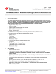
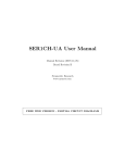
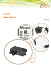
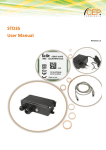
OBSOLETE
LM3647
www.ti.com
SNOS517H – MARCH 2000 – REVISED APRIL 2013
LM3647 Universal Battery Charger for Li-Ion, Ni-MH and Ni-Cd Batteries
Check for Samples: LM3647
FEATURES
DESCRIPTION
•
•
The LM3647 is a charge controller for Lithium-Ion (LiIon), Nickel-Metal Hydride (Ni-MH) and NickelCadmium (Ni-Cd) batteries. The device can use
either a pulsed-current charging or a constant-current
charging technique. The device can also be
configured to discharge before charging. Throughout
the charging sequence the LM3647 monitors voltage
and/or temperature and time in order to terminate
charging.
1
2
•
•
•
•
•
•
•
Auto-Adaptive Fast Charge
High-Resolution, Accurate Voltage Monitoring
Prevents Li-Ion Undercharge or Overcharge
Fast Charge, Pre-Charge and Maintenance
Currents are Provided. Different Currents are
Selectable via External Resistors
Fast-Charge Termination by Δ Temperature/Δ
Time, Maximum Voltage, Maximum
Temperature, Negative Δ Voltage and
Maximum Time
Dynamically Detects Battery Insertion,
Removal, Short Circuit and Bad Battery
Without Additional Hardware
Supports Charging of Battery Packs with 2–8
Cells of Ni-Cd/Ni-MH or 1–4 Cells of Li-Ion (1
Cell of NiCd/NiMH can be Supported by Added
External 2x Voltage Amplifier)
Three Optional LED Indicators and Buzzer
Output Indicate Operational Modes
Ni-MH/Ni-Cd Charge Mode, Li-Ion Charge Mode
or Discharge Mode can be Selected Manually
Supports Control of Current Feedback Power
Supply and Constant Current Power Supply
APPLICATIONS
•
Battery Charging Systems for:
– Portable Consumer Electronics
– Audio/Video Equipment
– Communications Equipment
– Point of Sale Devices
– Power Tools
– Personal Convenience Products
Charge Termination Methods are:
• Negative Delta Voltage (−ΔV)
• Optional: Delta Temperature/Delta Time (ΔT/Δt)
• Backup: Maximum Temperature
• Backup: Maximum Time
• Backup: Maximum Voltage
If both voltage and temperature fail to trigger the
termination requirements, then the maximum time
(configured by external hardware) steps in which
terminates the charging.
In Ni-Cd/Ni-MH mode, four different charging stages
are used:
• Soft-Start Charge
• Fast Charge
• Topping Charge
• Maintenance Charge
In Li-Ion mode, four different charging stages are
used:
• Qualification
• Fast Charge Phase 1, Constant Current
• Fast Charge Phase 2, Constant Voltage
• Maintenance Charge
The charge current of the LM3647 is configured via
external resistors, which in turn controls the duty
cycle of the PWM switching control output. For costsensitive applications, the LM3647 charge controller
cab be configured to use an external current source
and no temperature sensor.
1
2
Please be aware that an important notice concerning availability, standard warranty, and use in critical applications of
Texas Instruments semiconductor products and disclaimers thereto appears at the end of this data sheet.
All trademarks are the property of their respective owners.
PRODUCTION DATA information is current as of publication date.
Products conform to specifications per the terms of the Texas
Instruments standard warranty. Production processing does not
necessarily include testing of all parameters.
Copyright © 2000–2013, Texas Instruments Incorporated
OBSOLETE
LM3647
SNOS517H – MARCH 2000 – REVISED APRIL 2013
www.ti.com
DESCRIPTION (CONTINUED)
When using an external current source, the current is controlled by the LM3647 which turns the current source
on and off. The LM3647 automatically detects the presence of a battery and starts the charging procedure when
the battery is installed. Whenever an error occurs (e.g., short circuit, temperature too high, temperature too low,
bad battery, charge time over, and so on.) the LM3647 will stay in error mode until the battery is removed or it
gets within the allowed charging temperature range. The LM3647 is available in a standard 20-lead SOIC surface
mount package.
CONNECTION DIAGRAM
Figure 1. Top View
See Package SOIC (DW)
Table 1. PIN DESCRIPTIONS
Pin No.
2
Name
I/O
Description
1
SEL3
I
Input to Select Power Source or Li-Ion Cell Voltage
2
SEL4
I
Input to Select Maintenance Charge Time Out, Connected to an RC-Network
3
RCIN
RC-Timing Pin
4
GND
Ground
5
VCC
6
RESET
I
Reset Pin, Active Low
7
LED1
O
LED Output
8
LED2
O
LED Output
9
LED3
O
LED Output
10
VREF
I
Voltage Reference Analog Input
11
CEXT
12
CEL
I
Battery Voltage Input (through resistor divider)
13
CS
I
Current Sense Input
14
TEMP
I
NTC-Temperature Sensor Input
15
DISCHG
O
High when Discharging, Else Low
16
SYSOK
O
System Monitor Output
17
BUZZER
O
Buzzer Output
18
PWM
O
Charge Control Output
19
SEL1
I
Tri-Level Input, Discharge/Maintenance Charge Select
20
SEL2
I
Tri-Level Input, Battery Type Select (NiCd, NiMH, Li-Ion)
5V, Power Supply
External Capacitor
Submit Documentation Feedback
Copyright © 2000–2013, Texas Instruments Incorporated
Product Folder Links: LM3647
OBSOLETE
LM3647
www.ti.com
SNOS517H – MARCH 2000 – REVISED APRIL 2013
TYPICAL APPLICATION
Submit Documentation Feedback
Copyright © 2000–2013, Texas Instruments Incorporated
Product Folder Links: LM3647
3
OBSOLETE
LM3647
SNOS517H – MARCH 2000 – REVISED APRIL 2013
www.ti.com
These devices have limited built-in ESD protection. The leads should be shorted together or the device placed in conductive foam
during storage or handling to prevent electrostatic damage to the MOS gates.
ABSOLUTE MAXIMUM RATINGS (1) (2)
Supply Voltage (VCC)
7V
−0.3V to VCC +0.3V
Voltage at Any Pin
Total Current into VCC Pin (Source)
100 mA
Total Current out of GND Pin (Sink)
110 mA
Storage Temperature Range
(1)
(2)
-65°C to +140°C
Absolute Maximum Ratings indicate limits beyond which damage to the device may occur. DC and AC Electrical Specifications are not
ensured when operating the device at absolute maximum ratings.
If Military/Aerospace specified devices are required, please contact the Texas Instruments Sales Office/ Distributors for availability and
specifications.
DC ELECTRICAL CHARACTERISTICS
−40°C ≤ TA ≤ +85°C unless otherwise specified.
Parameter
Conditions
Operating Voltage
Min
Typ
4.5
Supply Current
Max
5.5
2.5
LED-pin Sink Current
7.5
Units
V
mA
15
mA
Temperature Input Levels
Ni-Cd/Ni-MH Upper Limit
(Voltage at TEMP-pin)
3.15
V
Li-Ion Upper Limit
(Voltage at TEMP-pin)
3.0
V
Lower Limit
(Voltage at TEMP-pin)
0.5
V
Start Limit
(Voltage at TEMP-pin)
2.2
V
L-Ion (for both 4.1 and 4.2V Cells)
Maintenance Charge Minimum Voltage
(CEL pin)
2.6
V
Maintenance Charge Restart Voltage
(CEL pin)
2.153
V
Good Battery Threshold
(CEL pin)
1.2
V
Maintenance Current
(Voltage at CS-pin)
2.3
V
Maintenance Current Lower Threshold
(Voltage at CS-pin)
2.42
V
Minimum Current Fast Charge Termination
(Voltage at CS-pin)
2.3
V
Qualification Current
(Voltage at CS-pin)
2.3
V
Maximum Charging Current
(Voltage at CS-pin)
1.5
V
3.017
V
Ni-Cd/Ni-MH
Maximum Battery Voltage
(CEL pin)
Maximum Battery Current
(Voltage at CS-pin)
1.5
V
Battery Presence Limit
(CEL pin)
1.0
V
Discharged Battery Limit
(CEL pin)
1.7
V
Good Battery Threshold
(CEL pin)
1.2
V
Soft Start Current
(Voltage at CS-pin)
2.3
V
Topping Charge Current
(Voltage at CS-pin)
2.3
V
Maintenance Charge Current
(Voltage at CS-pin)
2.45
V
2.425
VREF
2.5
V
Max
Units
AC ELECTRICAL CHARACTERISTICS
Parameter
RCIN Frequency
Conditions
Min
Typ
2.5
MHz
Fast-PWM Frequency
250
Hz
Slow-PWM Frequency
0.1
Hz
4
R = 3.3 kΩ, C = 68 pF
Submit Documentation Feedback
Copyright © 2000–2013, Texas Instruments Incorporated
Product Folder Links: LM3647
OBSOLETE
LM3647
www.ti.com
SNOS517H – MARCH 2000 – REVISED APRIL 2013
FUNCTIONAL DESCRIPTION
GENERAL
The LM3647 can be configured to charge three different types of batteries: Ni-Cd, Ni-MH and Li-Ion. The charger
behavior for Ni-Cd and Ni-MH is similar but the charge curves will appear slightly different due to the differences
in chemistry. The Ni-Cd/Ni-MH charging algorithm is divided into four phases:
Soft Start: The LM3647 detects that a battery is connected and optionally verifies that the temperature is within
safe operating limits (approx. −5°C to +50°C). Charging starts with a current of 0.2C and switches into the
next phase after approx. 5 minutes. Error termination will be triggered by Maximum Battery Voltage (CELpin > 3.017V) or if the battery voltage does not reach the defective battery level (CEL-pin < 1.2V).
Fast Charge: Constant current is applied to the battery and the LM3647 monitors voltage and temperature
(optional). Switching into the next phase will appear after a voltage drop in the charging curve: Ni-Cd ∼ 50
mV/cell and Ni-MH ∼ 17 mV/cell. Error termination will be triggered by over-temperature.
Topping Charge: A current of 0.2C is applied to the battery for a user defined time (RC network at SEL4).
Maintenance Charge: Is user selectable and is a fixed percentage of the Fast Charge rate. Discharge before
charge is user selectable.
Figure 2. Ni-Cd Charging Curve
Figure 3. Ni-MH Charging Curve
The Li-Ion charging algorithm is also divided into four phases:
• Qualification: The LM3647 detects that a battery is connected and verifies that the temperature (optional but
highly recommended for safety reasons) is within limit. Charging starts with a current of 0.2C and switches
into next phase after approx. 1 minute. Error termination will be triggered if the battery voltage does not
reach the Li-Ion battery qualification level (CEL-pin < 1.2V) within one minute.
• Fast Charge Constant Current: Battery voltage will rise until Maximum Battery Voltage (CEL-pin = 2.675V
or 2.74V depending on SEL3) is reached.
• Fast Charge Constant Voltage: Keeps the voltage constant until the current has decreased below the
threshold (CS at 2.3V).
• Maintenance Charge: Is user selectable and is a fixed percentage of the Fast Charge rate.
Figure 4. Li-Ion Charging Curve
Submit Documentation Feedback
Copyright © 2000–2013, Texas Instruments Incorporated
Product Folder Links: LM3647
5
OBSOLETE
LM3647
SNOS517H – MARCH 2000 – REVISED APRIL 2013
www.ti.com
ADVANCED PIN DESCRIPTIONS
SEL1 is a selection pin to control the LM3647 discharge and maintenance charge modes. The pin has three
states: tied to VCC, GND, or unconnected (Hi-Z). When the charger is configured to charge Ni-Cd or Ni-MH
batteries, this pin determines if the charger discharges the battery before charging or if the charger shall only
maintenance charge the battery. When the charger is configured for Li-Ion batteries, this pin determines how the
charger behaves during maintenance charge.
Charge mode
condition SEL2 = GND (NiCd) or VCC (NiMH)
SEL1
VCC
No discharge before charge
GND
Maintenance charge only (no fast charge)
Open
Discharge before charge
Charge mode
condition SEL2 = Open (Li-Ion)
SEL1
VCC
Maintenance charge indefinite
GND
Maintenance charge indefinite, restart fast-charge if battery gets discharged (load connected)
Open
No maintenance charge, restart fast charge if battery becomes discharged
SEL2 is a selection pin to determine the battery type to be charged. The pin has three states: tied to VCC (NiMH), GND (Ni-Cd), or unconnected (Li-Ion).
SEL2
Battery Type Select
VCC
Ni-MH
GND
NiCd
Open
Li-Ion
SEL3 is a selection pin used to set charger hardware modes. The pin has two states: tied to VCC or GND. When
the LM3647 is configured for Ni-Cd/Ni-MH batteries, this pin selects between a power supply with current
feedback when tied to VCC (PWM “fast” frequency) or a constant current source when tied to GND (PWM “slow”
frequency). When configured for Li-Ion batteries, SEL3 switches between 4.1V cells or 4.2V cells.
NOTE
SEL3 must be hard wired to VCC if a charger that supports both Li-Ion and Ni-Cd/Ni-MH is
implemented.
PWM Output Frequency Select
output SEL2 = VCC (NiMH) or GND (NiCd)
SEL3
VCC
Current feedback (“fast” PWM frequency)
GND
No current feedback (external constant current source) (“slow” PWM frequency)
Li-Ion Cell Voltage Select
output SEL2 = Open (Li-Ion)
SEL3
VCC
4.2V/cell
GND
4.1V/cell
NOTE
Current feedback is automatically selected, if LM3647 is configured for Li-Ion charging (pin
SEL2 open).
SEL4 is connected to a RC-network that determines the charge time-outs. This RC-network is also connected to
the output LED1. (See CHARGE TIMEOUT for details).
RCIN is a high-speed timing pin connected to a RC-network, used to drive the charger at the right operating
frequency.
GND is the ground pin.
VCC
is the power-supply pin. This pin should have a 100 nF decoupling capacitor tied to GND.
6
Submit Documentation Feedback
Copyright © 2000–2013, Texas Instruments Incorporated
Product Folder Links: LM3647
OBSOLETE
LM3647
www.ti.com
SNOS517H – MARCH 2000 – REVISED APRIL 2013
RESET is a reset pin.
LED1 is an active-low output used to indicate charge phase. It is also used when measuring the charge timeout
value.
LED2 is an active-low output used to indicate charge or discharge. It also sends out digitally what the LM3647
has read at the mode selection pins and charge timeout.
LED3 is an active-low output used to indicate charge start/stop and error.
VREF is the voltage reference analog input. The LM3647 uses this pin as a reference when measuring the other
analog inputs. VREF has to be connected to a 2.5V voltage reference (for example, LM4040A - 2.5).
CEXT is a timing pin used by the LM3647, it must be connected to a low loss capacitor (polyester).
CEL
is an analog input that measures the battery voltage via a resistor divider network.
CS
is an analog input that is connected to a differential amplifier that measures the voltage over a small
current sensing resistor, when used in conjunction with current feedback power supply. When the LM3647
is used with a constant current power supply, CS should be connected to the 2.5V voltage reference (pin
VREF).
TEMP is an analog input that is connected to the temperature sensing NTC-resistor (is used). If no temperature
sensor is used, the input must be connected to a voltage between 0.5V to 2.2V.
DISCHG is a digital output that controls a power-FET that discharges the batteries before charging them. If the
discharge function is not used, leave this pin unconnected.
SYSOK is an open drain output that resets the LM3647 in the rare case of an internal illegal operating condition.
This pin is connected to the RESET pin to increase reliable operation of the device in hostile operating
environments (for example, noisy environments).
BUZZER is a digital output that controls a small FET and turns an optional buzzer on and off. The buzzer must
have it's own oscillator drive circuitry.
PWM is a digital output that controls the charge voltage or turns the external current source on and off
(depending on mode-selection).
CONFIGURATIONS
MAXIMUM BATTERY VOLTAGE
The maximum battery voltage corresponds to the number of battery cells. The resistor network in the figure
below scales the battery voltage to a level suitable for the LM3647. For Ni-Cd/Ni-MH batteries the tolerance of
the network is not critical, and only defines the maximum battery voltage (which is used as a backup termination
method). For Li-Ion batteries the network must be more accurate, and resistors with low tolerances must be used
(1% or better).
NI-CD/NI-MH
Each battery cell is at nominal voltage 1.2V, but the critical voltage is rather the maximum voltage per cell
specified at 1.85V. The maximum cell voltage is used for maximum voltage error termination. If a Ni-Cd/Ni-MH
cell fails, it either becomes shorted or goes high impedance. In the case of high impedance the cell voltage will
reach 1.85V. By multiplying the number of cells with the maximum cell voltage, the Maximum Battery Voltage
(VBatm) is achieved.
When the maximum battery voltage has been determined, the voltage divider network can be dimensioned using
the Equation 1 (SEL2 connected to VCC or GND):
(1)
Submit Documentation Feedback
Copyright © 2000–2013, Texas Instruments Incorporated
Product Folder Links: LM3647
7
OBSOLETE
LM3647
SNOS517H – MARCH 2000 – REVISED APRIL 2013
www.ti.com
Table 2. Resistor network selection Quick Guide
No. of Cells
Ni-Cd/Ni-MH
Nominal
Max
R6
R7
2
2.4V
3.7V
10k
43k
3
3.6V
5.55V
47k
56k
4
4.8V
7.4V
16k
11k
5
6V
9.25V
62k
30k
6
7.2V
11.1V
15k
5.6k
7
8.4V
12.95V
27k
8.2k
8
9.6V
14.8V
39k
10k
9
10.8V
16.65V
68k
15k
10
12V
18.5V
22k
3.9k
Example: A standard 9V Ni-Cd block battery is composed of 6 small Ni-Cd cells and therefore has a nominal
voltage of 7.2V. See Table 2 for resistor values.
8
Submit Documentation Feedback
Copyright © 2000–2013, Texas Instruments Incorporated
Product Folder Links: LM3647
OBSOLETE
LM3647
www.ti.com
SNOS517H – MARCH 2000 – REVISED APRIL 2013
LI-ION
The voltage divider network for Li-Ion must be selected with great care for maximum utilization of the batteries.
Li-Ion battery cells have a nominal voltage of 3.6V or 3.7V and the maximum voltage per cell is specified at 4.1V
or 4.2V respectively. By multiplying the number of battery cells with the maximum cell voltage, it is possible to
determine the Maximum Voltage of the Battery Pack. When the maximum battery voltage (VBatm) has been
determined, the voltage divider network has to be dimensioned using Equation 2 and Equation 3 (SEL2 open):
Pin SEL3
GND
(2)
VCC
(3)
The LM3647 supports two different user selectable battery input voltages on the CEL pin. These are 2.675V
(SEL3 tied to GND) and 2.740V (SEL3 tied to VCC). This selection pin can be used to configure the charger to
handle both 3.6V and 3.7V Li-Ion-cells, without changing the resistor values in the CEL pin voltage divider
network. SEL3 can also be used to obtain a better match when choosing standard series resistor values for
certain cell combinations.
Table 3. Resistor network selection Quick Guide
No. of Cells
Li-Ion (3.6V cell)
Nominal
Max
R6
R7
1
3.6V
4.1V
16k
30k
2
7.2V
8.2V
62k
30k
3
10.8V
12.3V
27k
7.5k
4
14.4V
16.4V
22k
3.9k
No. of Cells
Li-Ion (3.7V cell)
Nominal
Max
R6
R7
1
3.7V
4.2V
16k
30k
2
7.4V
8.4V
62k
30k
3
11.1V
12.6V
27k
7.5k
4
14.8V
16.8V
22k
3.9k
Submit Documentation Feedback
Copyright © 2000–2013, Texas Instruments Incorporated
Product Folder Links: LM3647
9
OBSOLETE
LM3647
SNOS517H – MARCH 2000 – REVISED APRIL 2013
www.ti.com
CHARGE TIMEOUT
The LM3647 uses the charge timeout value as a backup termination method if the normal termination methods
fail. The charge timeout also controls the length of some of the phases, (for example, the Topping Charge
phase). The timeout is selectable by choosing different R-C values as shown in the table below:
R Value
C Value
Ni-Cd/Ni-MH Fast
Charge (minutes)
Ni-Cd/Ni-MH
Topping (minutes)
Li-Ion CC
(minutes)
Li-Ion CV
(minutes)
100 kΩ
0 nF
75
20
50
75
100 kΩ
10 nF
100
25
70
100
100 kΩ
15 nF
160
40
110
160
100 kΩ
22 nF
190
50
130
190
100 kΩ
33 nF
260
65
170
260
100 kΩ
47 nF
330
80
220
330
100 kΩ
68 nF
450
115
300
450
100 kΩ
100 nF
540
135
360
540
CHARGE CURRENT
Charge current selection depends on the type of power supply used. The LM3647 supports two types: current
feedback and constant current. The PWM pin is used to control the power supply and depending on the supply
type, it either produces a simple on/off signal (PWM slow, constant current supply) or a PWM signal that is
filtered externally to a DC voltage to regulate the charge voltage in a current feedback power supply (PWM fast).
(SEL3 = VCC, if SEL2 = GND or VCC; automatic if SEL2 = open.)
CURRENT FEEDBACK POWER SUPPLY
A current feedback type power supply must be used if charging Li-Ion batteries. When a current feedback power
supply is used, the charge-current is selected by setting the current sensing resistor and the gain of the
differential amplification stage. The current sensing resistor (R5) should be dimensioned such that a voltage drop
over it is not too small, because the signal will be more susceptible to noise and offsets in the amplificationstage. The resistance should not be too large either (especially in high-current applications), because this will
only generate more heat from the component. A suitable value is one that develops about 50 mV across the
resistor when maximum current flows through it.
The current-sensing signal is amplified, inverted and centered on the 2.5V reference by the operational amplifier
and fed into the CS pin on the LM3647. The amplification stage must be dimensioned by setting the appropriate
ratio between R1 (R2) and R3 (R4). The figure above is dimensioned for a maximum current of about 1.1A. This
was calculated using Equation 4:
(4)
Example:
R3 = 5.1 kΩ, R1 = 100 kΩ, R5 = 0.047Ω, VREF = 2.5V
→ MaxCurrent ≈ 1.09 Ampere
10
Submit Documentation Feedback
(5)
Copyright © 2000–2013, Texas Instruments Incorporated
Product Folder Links: LM3647
OBSOLETE
LM3647
www.ti.com
SNOS517H – MARCH 2000 – REVISED APRIL 2013
With a current feedback power supply the PWM pin must be configured for “fast” mode (SEL3 = VCC; if SEL2 =
GND or VCC; automatic if SEL2 = open).
The RC-network R6, C9 and R5, C1||C2 lowpass-filters the PWM-signal from the LM3647 to a DC-level that is
fed into the operational amplifier. The resistor R22 is required to prevent DC-output before the LM3647 has
control of the RC-networks.
CONSTANT CURRENT POWER SUPPLY
A constant current power supply can only be used with Ni-Cd/Ni-MH batteries, it can not be used to charge LiIon batteries. With a constant current power supply (NiCd/NiMH batteries only: SEL2 = GND or VCC) the PWM
pin must be configured for “slow” mode (SEL3 = GND). In that mode the PWM-pin turns the external current
source on and off at a rate of 0.1 Hz. (This example is just one of many possible design solutions.) The PWM-pin
(SLOW_PWM) turns the transistor Q1 on and off. When the transistor is off the current source is on, and when
the transistor is on the current source is off (V_OUT at approximate 0.7V). The value of R1 depends on the size
of the charge current (see Equation 6):
(6)
The charge current duty cycles for the different phases cycles are listed below:
Charge Phase
Charge Current Duty Cycle
Soft Start
10%
Fast Charge
100%
Topping Charge
10%
Maintenance Charge
5%
Submit Documentation Feedback
Copyright © 2000–2013, Texas Instruments Incorporated
Product Folder Links: LM3647
11
OBSOLETE
LM3647
SNOS517H – MARCH 2000 – REVISED APRIL 2013
www.ti.com
DIMENSIONING THE RESET CIRCUITRY
The reset-circuitry is designed to hold the RESET pin low until the power supply to the LM3647 has stabilized.
The RC-network (R21 and C4) should be dimensioned in the following way:
(R21 × C4) > 5×PowerSupplyRiseTime
(7)
The diode D2 discharges the capacitance C4 when power loss occurs. The resistor R20 is used to protect the
SYSOK-pin, and its value is not critical (typical value is 2 kΩ). R20 can be eliminated if the SYSOK pin is not
connected to RESET or if the value of C4 is ≤0.1 µF. The connection between RESET and SYSOK is optional
but highly recommended for safe operation of the LM3647.
DIMENSIONING THE RCIN CIRCUITRY
The RC-circuitry is designed to time the charger so it charges and regulates at the correct frequency. The values
of the R and C are important, because a change in the RC-value gives a higher or lower operating frequency
which affects charge quality. The capacitance should be a ceramic type and preferably an NP0 type, which gives
the least frequency deviation with temperature change.
DIMENSIONING THE DISCHARGE CIRCUITRY
The discharge-circuitry controls the discharge rate during the discharge phase (if used). The discharge output
turns on the transistor Q2, and a current flows from the battery through the discharge resistor R8. The current
through R8 depends on battery voltage and the value of R8. This value depends on the maximum discharge rate
for the battery pack. The approximate value can be calculated using Equation 8:
(8)
The resistor R7 keeps the transistor Q2 off until the LM3647 has been powered up and is in control of the
circuitry.
12
Submit Documentation Feedback
Copyright © 2000–2013, Texas Instruments Incorporated
Product Folder Links: LM3647
OBSOLETE
LM3647
www.ti.com
SNOS517H – MARCH 2000 – REVISED APRIL 2013
BUZZER OUTPUT CIRCUITRY
The buzzer-circuitry turns the transistor Q3 on when the buzzer should sound. If the current consumption for the
buzzer is lower than 0.3 mA then the buzzer may be directly connected to the BUZZER-pin. Please note that the
BUZZER-pin does not generate a PWM-signal, therefore the buzzer must have its own oscillator circuitry. If an
electromagnetic buzzer is used, then the transistor may need a reverse-biased diode to protect it from harmful
voltage spikes.
USER INTERFACE
The user interface consists of up to three LEDs and one buzzer. The LEDs have four different states:
On, off, slow flash (∼1 Hz) and fast flash (∼10 Hz). The buzzer has three different states: off, one short beep
(∼100 ms) and one long beep (∼1s).
The user interface is designed in a flexible way. Use of the buzzer or the LEDs is optional, depending on design
requirements. It is possible to use the LM3647 with one, two or all three LEDs.
A single “end of charge” Status LED can be implemented with a 2-input NAND gate on pins LED1 and LED3. In
this implementation, note that a pull-up resistor is required on LED1 and LED3.
Table 4. Ni-Cd/Ni-MH User Interface Scheme
Charge Phase
LED1 Status
LED2 Status
LED3 Status
Buzzer Status
No Battery
Off
Off
Off
Off
New Battery/Temp-Test
Fast Flash
Off
Off
Short Beep
Softstart Charge
Slow Flash
Off
Off
Off
Charging
On
Slow Flash
Off
Off
Topping Charge
On
Fast Flash
Off
Off
Maintenance
On
Off
On
Long Beep
Discharge
Off
Slow Flash
Off
Off
Temperature Error
2 Fast Flashes
Off
On
Short Beep
Error
Fast Flash
Off
Fast Flash
Short Beep
Submit Documentation Feedback
Copyright © 2000–2013, Texas Instruments Incorporated
Product Folder Links: LM3647
13
OBSOLETE
LM3647
SNOS517H – MARCH 2000 – REVISED APRIL 2013
www.ti.com
Table 5. Li-Ion User Interface Scheme
Charge Phase
LED1 Status
LED2 Status
LED3 Status
Buzzer Status
No Battery
Off
Off
Off
Off
New Battery/Temp-Test
Fast Flash
Off
Off
Short Beep
Qualification Charge
Slow Flash
Off
Off
Off
Charging CC
On
Slow Flash
Off
Off
Charging CV
On
Fast Flash
Off
Off
Maintenance
On
Off
On
Long Beep
Temperature Error
2 Fast Flashes
Off
On
Short Beep
Error
Fast Flash
Off
Fast Flash
Short Beep
RECOMMENDED DIMENSIONING FOR THE TEMPERATURE SENSOR
The LM3647 is designed for use with a NTC resistor as a temperature sensor. The NTC should have 3 kΩ @
25°C and a β = 3988. The voltage at TEMP-input must be between 2.2V and 0.5V for the charger to start. While
charging, the voltage must stay between 3.0V (maximum temperature) for Li-Ion, or 3.15V (maximum
temperature) for Ni-Cd/Ni-MH, and 0.5V (minimum temperature) or the charger will register a temperature fault
and abort the charge. These voltages correspond to the upper and lower limits for the battery pack temperature.
When no NTC is used the TEMP-input pin must be connected to a voltage level between 2.2V and 0.5V.
Figure 5. Typical Configuration Curve, (NTC Characteristics: 3 kΩ @ 25°C, β=3988)
14
Submit Documentation Feedback
Copyright © 2000–2013, Texas Instruments Incorporated
Product Folder Links: LM3647
OBSOLETE
LM3647
www.ti.com
SNOS517H – MARCH 2000 – REVISED APRIL 2013
TYPICAL CIRCUIT CONFIGURATIONS
Figure 6. Common Circuitry Used for both Ni-Cd/Ni-MH and Li-Ion
Submit Documentation Feedback
Copyright © 2000–2013, Texas Instruments Incorporated
Product Folder Links: LM3647
15
OBSOLETE
LM3647
SNOS517H – MARCH 2000 – REVISED APRIL 2013
www.ti.com
Figure 7. Circuitry Used Only for Ni-Cd/Ni-MH
16
Submit Documentation Feedback
Copyright © 2000–2013, Texas Instruments Incorporated
Product Folder Links: LM3647
OBSOLETE
LM3647
www.ti.com
SNOS517H – MARCH 2000 – REVISED APRIL 2013
Figure 8. Circuitry Used for Li-Ion
NOTE
D7 is required to protect Q4 from reverse current.
Can also be used for Ni-Cd and Ni-MH if those chemistries are to be supported with the same charger.
Submit Documentation Feedback
Copyright © 2000–2013, Texas Instruments Incorporated
Product Folder Links: LM3647
17
OBSOLETE
LM3647
SNOS517H – MARCH 2000 – REVISED APRIL 2013
www.ti.com
REVISION HISTORY
Changes from Revision G (April 2013) to Revision H
•
18
Page
Changed layout of National Data Sheet to TI format .......................................................................................................... 17
Submit Documentation Feedback
Copyright © 2000–2013, Texas Instruments Incorporated
Product Folder Links: LM3647
IMPORTANT NOTICE
Texas Instruments Incorporated and its subsidiaries (TI) reserve the right to make corrections, enhancements, improvements and other
changes to its semiconductor products and services per JESD46, latest issue, and to discontinue any product or service per JESD48, latest
issue. Buyers should obtain the latest relevant information before placing orders and should verify that such information is current and
complete. All semiconductor products (also referred to herein as “components”) are sold subject to TI’s terms and conditions of sale
supplied at the time of order acknowledgment.
TI warrants performance of its components to the specifications applicable at the time of sale, in accordance with the warranty in TI’s terms
and conditions of sale of semiconductor products. Testing and other quality control techniques are used to the extent TI deems necessary
to support this warranty. Except where mandated by applicable law, testing of all parameters of each component is not necessarily
performed.
TI assumes no liability for applications assistance or the design of Buyers’ products. Buyers are responsible for their products and
applications using TI components. To minimize the risks associated with Buyers’ products and applications, Buyers should provide
adequate design and operating safeguards.
TI does not warrant or represent that any license, either express or implied, is granted under any patent right, copyright, mask work right, or
other intellectual property right relating to any combination, machine, or process in which TI components or services are used. Information
published by TI regarding third-party products or services does not constitute a license to use such products or services or a warranty or
endorsement thereof. Use of such information may require a license from a third party under the patents or other intellectual property of the
third party, or a license from TI under the patents or other intellectual property of TI.
Reproduction of significant portions of TI information in TI data books or data sheets is permissible only if reproduction is without alteration
and is accompanied by all associated warranties, conditions, limitations, and notices. TI is not responsible or liable for such altered
documentation. Information of third parties may be subject to additional restrictions.
Resale of TI components or services with statements different from or beyond the parameters stated by TI for that component or service
voids all express and any implied warranties for the associated TI component or service and is an unfair and deceptive business practice.
TI is not responsible or liable for any such statements.
Buyer acknowledges and agrees that it is solely responsible for compliance with all legal, regulatory and safety-related requirements
concerning its products, and any use of TI components in its applications, notwithstanding any applications-related information or support
that may be provided by TI. Buyer represents and agrees that it has all the necessary expertise to create and implement safeguards which
anticipate dangerous consequences of failures, monitor failures and their consequences, lessen the likelihood of failures that might cause
harm and take appropriate remedial actions. Buyer will fully indemnify TI and its representatives against any damages arising out of the use
of any TI components in safety-critical applications.
In some cases, TI components may be promoted specifically to facilitate safety-related applications. With such components, TI’s goal is to
help enable customers to design and create their own end-product solutions that meet applicable functional safety standards and
requirements. Nonetheless, such components are subject to these terms.
No TI components are authorized for use in FDA Class III (or similar life-critical medical equipment) unless authorized officers of the parties
have executed a special agreement specifically governing such use.
Only those TI components which TI has specifically designated as military grade or “enhanced plastic” are designed and intended for use in
military/aerospace applications or environments. Buyer acknowledges and agrees that any military or aerospace use of TI components
which have not been so designated is solely at the Buyer's risk, and that Buyer is solely responsible for compliance with all legal and
regulatory requirements in connection with such use.
TI has specifically designated certain components as meeting ISO/TS16949 requirements, mainly for automotive use. In any case of use of
non-designated products, TI will not be responsible for any failure to meet ISO/TS16949.
Products
Applications
Audio
www.ti.com/audio
Automotive and Transportation
www.ti.com/automotive
Amplifiers
amplifier.ti.com
Communications and Telecom
www.ti.com/communications
Data Converters
dataconverter.ti.com
Computers and Peripherals
www.ti.com/computers
DLP® Products
www.dlp.com
Consumer Electronics
www.ti.com/consumer-apps
DSP
dsp.ti.com
Energy and Lighting
www.ti.com/energy
Clocks and Timers
www.ti.com/clocks
Industrial
www.ti.com/industrial
Interface
interface.ti.com
Medical
www.ti.com/medical
Logic
logic.ti.com
Security
www.ti.com/security
Power Mgmt
power.ti.com
Space, Avionics and Defense
www.ti.com/space-avionics-defense
Microcontrollers
microcontroller.ti.com
Video and Imaging
www.ti.com/video
RFID
www.ti-rfid.com
OMAP Applications Processors
www.ti.com/omap
TI E2E Community
e2e.ti.com
Wireless Connectivity
www.ti.com/wirelessconnectivity
Mailing Address: Texas Instruments, Post Office Box 655303, Dallas, Texas 75265
Copyright © 2013, Texas Instruments Incorporated