1
Brookhaven Direct Vent Gas Fireplace
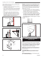
Attic Insulation Shield
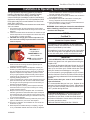
1 + 2 + 3 + 4 = 270°
1
1
2
2
3
Upper Floor
3
4
11”
(279mm)
4
11”
(279mm)
Ceiling Installation
Joist
FP1179
Firestop
Spacer
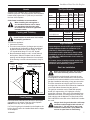
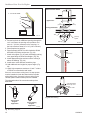
Fig. 24 Maximum elbow usage.
4. Proceed to plumb for additional openings through the
roof. In all cases, the opening must provide a minimum of 1” (25 mm) clearance to the vent pipe, i.e.,
the hole must be at least 9³⁄₈” x 9³⁄₈” (240 x 240 mm).
5. Place fireplace into position.
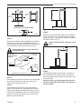
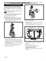
6. Place firestop(s) #7DVFS or Attic Insulation Shield
#7DVAIS into position and secure. (Fig. 26)
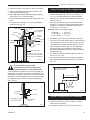
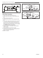
7. Install roof support (Fig. 25) and roof flashing making
sure upper flange is below the shingles. (Fig. 28)
8. Install appropriate pipe sections until the venting is
above the flashing. (Fig. 28)
9. Install storm collar and seal around the pipe.
10. Add additional vent lengths for proper height. (Fig.
28)
11. Apply high temperature sealant to 4” and 7” collars
of vertical vent termination and install.
If there is a room above ceiling level, fire stop spacer
must be installed on both the bottom ad the top side
of the ceiling joists. If an attic is above ceiling level a
7DVAIS (Attic Insulation Shield) must be installed.
The enlarged ends of the vent section always face
downward.
Nails (4)
FP1029
Fig. 26 Place firestop spacer(s) and secure.
FP1029
attic insulation shield
firestop Min.
spacers
(610 mm)
1/28/00 2'djt
FP1185
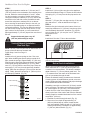
Fig. 27 Minimum termination to roof clearance.
3 #5 Sheet Metal
Screws per Joint
Sealant
Storm Collar
TWL101a
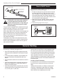
Fig. 28 Roof flashing.
Typical Roof
Support
Application
Fig. 25
16
Typical Ceiling
Support
Application
Venting FP1184
supports.
Typical roof/ceiling
support apps.
TWL101a
Twist Lock Pipe
2/8/99 djt
FP1184
10009459