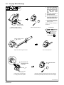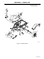
1
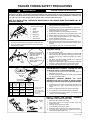
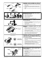
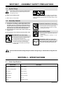
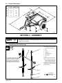
OM-699 189 553C May 2000 Description Two-Wheel Trailer For Small EngineDriven Welding Generators HWY-210 Visit our website at www.MillerWelds.com From Miller to You Thank you and congratulations on choosing Miller. Now you can get the job done and get it done right. We know you don’t have time to do it any other way. That’s why when Niels Miller first started building arc welders in 1929, he made sure his products offered long-lasting value and superior quality. Like you, his customers couldn’t afford anything less. Miller products had to be more than the best they could be. They had to be the best you could buy. Today, the people that build and sell Miller products continue the tradition. They’re just as committed to providing equipment and service that meets the high standards of quality and value established in 1929. This Owner’s Manual is designed to help you get the most out of your Miller products. Please take time to read the Safety precautions. They will help you protect yourself against potential hazards on the worksite. We’ve made installation and operation quick and easy. With Miller you can count on years of reliable service with proper maintenance. And if for some reason the unit needs repair, there’s a Troubleshooting section that will help you Miller is the first welding figure out what the problem is. The parts list equipment manufacturer in will then help you to decide which exact part the U.S.A. to be registered to the ISO 9001 Quality System you may need to fix the problem. Warranty and Standard. service information for your particular model are also provided. Miller Electric manufactures a full line of welders and welding related equipment. For information on other quality Miller products, contact your local Miller distributor to receive the latest full line catalog or individual catalog sheets. To locate your nearest distributor or service agency call 1-800-4-A-Miller, or visit us at www.MillerWelds.com on the web. Working as hard as you do – every power source from Miller is backed by the most hassle-free warranty in the business. Miller offers a Technical Manual which provides more detailed service and parts information for your unit. To obtain a Technical Manual, contact your local distributor. Your distributor can also supply you with Welding Process Manuals such as SMAW, GTAW, GMAW, and GMAW-P. TRAILER TOWING SAFETY PRECAUTIONS TRAILER TOWING can be hazardous. WARNING In trailer towing, as in most driving situations, exposure to certain hazards occurs. Trailer towing is safe when precautions are taken. The following safety information is only a summary of the more complete information found in the Safety Standards listed at the end of these precautions. Read and follow all Safety Standards. In addition, the end user must check and comply with all federal, state, and local laws before use. HAVE ALL INSTALLATION, OPERATION, MAINTENANCE, AND REPAIR WORK PERFORMED ONLY BY QUALIFIED PEOPLE. 3 1 2 1 3 5 7 3 6 4 Coupler Hitch is on towing vehicle. 2 Tongue 3 Lights 4 Wheels And Bearings 5 Rating Plate 6 Jack Stand 7 Safety Chains 1. Use a towing vehicle prepared and capable of handling the load. 2. Towing any trailer requires special awareness because of the changed driving situation. 3. When towing, it takes longer to start, stop, and pass – use training and practice to avoid accidents. 4. Turning and backing up present new problems – plan ahead. 5. Require each driver to be fully trained and experienced in trailer towing before going out on the road. 6. Holes are provided for mounting weld/power generator. 7. Be sure trailer is fully prepared and connected to towing vehicle. 8. Observe maximum speed of 45 mph (72 kph) when towing. 9. Do not modify or change the trailer in any way – changes void the warranty. Read Owner’s Manual. 10. Use only genuine factory parts as replacements. 11. Adjust load on trailer so tongue weight is approximately 10% of the gross trailer weight and center load side-to-side to reduce fishtailing. 12. Tighten all parts, bolts, nuts, and mounting hardware. OVERLOADING can cause serious injury or equipment damage. Rating Plate GVWR – Gross Vehicle Weight Rating (Maximum Total Trailer Weight Including Its Load) GAWR – Gross Axle Weight Rating VIN NO – Vehicle Identification Number 1. Do not overload the trailer. 2. The Gross Vehicle Weight Rating (GVWR) is the maximum total trailer weight with the engine driven welding generator and all equipment, such as tools, cables, and shielding gas cylinder, installed. 3. The Gross Axle Weight Rating (GAWR) is the maximum load-bearing capacity of the axle(s). 4. Weigh trailer – adjust weight by removing accessory equipment if necessary – call local authorities for nearest scale location. 5. Use gross trailer weight to select a proper towing vehicle. UNCONTROLLED TILTING OF TRAILER can result in personal injury or equipment damage. 1. Install generator according to Owner’s Manual with engine end toward hitch end of trailer. Tongue – Level 2. Distribute weight so that trailer tongue weight is approximately 10% of the gross trailer weight. Bathroom Scale Pipe Approximately 10% Of GTW Trailer Gross Vehicle And Weight Rating Gross Trailer2 Weight GTW Coupler GVWR Class 1 lb (kg) lb (kg) Maximum Tongue Weight3 lb (kg) 1 Up to 2000 (Up to 910) 1000 (455) 2000 (910) 100 (45) 200 (90) 2 2000 to 3500 (910 to 1590) 2000 (910) 3500 (1590) 200 (90) 350 (158) 3 3500 to 5000 (1590 to 2270) 3500 (1590) INCORRECT TONGUE WEIGHT can cause fishtailing and loss of control of towing vehicle resulting in serious injury and equipment damage. Board 350 (158) 3. Tongue weight is the amount of trailer weight that rests on the towing vehicle hitch – that is, the downward pressure on the coupler. 1 Information From SAE J684 May 1987 4. Remove or adjust trailer load to get correct tongue weight. 2 Gross Trailer Weight (Actual Loaded Weight) 5. Do not let tongue weight exceed coupler and hitch rating. 3 10% Of GTW Recommended 6. Use slower speeds when towing a trailer – never above 45 mph (72 km/h) – to prevent fishtailing. SAFETY CHAINS CAN PREVENT RUNAWAY TRAILER in case hitch/coupler fails. Bottom View Side View 1. Always use safety chains when towing. 2. Cross safety chains under coupling to prevent tongue from dropping to ground. 3. Allow only enough slack for tight turns. 4. Do not let safety chains drag on ground. 5. Twist safety chains equally from hook ends to take up slack. 6. Use safety chains rated equal to or greater than twice the maximum gross trailer weight rating. safety_trailer 2/98 INCORRECT SIZE OR RATING OF HITCH can cause trailer to break loose from towing vehicle. Couplers Clevis OR Trailer Tongue Lunette Eye 1. Be sure towing vehicle hitch is correct type, size, and rating to match coupler. 2. Be sure the hitch is properly installed onto towing vehicle. 3. On optional ball couplers, always insert hitch safety pin before towing. 4. Make sure hitch and ball are properly sized and match each other. Ball Safety Pin WHEELS MUST BE CHOCKED when trailer is uncoupled from vehicle. 1. 2. 3. 4. 5. Chock in direction of grade. Position chock snugly behind tire. Place chock square to the tire. Tap chock into place. For added protection, chock both sides of tire. UNEXPECTED TILTING OF TRAILER can cause injury and damage. 1. When trailer is uncoupled from towing vehicle, use jack on front and block rear to prevent tilting. 2. Use proper blocks that are large enough and able to support the necessary weight. 3. Always chock the wheels when uncoupled. INCORRECTLY WORKING LIGHTS can cause accidents. Tail, Stop, And Turn Lights 1. State and Federal regulations require trailers used on highways to have tail, stop, turn, and side marker lights. 2. Lights are not required for trailers designed for off-road use only. 3. Check all lights and connectors for proper installation and operation before using the trailer. 4. Check condition of wiring harness leads, plugs, and connections regularly. Repair or replace damaged parts or wires. Side Marker Lights 5. Replace any broken lenses, reflectors, or bulbs. INCORRECT TORQUE on lug nuts or INCORRECT TIRE PRESSURE or BEARING MAINTENANCE can cause loss of control resulting in serious injury and equipment damage. Torquing Sequence 1 3 4 4-Hole Wheels – Torque Lug Nuts To 60 ft-lbs (81 N·m) 2 1 Lug Nuts Wheel Bearings Inside Hub 3 5 Self-Actuating Hydraulic Brake System Breakaway Cable Surge-Type Coupler Bracket safety_trailer 2/98 4 5-Hole Wheels – Torque Lug Nuts 2 To 70 ft-lbs (95 N·m) Brake Fluid Reservoir 1. Recheck lug nut torque after first 50 miles (80 km) and once each year or every 12,000 miles (19,500 km) thereafter, whichever comes first. 2. When checking lug nuts, keep them clean, dry, and unlubricated. 3. Check and repack wheel bearings once each year or every 12,000 miles (19,500 km), whichever comes first. 4. Maintain correct tire pressure according to sidewall data on tire – underinflation is the most common cause of tire trouble. 5. Check tires for wear every six months. 6. Use only replacement tires of the same size, rating, and capacity. INOPERATIVE SURGE-TYPE BRAKES OR WRONG BREAKAWAY CABLE CONNECTION can cause accidents. 1. Check brake fluid level before use. 2. Do not use sway control devices – keep coupler free to telescope during braking. 3. Always connect breakaway cable to towing vehicle – be sure it has a direct free pull. 4. Do not wrap cable around safety chains, tongue, wiring, or any other parts. 5. The breakaway cable automatically applies the trailer brakes if separation occurs. LOOSE OR INCORRECT HARDWARE AND FASTENERS can cause injury and damage. Grade Marks. Manufacturer’s Identification Mark 1. Periodically double-check all nuts and bolts for tightness and condition. 2. If necessary, always replace any fastener with one of equal size, grade, and type. 3. Be sure the grade marks on replacement fastener match the original bolt. The manufacture’s identification mark is not critical and does not matter for the replacement fastener. PRE-TOWING CHECKLIST Check gross trailer weight, tongue weight, and total weight distribution – do not overload this trailer. Check that the correct hitch is properly installed on towing vehicle. When coupling, check that coupler locking device (safety pin), safety chains, and breakaway cable (if applicable) are properly connected. Check that tires are properly inflated and that wheel nuts are properly torqued. If applicable, check that all lights are working properly. PRINCIPAL SAFETY STANDARDS Trailer & Camper Safety, Publication # DOT HS-802586, from U.S. Department of Transportation, National Highway Traffic Safety Administration, Washington, D.C. 20590 SAE Handbook. 1996. Volume 4. On-Highway Vehicles and Off-Highway Machinery, from Society of Automotive Engineers, Inc., 400 Commonwealth Drive, Warrendale, PA 15096-0001. Safety and Health Standards, OSHA 49 CFR 200 to 999, from Superintendent of Documents, U.S. Government Printing Office, Washington, D.C. 20402 REPORTING SAFETY DEFECTS If you believe that your vehicle has a defect which could cause a crash or could cause injury or death, you should immediately inform the National Highway Traffic Safety Administration (NHTSA) in addition to notifying MILLER Electric Mfg. Co. If NHTSA receives similar complaints, it may open an investigation, and if it finds that a safety defect exists in a group of vehicles, it may order a recall and remedy campaign. However, NHTSA cannot become involved in individual problems between you, your dealer, or MILLER Electric Mfg. Co. To contact NHTSA, you may either call the Auto Safety Hotline toll-free at 1-800-424-9393 (or 366-0123 in Washington, D.C. area) or write to: NHTSA, U.S. Department of Transportation, Washington D.C. 20590. You can also obtain other information about motor vehicle safety from the Hotline. mod11.1 8/94 safety_trailer 2/98 SECTION 1 – ASSEMBLY SAFETY PRECAUTIONS trail_safety 2/98 1-1. Symbol Usage Means Warning! Watch Out! There are possible hazards with this procedure! The possible hazards are shown in the adjoining symbols. This group of symbols means Warning! Watch Out! possible FALLING EQUIPMENT and TILTING OF TRAILER hazards. Consult symbols and related instructions below for necessary actions to avoid the hazards. Y Marks a special safety message. . Means “Note”; not safety related. 1-2. Assembly Hazards Y The symbols shown below are used throughout this manual to call attention to and identify possible hazards. When you see the symbol, watch out, and follow the related instructions to avoid the hazard.The safety information given below is only a summary of the more complete safety information found in the Safety Standards. Read and follow all Safety Standards. Y Only qualified persons should install, operate, maintain, and repair this unit. Y During operation, keep everybody, especially children, away. FALLING UNIT can cause injury. D Use equipment and blocks of adequate capacity and size to lift and support unit. D If using lift forks to move unit or parts, be sure forks are long enough to extend beyond opposite side of unit or parts to prevent tipping. D Have two people of adequate physical strength lift trailer parts. TILTING OF TRAILER can cause injury. D Use tongue jack or blocks to support weight. D Properly install welding generator onto trailer according to instructions. READ INSTRUCTIONS. D Use only genuine replacement parts from manufacturer. D Perform maintenance according to this manual. FLYING METAL, DIRT can injure eyes. D Wear approved safety glasses with side shields when assembling and maintaining trailer. Read and follow all trailer towing Safety Precautions at beginning of manual before using this trailer. SECTION 2 – SPECIFICATIONS 2-1. Trailer Specifications Specification Description Gross Axle Weight Rating 1500 lb (680 kg) Gross Vehicle Weight Rating 1610 lb (730 kg) Net Payload 1350 lb (612 kg) Road Clearance 6-1/2 in (165 mm) Height Of Bed 18-1/2 in (470 mm) Standard Tires 4.8 – 12 Weight Net: 265 lb (120 kg) OM-699 Page 1 2-2. Overall Dimensions Inches Millimeters A 18-1/2 470 B 10-1/4 260 C 36-3/4 933 D 59 1499 E 94 2388 D C E B A ST-802 067-A SECTION 3 – ASSEMBLY NOTE All directions are given as facing the towing vehicle. The word “front” means the hitch end of the trailer. 3-1. Assembling Axle And Springs . Use hardware in orange bag to assemble axle and springs. 1 2 The axle has a slight camber (arch) to help the tires wear properly when the trailer is loaded. With no load on the trailer the tires appear to tilt outward. When the trailer is loaded, the tires straighten out and wear evenly. 1 Axle 2 U-Bolt 3 Leaf Spring 4 Spring Center Bolt 5 Spring Plate 6 Nut Assemble components as shown. . Be sure the spring eyes point up and the spring center bolt is in the hole of the spring plate. 3 Cross-tighten hardware so plate is installed evenly. Torque hardware to 55 ft lb (74 N.m). 4 5 Tools Needed: 3/4 in 6 OM-699 Page 2 802 529 3-2. Assembling Trailer Tools Needed: 13/16, 7/8, 9/16 in 13 13/16 in 11 10 12 9 3 1 12 2 4 14 8 5 6 7 Ref. ST-802 073-A Y Use adequate blocks or lifting device to support frame while installing parts. Attach axle assembly to brackets on frame using 9/16 inch hardware. Tighten hardware to 50 ft lb (67 N.m) maximum. When jack is not needed, pull pin and rotate jack to horizontal position. 9 Fender Bracket . Use hardware in red bag to mount axle . Do not overtighten spring and shackle . Install bracket with top angling in (toward and wheels. Use hardware in green bag to mount fenders. 1 Shackle Arm 2 Spring Attach shackle arms to springs using 9/16 inch hardware. Tighten hardware to 50 ft lb (67 N.m) maximum. . Do not overtighten shackle arm hardware. Parts must rotate freely. 3 Shackle Bracket . Install axle assembly with axle label facing front or rear of trailer. arm hardware. Parts must rotate freely. 4 Wheel 5 Hub 6 Lug Nut Install wheels on hubs. Tighten lug nuts to 70 ft lb (95 N.m). Block wheels. 7 Jack 8 Snap Ring Slide jack over collar. Use snap ring pliers to secure jack with snap ring. Pull pin and rotate jack to vertical position. Pin locks jack in place. Turn handle to raise or lower trailer. fender). 10 Fender 11 Light Bracket 12 Star Washer Mount fender brackets, light brackets, and fenders on trailer using supplied 3/8 in hardware. Be sure to install star washers between light brackets and fenders, and between fender brackets and frame. 13 Cable Tree (Optional) 14 Cable Tree Mounting Bracket Mount cable tree on trailer using supplied hardware. OM-699 Page 3 3-3. Installing Hitch And Safety Chains 3 2 7 4 6 5 Tools Needed: 1 5/8, 3/4 in 11/16, 3/4 in ST-802 067-B / Ref. ST-802 067-B Y Use adequate blocks or lifting device to support frame while installing parts. Y Support trailer with jack. Block wheels. 3 Chain Bracket Attach chain to bracket with 7/16 in hardware. Tighten hardware to 31 ft lb (40 N.m). 4 Ball Hitch . Use hardware in blue bag to mount 5 Safety Pin 1 Block wheels. Attach hitch to tongue using 1/2 in hardware (2 required). Make sure bolt is installed horizontally as shown. 2 Tighten hardware to 75 ft lb (102 N.m). safety chain. Wheel Block Safety Chain OM-699 Page 4 Set trailer onto towing ball and push lever down. Insert safety pin through hole in lever to secure hitch. 6 Clevis Hitch (Optional) Attach bars to top and bottom of tongue using 1/2-13 x 4-1/2 in hardware (2 required). 7 Lunette Eye Hitch (Optional) Attach lunette eye to top of tongue using 1/2-13 x 3-1/2 in hardware (2 required). Cross safety chains under tongue and attach to towing vehicle. 3-4. Installing Light Kit 3 5 2 7 Tools Needed: 4 1 7/16, 9/16 in 5 6 1/4 in Wiring Connections: Sidelight Right Stop/ Signal Lamps (Green) Left Stop/ To Vehicle Signal Lamps (Yellow) Green Lead Short Lead RIGHT To Trailer Brown Lead Taillights Tab Connectors Taillights (Brown) Yellow Lead Ground (White) LEFT White Ground Lead (Ground To Trailer Frame) Short Lead Sidelight Brown Lead ST-802 074-A Y Support trailer with jack. Block wheels. . Use hardware in green bag to install lights. . Use supplied wire to route harness leads through trailer frame. 1 Wiring Harness White Ground Lead Strip insulation from end of white ground lead and crimp on supplied ring terminal. Attach ground lead ring terminal to chain bracket using 3/4 in sheet metal screw. Locate holes for routing wire near each taillight. Route brown and green leads inside of right frame to exit hole. Route brown and yellow leads inside left side. 2 Grommet Route leads through grommets. Install grommets in holes in trailer frame. Strip 1/2 in (12.7 mm) insulation from ends of brown, green, and yellow leads. 3 Taillight Splice sidelight short lead to wiring harness brown lead using supplied tab connector (see Section 3-5). Mount sidelight on frame using supplied selftapping screws. Install other sidelight the same way. Insert stripped end of green lead into right taillight hole marked STOP & TURN (GREEN). Insert stripped end of yellow lead into left taillight hole marked STOP & TURN (YELLOW). Insert stripped end of brown leads into TAIL (BROWN) holes in each light. 5 Mount lights on brackets using supplied 1/4 nuts. 4 Sidelight Install cable tie in 1/4 in (6 mm) hole in bottom of tongue. Use tie to secure harness and sleeving. Pull a small length of brown lead thru hole in side of trailer. Sleeving Install sleeving on taillight and harness plug electrical leads. 6 7 Hanging Cable Tie End Cap Install caps in end of trailer. OM-699 Page 5 3-5. Installing Wiring Harness Tab Connectors NOTE 1 Disconnect vehicle wiring harness plug from trailer wiring connector before beginning installation. Use wiring harness tab connectors only with insulated wires. 3 1 Connector 2 Run Wire 3 Tap Wire Place unstripped run wire in slotted channel. Insert unstripped tap wire into other channel until it hits internal stop. 4 4 Contact 5 9 Inch Linemans Pliers Use pliers to push contact down flush with top of connector. 5 2 Close top cover. Ref. S-0448 3-6. Installing Welding Generator Y Use equipment of adequate capacity to lift the generator. Y Support front of trailer with jack. Support rear of trailer with blocks. Block wheels. Y If trailer is not installed on vehicle, use trailer jack to obtain desired height and to support tongue weight while installing welding generator. 1 1 Y Install welding generator on trailer with engine end toward hitch end of trailer. Y Distribute weight so trailer tongue weight is approximately 10% of gross trailer weight. . Use hardware in yellow bag to mount welding generator. . The axle has a slight camber (arch) to help the tires wear properly when the trailer is loaded. With no load on the trailer the tires appear to tilt outward. When the trailer is loaded, the tires straighten out and wear evenly. 1 Crossmember Mounting Holes Use supplied hardware to install generator so front panel faces rear. Move crossmembers to correct position on trailer frame so mounting holes align with welding generator holes. Crossmembers should be adjusted so tongue weight is 10 – 15% of gross trailer weight. Tighten crossmembers and secure generator. Tools Needed: 1/2, 9/16 in ST-802 067-B OM-699 Page 6 3-7. Maintenance NOTE Do not use trailer if any part is damaged or not working properly. When performing maintenance, check trailer for worn, damaged, or non-working parts. Check for free rotation of assemblies mounted on bushings or bearings. Y Support trailer with jack. Block wheels. Y Do not put any body part under trailer while lifting or performing maintenance. Once a year, lubricate all moving parts on trailer with SAE 20W oil. Lubricate more often if trailer is exposed to elements or subject to frequent off-road use. 1 Wheel Bearings Every 12,000 miles, check wheel bearings. Repack bearings if necessary using a good quality lithiumbased extreme pressure grease. When reinstalling wheels, be sure wheel nuts are properly tightened (see Trailer Towing Safety Precautions at beginning of manual). Replace trailer hardware only with SAE hardware of same grade, type and size as originally installed. 1 Tools Needed: 13/16, 1-1/2 in ST-802 075-B OM-699 Page 7 3-8. Torquing Wheel Bearings Y Loss of control hazard. To prevent injury and damage, check and repack wheel bearings once a year or every 12,000 miles (19,500 km), whichever comes first. Y Use proper equipment to lift and support unit. Y Do not put any body part under trailer while lifting or performing maintenance. . Torque wheel bearings whenever hub nut is removed or hub is too loose. Repack bearings according to Section 3-7. 0.01 in (0.2 mm) endplay maximum Check hub endplay. If loose, remove wheel and go to next step. Remove cap and cotter pin. Tools Needed: 13/16, 1-1/2 in Torque to 12 ft lb (16 N·m) Torque nut while turning hub forward. Y Do not loosen nut more than 1/8 turn in this step. Further loosen nut until first slot in nut aligns with hole in spindle. Turn nut until “just loose.” Y Pin must not rub on cap. Install new cotter pin and bend ends around nut. Install cap. Install wheel (See Safety Precautions) and recheck endplay. Ref. ST-800 441-B OM-699 Page 8 SECTION 4 – PARTS LIST . Hardware is common and not available unless listed. 5 4 1 3 2 6 7 10 12 8 14 11 15 9 5 13 16 17 ST-802 076-B Figure 4-1. Complete Assembly OM-699 Page 9 Item No. Part No. Description Quantity Figure 4-1. Complete Assembly . . . 1 . . ♦043 826 . . CABLE TREE (includes mounting hardware) . . . . . . . . . . . . . . . . . . . . . . . . . . . . . . . . . . . . . 2 . . . 189 594 . . FENDER . . . . . . . . . . . . . . . . . . . . . . . . . . . . . . . . . . . . . . . . . . . . . . . . . . . . . . . . . . . . . . . . . . . . . . . . . . 189 581 . . FENDER, hardware kit . . . . . . . . . . . . . . . . . . . . . . . . . . . . . . . . . . . . . . . . . . . . . . . . . . . . . . . . 3 . . . 189 595 . . FENDER, mtg bracket . . . . . . . . . . . . . . . . . . . . . . . . . . . . . . . . . . . . . . . . . . . . . . . . . . . . . . . . . 4 . . . 189 582 . . GUARD, light . . . . . . . . . . . . . . . . . . . . . . . . . . . . . . . . . . . . . . . . . . . . . . . . . . . . . . . . . . . . . . . . 5 . . . 189 577 . . LIGHT KIT (includes wiring harness) . . . . . . . . . . . . . . . . . . . . . . . . . . . . . . . . . . . . . . . . . . . . 6 . . . 189 597 . . SLIDE, crossmember . . . . . . . . . . . . . . . . . . . . . . . . . . . . . . . . . . . . . . . . . . . . . . . . . . . . . . . . . 7 . . . 189 596 . . DECK . . . . . . . . . . . . . . . . . . . . . . . . . . . . . . . . . . . . . . . . . . . . . . . . . . . . . . . . . . . . . . . . . . . . . . . . . . . . . 189 693 . . MOUNTING HARDWARE KIT . . . . . . . . . . . . . . . . . . . . . . . . . . . . . . . . . . . . . . . . . . . . . . . . . . 8 . . . 189 591 . . TIRE, 4.80-12 (includes rim) . . . . . . . . . . . . . . . . . . . . . . . . . . . . . . . . . . . . . . . . . . . . . . . . . . . 9 . . . 189 593 . . HUB, axle #3 (consisting of) . . . . . . . . . . . . . . . . . . . . . . . . . . . . . . . . . . . . . . . . . . . . . . . . . . . . . . . . . . 091 991 . . . . CAP, grease . . . . . . . . . . . . . . . . . . . . . . . . . . . . . . . . . . . . . . . . . . . . . . . . . . . . . . . . . . . . . . . . . . . . . . 190 760 . . . . SEAL, grease . . . . . . . . . . . . . . . . . . . . . . . . . . . . . . . . . . . . . . . . . . . . . . . . . . . . . . . . . . . . . . . . . . . . 190 762 . . . . BEARING . . . . . . . . . . . . . . . . . . . . . . . . . . . . . . . . . . . . . . . . . . . . . . . . . . . . . . . . . . . . . . . . . . . . . . . . 190 761 . . . . RACE, bearing . . . . . . . . . . . . . . . . . . . . . . . . . . . . . . . . . . . . . . . . . . . . . . . . . . . . . . . . . . . . . . . . . . . 190 759 . . . . HOUSING, hub axle . . . . . . . . . . . . . . . . . . . . . . . . . . . . . . . . . . . . . . . . . . . . . . . . . . . . . . . . . . . . . . . 167 787 . . KIT, bearing (for one wheel – includes bearings, cups, grease cap, . . . . . . . . . . . . . . . . . . . . grease seal, and key) . . . . . . . . . . . . . . . . . . . . . . . . . . . . . . . . . . . . . . . . . . . . . . . . . . . . . . . . . 10 . . . 189 592 . . AXLE, #3 (includes hub – does not include leaf springs and hardware) . . . . . . . . . . . . . . . . . . . . . 189 579 . . AXLE, parts bag (includes red bag hardware) . . . . . . . . . . . . . . . . . . . . . . . . . . . . . . . . . . . . . 11 . . . 198 546 . . SPRING, leaf (includes the following) . . . . . . . . . . . . . . . . . . . . . . . . . . . . . . . . . . . . . . . . . . . . 12 . . . 088 870 . . . . BUSHING, nylon . . . . . . . . . . . . . . . . . . . . . . . . . . . . . . . . . . . . . . . . . . . . . . . . . . . . . . . . . . . . 13 . . . 189 586 . . JACK, screw w/pad . . . . . . . . . . . . . . . . . . . . . . . . . . . . . . . . . . . . . . . . . . . . . . . . . . . . . . . . . . . 14 . . . 189 587 . . JACK, ret ring . . . . . . . . . . . . . . . . . . . . . . . . . . . . . . . . . . . . . . . . . . . . . . . . . . . . . . . . . . . . . . . . 15 . . . 199 860 . . CHAIN, safety . . . . . . . . . . . . . . . . . . . . . . . . . . . . . . . . . . . . . . . . . . . . . . . . . . . . . . . . . . . . . . . . 16 . . . 189 585 . . HITCH, ball 2.000 . . . . . . . . . . . . . . . . . . . . . . . . . . . . . . . . . . . . . . . . . . . . . . . . . . . . . . . . . . . . 16 . . ♦043 824 . . LUNETTE EYE . . . . . . . . . . . . . . . . . . . . . . . . . . . . . . . . . . . . . . . . . . . . . . . . . . . . . . . . . . . . . . . 16 . . ♦043 825 . . CLEVIS HITCH . . . . . . . . . . . . . . . . . . . . . . . . . . . . . . . . . . . . . . . . . . . . . . . . . . . . . . . . . . . . . . . 17 . . . 191 267 . . HARNESS, trailer (also included in item 5 – light kit) . . . . . . . . . . . . . . . . . . . . . . . . . . . . 1 2 1 2 2 1 2 1 1 2 2 1 2 2 2 1 1 1 1 2 2 1 1 1 1 1 1 1 ♦OPTIONAL To maintain the factory original performance of your equipment, use only Manufacturer’s Suggested Replacement Parts. Model and serial number required when ordering parts from your local distributor. OM-699 Page 10 Effective January 1, 2000 (Equipment with a serial number preface of “LA” or newer) This limited warranty supersedes all previous Miller warranties and is exclusive with no other guarantees or warranties expressed or implied. Warranty Questions? Call 1-800-4-A-MILLER for your local Miller distributor. Your distributor also gives you ... Service You always get the fast, reliable response you need. Most replacement parts can be in your hands in 24 hours. Support Need fast answers to the tough welding questions? Contact your distributor. The expertise of the distributor and Miller is there to help you, every step of the way. * LIMITED WARRANTY – Subject to the terms and conditions below, Miller Electric Mfg. Co., Appleton, Wisconsin, warrants to its original retail purchaser that new Miller equipment sold after the effective date of this limited warranty is free of defects in material and workmanship at the time it is shipped by Miller. THIS WARRANTY IS EXPRESSLY IN LIEU OF ALL OTHER WARRANTIES, EXPRESS OR IMPLIED, INCLUDING THE WARRANTIES OF MERCHANTABILITY AND FITNESS. Within the warranty periods listed below, Miller will repair or replace any warranted parts or components that fail due to such defects in material or workmanship. Miller must be notified in writing within thirty (30) days of such defect or failure, at which time Miller will provide instructions on the warranty claim procedures to be followed. Miller shall honor warranty claims on warranted equipment listed below in the event of such a failure within the warranty time periods. All warranty time periods start on the date that the equipment was delivered to the original retail purchaser, or one year after the equipment is sent to a North American distributor or eighteen months after the equipment is sent to an International distributor. 1. 5 Years Parts – 3 Years Labor * * 2. 3 Years — Parts and Labor * * * * * * 3. Original main power rectifiers Inverters (input and output rectifiers only) Transformer/Rectifier Power Sources Plasma Arc Cutting Power Sources Semi-Automatic and Automatic Wire Feeders Inverter Power Supplies Intellitig Engine Driven Welding Generators (NOTE: Engines are warranted separately by the engine manufacturer.) 1 Year — Parts and Labor * * * * * * * * * * * * * * * * * DS-2 Wire Feeder Motor Driven Guns (w/exception of Spoolmate 185 & Spoolmate 250) Process Controllers Positioners and Controllers Automatic Motion Devices RFCS Foot Controls Induction Heating Power Sources Water Coolant Systems HF Units Grids Maxstar 140 Spot Welders Load Banks Miller Cyclomatic Equipment Running Gear/Trailers Plasma Cutting Torches (except APT & SAF Models) Field Options (NOTE: Field options are covered under True Blue for the remaining warranty period of the product they are installed in, or for a minimum of one year — whichever is greater.) 4. 6 Months — Batteries 5. 90 Days — Parts * * MIG Guns/TIG Torches Induction Heating Coils and Blankets * * * * * APT, ZIPCUT & PLAZCUT Model Plasma Cutting Torches Remote Controls Accessory Kits Replacement Parts (No labor) Spoolmate 185 & Spoolmate 250 Canvas Covers Miller’s True Blue Limited Warranty shall not apply to: 1. Consumable components; such as contact tips, cutting nozzles, contactors, brushes, slip rings, relays or parts that fail due to normal wear. 2. Items furnished by Miller, but manufactured by others, such as engines or trade accessories. These items are covered by the manufacturer’s warranty, if any. 3. Equipment that has been modified by any party other than Miller, or equipment that has been improperly installed, improperly operated or misused based upon industry standards, or equipment which has not had reasonable and necessary maintenance, or equipment which has been used for operation outside of the specifications for the equipment. MILLER PRODUCTS ARE INTENDED FOR PURCHASE AND USE BY COMMERCIAL/INDUSTRIAL USERS AND PERSONS TRAINED AND EXPERIENCED IN THE USE AND MAINTENANCE OF WELDING EQUIPMENT. In the event of a warranty claim covered by this warranty, the exclusive remedies shall be, at Miller’s option: (1) repair; or (2) replacement; or, where authorized in writing by Miller in appropriate cases, (3) the reasonable cost of repair or replacement at an authorized Miller service station; or (4) payment of or credit for the purchase price (less reasonable depreciation based upon actual use) upon return of the goods at customer’s risk and expense. Miller’s option of repair or replacement will be F.O.B., Factory at Appleton, Wisconsin, or F.O.B. at a Miller authorized service facility as determined by Miller. Therefore no compensation or reimbursement for transportation costs of any kind will be allowed. TO THE EXTENT PERMITTED BY LAW, THE REMEDIES PROVIDED HEREIN ARE THE SOLE AND EXCLUSIVE REMEDIES. IN NO EVENT SHALL MILLER BE LIABLE FOR DIRECT, INDIRECT, SPECIAL, INCIDENTAL OR CONSEQUENTIAL DAMAGES (INCLUDING LOSS OF PROFIT), WHETHER BASED ON CONTRACT, TORT OR ANY OTHER LEGAL THEORY. ANY EXPRESS WARRANTY NOT PROVIDED HEREIN AND ANY IMPLIED WARRANTY, GUARANTY OR REPRESENTATION AS TO PERFORMANCE, AND ANY REMEDY FOR BREACH OF CONTRACT TORT OR ANY OTHER LEGAL THEORY WHICH, BUT FOR THIS PROVISION, MIGHT ARISE BY IMPLICATION, OPERATION OF LAW, CUSTOM OF TRADE OR COURSE OF DEALING, INCLUDING ANY IMPLIED WARRANTY OF MERCHANTABILITY OR FITNESS FOR PARTICULAR PURPOSE, WITH RESPECT TO ANY AND ALL EQUIPMENT FURNISHED BY MILLER IS EXCLUDED AND DISCLAIMED BY MILLER. Some states in the U.S.A. do not allow limitations of how long an implied warranty lasts, or the exclusion of incidental, indirect, special or consequential damages, so the above limitation or exclusion may not apply to you. This warranty provides specific legal rights, and other rights may be available, but may vary from state to state. In Canada, legislation in some provinces provides for certain additional warranties or remedies other than as stated herein, and to the extent that they may not be waived, the limitations and exclusions set out above may not apply. This Limited Warranty provides specific legal rights, and other rights may be available, but may vary from province to province. miller_warr 7/00 Owner’s Record Please complete and retain with your personal records. Model Name Serial/Style Number Purchase Date (Date which equipment was delivered to original customer.) Distributor Address City State Zip For Service Call 1-800-4-A-Miller or see our website at www.MillerWelds.com to locate a DISTRIBUTOR or SERVICE AGENCY near you. Always provide Model Name and Serial/Style Number. Contact your Distributor for: Welding Supplies and Consumables Options and Accessories Personal Safety Equipment Service and Repair Miller Electric Mfg. Co. An Illinois Tool Works Company 1635 West Spencer Street Appleton, WI 54914 USA Replacement Parts Training (Schools, Videos, Books) International Headquarters–USA USA Phone: 920-735-4505 Auto-Attended USA & Canada FAX: 920-735-4134 International FAX: 920-735-4125 Technical Manuals (Servicing Information and Parts) Circuit Diagrams European Headquarters – United Kingdom Phone: 44 (0) 1204-593493 FAX: 44 (0) 1204-598066 Welding Process Handbooks www.MillerWelds.com Contact the Delivering Carrier for: File a claim for loss or damage during shipment. For assistance in filing or settling claims, contact your distributor and/or equipment manufacturer’s Transportation Department. PRINTED IN USA 2000 Miller Electric Mfg. Co. 6/00