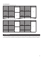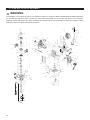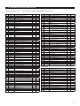
1
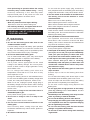
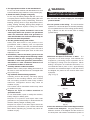
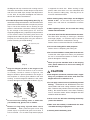
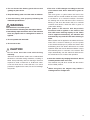
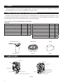
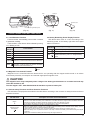
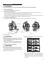
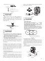
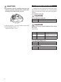
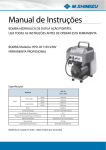
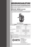
PORTABLE MAGNETIC DRILLING MACHINE
Read this manual carefully before operating your Nitto Kohki
Portable Magnetic Drilling Machine. Keep this manual with
your machine. All users of the Nitto Kohki Portable Magnetic
Drilling Machine must read this manual.
ATRA ACE Model CLA-2720
Professional Tool
For One-Touch Type Annular Cutter Only
(Side-Lock Type Annular Cutter cannot be used.)
Specifications
Model
Battery Pack
No-load Speed
JETBROACH
One-touch type
Hole Capacity
Hi-BROACH
One-touch type
Magnet Dimension
Magnet Holding Power
Weight
CHARGER
Model
Input voltage
Charging time
Weight
CLA-2720
DC 18 V (Li-ion) MODEL :NBL18006
430 min-1
Hole Diameter :
: 12 to 17 mm dia. (Max.Plate thickness:12 mm)
: 17.5 to 27 mm dia. (Max.Plate thickness:20 mm)
Hole Diameter :
: 12 to 15 mm dia. (Max.Plate thickness:12 mm)
: 16 to 27 mm dia. (Max.Plate thickness:20 mm)
65 mm x 126 mm
5500 N
7 kg(Handle Ass'y and Battery Pack are included.)
NC14435
220 - 240 V AC
90 min
0.6 kg(Cord is not included.)
The specifications and configurations contained in this document are subject to
change without prior notice due to improvements we are making day in, day out.
Manufactured by :
NITTO KOHKI Co., Ltd.
2-9-4, Nakaikegami, Ota-ku,
Tokyo, 146-8555, Japan
Tel : (81)-3-3755-1111
Fax : (81)-3-3753-8791
E-mail : [email protected]
URL : www.nitto-kohki.co.jp
Keep the manual handy – so you can use it whenever necessary.
Original Instructions
Thank you very much for your
purchase of Nitto Kohki product.
Before using your machine, please
read this manual carefully so that you
may use it properly to get the most
out of it.
Please keep the manual handy - so
you can use it whenever necessary.
・English
:Please ask your dealer or
distributor for instruction manual
in local language(s).
・German
:Bitte fragen Sie lhren Händler
nach eine Betriebsanleitung in
Landessprache.
・French
:S'il vous plait, veuillez demandez
á votre foumisseur de manuel
instruction en langue locale.
・Spanish
:Por favor, cantacte con su
distribuidor para el manual de
instrucciones en español.
・Portuguese :Por favor pessa ao seo agente
ou distribuidor o manual de
instrucces ih linguagen local.
・Italian
:Per Manuale lstruzioni in lingua
locale Vi preghiamo di rivolgervi
al rivenditore o distributore.
・Dutch
:Vraag uw handelaar
om een nederladstalige
gebruiksaanwijzing.
・Swedish
:Be er lokala Åtreförsäljare eller
distributör om manualer pá
svenska.
CONTENTS
page
GENERAL SAFETY RULES ………………………………… 2
POWER TOOL SAFETY ……………………………………… 3
GENERAL SAFETY RULES FOR
CORDLESS MACHINE ……………………………………… 5
ABOUT YOUR NITTO PORTABLE
MAGNETIC DRILLING MACHINE ………………………… 6
1. USAGE …………………………………………………… 9
2. CHECK THE CONTENTS OF THE PACKAGE ……… 9
3. NAME OF PARTS ……………………………………… 9
4. ELECTRONIC CONTROL FUNCTIONS …………… 10
5. CHARGING METHOD ……………………………… 11
6. PREPARATIONS ……………………………………… 12
7. MACHINE OPERATION ……………………………… 16
8. TROUBLESHOOTING ……………………………… 19
9. MAINTENANCE AND INSPECTION ……………… 19
10. ORDERING SERVICE PARTS ……………………… 21
11. RECYCLE ……………………………………………… 22
12. ATRA ACE CLA-2720 ASSEMBLY ………………… 23
13. ATRA ACE CLA-2720 PARTS LIST ………………… 24
PICTOGRAM
Warning: It might be dangerous to operate the power
tool if the instructions supplied are not followed.
Do not allow the main body or the power source to get
wet as it will cause electric shock and leakage.
Using this tool improperly could result in serious injury.
Read the instruction manual before using.
Always wear suitable eye protection.
Always wear suitable hearing protection.
・Danish
:Venligst henvend Dem til den
danske distributør for instructions
manualer.
・Polish
:Prosze pytac swojego dealera
lub dystrybutora o instrukcje
obslugi w jezyku localnym.
・中文
:
Always wear respiratory protective equipment (PPE).
The following Safety notations are used throughout the manual to highlight safety precautions for the user and for
the machine.
DANGER:
Indicates an imminently hazardous situation which, if not avoided by following the
instructions given, will result in death or serious injury.
WARNING:
Indicates a potentially hazardous situation which, if not avoided by following the
instructions given, could result in death or serious injury.
CAUTION:
Indicates a potentially hazardous situation which, if not avoided by following the
instructions given, could result in injury or material damage.
Caution: Important precautions for machine or tool setup, operation and maintenance.
1
GENERAL SAFETY RULES
WARNING
TO OPERATORS
Always Wear Proper Clothing
● Do not wear loose clothing. Loose clothing can
become caught in the drilling machine. This could
cause severe injuries. Be careful that loose clothing
does not come into contact with the machine.
● Wear non-skid footwear. If you lose your footing,
you could contact moving portions of the machine.
This could cause severe injuries. Always wear nonskid footwear and remain balanced when using the
drilling machine.
● Be careful of long hair. Wear a hat or a hair net to
contain long hair. Long hair can become caught in
the drilling machine. This will cause severe injuries.
Be careful that long hair does not come into contact
with the drilling machine.
Always Wear Suitable Eye Protection
● Always wear suitable eye protection. The operation
of your drilling machine will cause flying chips and
particles. These will cause severe eye injuries. You
must always wear suitable eye protection.
● Not all glasses are suitable eye protection. Wear
only suitable eye protection that comply with ANSI
standards. Not all of the lenses are shock resistant.
Ordinary glasses will not provide sufficient eye
protection.
Glasses only for visual correction are not appropriate
to be used as safety glasses.
Always Wear Suitable Hearing Protection
● Always wear suitable hearing protection. The
operation of your drilling machine will cause big sound
occurs. These will cause severe hearing loss injuries.
You must always wear suitable hearing protection.
Always Wear respiratory protective equipment (PPE)
● Always Wear respiratory protective equipment
(PPE) when working in an environment where dust
particles are generated in operation.
Maintain Good Posture
● Always wear non-skid footwear and maintain good
posture. Do not use the drilling machine when you
are tired. Fatigue or loss of balance could cause
you to lose control of the machine. This could cause
severe injuries. Always stay balanced. Always keep
good posture. Stop using the machine if you are tired.
Never Touch the Cutting Tip
● Never touch the moving or cutting tip. Contact with
the moving tip will cause severe injuries. Always
keep all parts of your body away from the cutting tip.
Always keep your hand and clothing away from the
cutting tip.
ABOUT THE WORK AREA
Keep Work Area Clean
● Always keep your work area clean. Cluttered work
areas cause accidents. Always keep clear of other
objects.
● Never use the magnetic drilling machine when it is
wet. Always use the drilling machine in a dry area.
Do not use the drilling machine in the rain. If you
use the machine when it is wet you can get electric
shock. If you use the machine in the rain you can
get an electric shock.
● Always use the drilling machine in a well-lighted
area. Do not use the drilling machine in the dark.
● Avoid all flammable materials. Use of the drilling
machine may cause a spark that could ignite a fire
or an explosion. Never use the machine near any
flammable material.
● Keep away from children. Always keep the drilling
machine away from children. Do not operate drilling
machine when children are present.
BEFORE OPERATION
Make sure that all parts are free from damage
● Make sure that the drilling machine is in good
operating condition. Operation of a damaged
machine could result in severe injuries. If there
is any damage to the machine, do not use the
machine. If there is any damage to the machine,
take it to an authorized Nitto dealer for repair.
● Do not attempt service or repair of the drilling
machine. All service or repair should be done by an
authorized Nitto dealer.
When a failure is observed with the switch, request
for repair to the sales agent where the product was
purchased or your nearest authorized Nitto dealer.
When a damage is observed with the power cord of
the battery charger, request for repair to the sales
agent where the product was purchased or your
nearest authorized Nitto dealer.
Do not use the machine that cannot be started or
stopped by the start switch.
Secure Your Work
● Always secure your work piece. Improperly mounted
work can become loose. This can cause severe
injuries. Always secure all work.
● Always use a vice or a clamp. Do not attempt to hold
any work piece with your hand. Attempting to hold a
work piece with your hand may cause severe injuries.
Always use a vice or clamp to hold the work piece.
● Always secure your drilling machine. Improperly
2
mounted drilling machine can come loose. This can
cause severe injuries. Always secure the drilling
machine.
Avoid Clutter
● Always stay clear of other objects. Cluttered work
areas cause accidents. Always keep a clean work
area and stay away from other objects.
Always Remove Spanner Wrenches and
Adjustment Tools
● Always remove spanner wrenches and adjustment
tools after adjustments have been made to the
drilling machine. Always remove all adjustment tools
before using the drilling machine.
Always Use a Cutter that is Appropriate for Your
Work
● Always use a Cutter that is appropriate for your
work. Avoid heavy-duty work that is the beyond the
capacity of your drilling machine. If the work exceeds
the capacity of your drilling machine, this can cause
accidents and severe injuries. Always use the
drilling machine in accordance with its performance
specifications.
SAFE HANDLING
Never leave the magnetic drilling machine
unattended while it is running. When the machine
is unattended, disconnect the power source. Do
not leave the work area until the machine comes to
a complete stop. Operating the machine while it is
unattended can case accidents that may result in
severe injuries.
● How to store the machine and battery pack.
Store the machine and battery pack at a dry area
under 50°C when not in use. Also, keep the machine
and battery pack out of the reach of children.
● Pay attention when carrying the machine.
Keep your hands away from the start switch when
carrying the machine.
Do not hold parts other than the handle to carry the
machine.
●
MAINTENANCE
Do not take apart or modify your magnetic drilling
machine.
● Do not attempt to disassemble or modify your
magnetic drilling machine.
● Do not modify your magnetic drilling machine.
Modifications can cause accident and severe
injuries.
● All service and repairs must be performed by an
authorized Nitto dealer. Any attempt to service or
repair the machine yourself may result in an accident
and severe injuries.
3
Check all Parts for Damage.
● Always inspect the magnetic drilling machine before
use.
● Always check that the pilot pin and cutter are in
good condition. Use of the machine with worn pilot
pins or worn cutter can cause accidents and severe
injuries.
● Inspect all cutter before you put them on the
magnetic drilling machine.
● Do not operate the magnetic drilling machine with a
damaged or worn cutter. Do not operate the machine
with a damaged or worn pilot pin. Do not operate the
machine with any damaged accessory. Operating
the machine with any damaged part or accessory
can cause accidents and severe injuries. If there is
any damage to the magnetic drilling machine do not
operate the machine. Take it to an authorized Nitto
Dealer for repair.
● Always have the magnetic drilling machine repaired
at an authorized Nitto dealer. Always take the
magnetic drilling machine to an authorized Nitto
dealer for service, repair and replacement parts. If
you cannot locate an authorized Nitto dealer near
you, please contact your sales representative.
● Always use Nitto genuine parts. The use of improper
or non-Nitto parts can cause accidents and severe
injuries. Never use unauthorized parts. To obtain
genuine Nitto parts, contact your sales agent.
● Do not remove any nameplate from your magnetic
drilling machine. Do not remove any labels from
your magnetic drilling machine. If any label or
nameplate is damaged contact your sales agent for
a replacement.
● When a damage is observed with the power cord of
the battery charger, request for replacement at your
nearest authorized Nitto dealer to avoid accidents.
GENERAL POWER TOOL SAFETY WARNINGS
WARNING
Read all safety warnings and all instructions. Failure
to follow the warnings and instructions may result in
fire and serious injury.
● Save all warnings and instructions for future
reference.
● The term "power tool" in the warnings refers to your
mains-operated (corded) power tool or batteryoperated (cordless) power tool.
<Work area safety>
● Keep work area clean and well lit. Cluttered or
dark areas invite accidents.
● Do not opera te po w er tools in e xplosiv e
●
●
atmospheres, such as in the presence of
flammable liquids, gases or dust. Power tools
create sparks which may ignite the dust or fumes.
Keep children and bystanders away while
operating a power tool. Distractions can cause you
to lose control.
<Electric safety>
● Avoid body contact with earthed or grounded
surfaces, such as pipes, radiators, ranges and
refrigerators. There is an increased risk of electric
shock if your body is earthed or grounded.
● Do not e xpose po w er tools to rain or w e t
conditions. Water entering a power tool will increase
the risk of electric shock.
<Personal safety>
Stay alert, watch what you are doing and use
common sense when operating a power tool. Do
not use a power tool while you are tired or under
the influence of drugs, alcohol or medication. A
moment of inattention while operating power tools
may result in serious personal injury.
● Use personal protective equipment. Always wear
eye protection. Protective equipment such as dust
mask, non-skid safety shoes, hard hat, or hearing
protection used for appropriate conditions will
reduce personal injuries.
● Prevent unintentional starting. Ensure the switch
is in the off-position before connecting to battery
pack, picking up or carrying the tool. Carrying
power tools with your finger on the switch or
energizing power tools that have the switch on
invites accidents.
● Remove any adjusting wrench before turning the
power tool on. A wrench left attached to a rotating
part of the power tool may result in personal injury.
● Do not overreach. Keep proper footing and
balance at all times. This enables better control of
the power tool in unexpected situations.
● Dress properly. Do not wear loose clothing or
jewellery. Keep your hair, clothing and gloves
away from moving parts. Loose clothes, jewellery
or long hair can be caught in moving parts.
●
●
●
●
●
<Power tool use and care>
● Do not force the power tool. Use the correct
power tool for your application. The correct power
tool will do the job better and safer at the rate for
which it was designed.
● Do not use the power tool if the switch does not
turn it on and off. Any power tool that cannot be
controlled with the switch is dangerous and must be
repaired.
●
Disconnect the battery pack from the power tool
before making any adjustments, changing
accessories, or storing power tools. Such
preventive safety measures reduce the risk of
starting the power tool accidentally.
Store idle power tools out of the reach of children
and do not allow persons unfamiliar with the
power tool or these instructions to operate the
power tool. Power tools are dangerous in the hands
of untrained users.
Maintain power tools. Check for misalignment or
binding of moving parts, breakage of parts and
any other condition that may affect the power
tool’s operation. If damaged, have the power tool
repaired before use. Many accidents are caused
by poorly maintained power tools.
Keep cutting tools sharp and clean. Properly
maintained cutting tools with sharp cutting edges
are less likely to bind and are easier to control.
Use the power tool, accessories and tool bits etc.
in accordance with these instructions, taking into
account the working conditions and the work to
be performed. Use of the power tool for operations
different from those intended could result in a
hazardous situation.
<Battery tool use and care>
Recharge only with the charger specified by the
manufacturer. A charger that is suitable for one type
of battery pack may create a risk of fire when used
with another battery pack.
● Use power tools only with specifically designated
battery packs. Use of any other battery packs may
create a risk of injury and fire.
● When battery pack is not in use, keep it away
from other metal objects, like paper clips, coins,
keys, nails, screws or other small metal objects,
that can make a connection from one terminal
to another. Shorting the battery terminals together
may cause burns or a fire.
● Under abusive conditions, liquid may be ejected
from the battery; avoid contact. If contact
accidentally occurs, flush with water. If liquid
contacts eyes, additionally seek medical help.
Liquid ejected from the battery may cause irritation or
burns.
●
<Service>
● Have your power tool serviced by a qualified repair
person using only identical replacement parts.
This will ensure that the safety of the power tool is
maintained.
● Hold power tool by insulated gripping surface,
4
when performing an operation where the cutting
accessory may contact hidden wiring. Cutting
accessory contacting a “live” wire may make
exposed metal parts of the power tool “live” and
could give the operator an electric shock.
Drill safety warnings
- Wear ear protectors when impact drilling.
Exposure to noise can cause hearing loss.
- Use auxiliary handle(s), if supplied with the tool.
Loss of control can cause personal injury.
GENERAL SAFETY RULES FOR
CORDLESS MACHINE
WARNING
Do not use the battery pack other than for the
cordless machine of Nitto.
Use the battery charger and battery pack specified
by Nitto described in the instruction manual and
catalog. Use of a battery pack not specified by Nitto
may cause machine failure, injury or damage.
● Do not use deteriorated battery pack.
Use of deteriorated battery pack may cause liquid
leak, heat generation or explosion of the battery.
● Use proper method for charging.
Use a power source appropriate for the rated
voltage of the battery charger. Do not use power
source of direct current or engine generator. It may
cause failure or fire.
Do not charge the battery pack when the
temperature is less than 0°C or over 40°C. It may
cause explosion or fire.
Charge the battery pack at a well-ventilated area.
Do not cover the battery pack or battery charger with
a cloth, etc. It may cause explosion, smoke or fire.
When not in use, unplug the power supply plug of
the battery charger from the electric outlet. Leaving
the machine plugged may cause electric shock,
smoke or fire.
● Do not use or charge at an area where there is
flammable liquid or gas.
It may cause smoke, ignition or explosion.
● Do not use or charge in rain or at damp or wet
areas.
It may cause electric shock or smoke.
● Do not short circuit between terminals of the
battery pack.
Short circuit by water, cutting chips and other
conductive materials may cause smoke, ignition or
explosion.
● Be careful of electric shock.
●
5
Do not touch the power supply plug, terminals or
their peripheral areas of the battery pack and battery
charger with wet hands. It may cause electric shock.
● Turn the switch of the machine off and disconnect
the battery pack from the machine in cases
described below.
When not in use or when repairing.
When replacing accessories such as a drill.
When work is finished and storing the machine.
When other dangerous situation is assumed.
● Avoid abrupt starting.
Check that the switch is turned off before attaching
the battery pack. Do not touch the arbor or drill when
attaching the battery pack.
● Use specified accessories and attachments.
Use specified accessories and attachments
described in this instruction manual and Nitto
catalog. Use of other accessories and attachments
may cause an accident or injury.
● Do not place the battery pack in fire.
It may cause ignition or explosion.
● If the liquid of the battery pack leaks and gets into
your eyes, do not rub your eyes but immediately
wash your eyes with plenty of clean water such
as tap water and consult with a medical doctor.
● If the liquid of the battery pack leaks and comes
in t o c o n t a c t w i t h y o ur sk in o r c l o t hin g,
immediately wash with plenty of clean water and
consult with a medical doctor since it may cause
skin infection or injury.
● Pay attention that the battery pack is clean from
chips and dust.
Prevent chips to fall on the battery pack when
working.
Do not leave the battery pack where chips or dust
accumulate when the battery pack is not in use.
Clean off chips and dust when storing the battery
pack and store it separately from metal parts.
Do not stick a nail or apply strong impact to the
battery pack.
● Do not apply heat or high pressure to the battery
pack by putting it in a microwave or in a
pressurized container.
● Immediately move the battery pack away from fire
when any leaking or smell is identified.
● Do not use the battery pack for other devices.
● Stop charging the battery pack when charging is
not completed even after the specified charging
time is significantly exceeded.
● Do not use the battery pack that has external
damage or significant deformation.
● Do not use at areas where strong static electricity
is generated.
Use appropriate machine for the intended work.
Do not use small machine and attachments for work
to be handled by large machine. It may cause injury.
● Handle the battery charger cord gently.
Do not carry the battery charger with the cord or do
not unplug from the electric outlet by pulling the cord.
Avoid damaging the cord by fabricating, excessive
bending, placing close to high temperature area,
pulling, twisting, bundling, placing heavy weight on
it, inserting between objects, hooking on a metal
part, etc.
● Avoid using the product and hand it over to the
sales agent where the product was purchased
when rust, abnormal smell, heat generation or
other abnormalities are observed when using for
the first time after the purchase.
● Use the genuine battery pack of Nitto.
Safety and warrantee for the product is not
guaranteed when a battery pack not specified
by Nitto or a battery pack that was disassembled
or modified (includes battery packs that were
disassembled and internal parts such as cells were
replaced) is used.
● Immediately remove the battery pack from the
device or battery charger and avoid using it when
abnormal smell at use, charging or storage is
identified or when heat generation, discoloration,
deformation or other conditions different from
conventional condition is observed.
● Carefully maintain cordless machines.
Maintain drills to have proper drilling performance at
all times for safe and efficient work. Damaged drills
may cause injury.
● Pay sufficient attention during operation.
Carefully perform the task by sufficiently paying
attention to the handling method, work method
and surrounding conditions when using cordless
machines. Thoughtless actions may cause an
accident or injury.
Use common sense. Senseless actions may cause
an accident or injury.
● Request for repair of cordless machines to
specialized stores.
Do not disassemble, repair or modify the machine,
battery charger or battery pack.
Request for inspection and repair when heat
generation or any abnormality is observed with the
machine, battery charger or battery pack.
Request for repair to the sales agent where the
product was purchased or your nearest authorized
Nitto dealer. Repairing by yourself may cause an
accident or injury.
WARNING
●
ABOUT YOUR NITTO PORTABLE
MAGNETIC DRILLING MACHINE
●
Do not use the power supply for the engine
powered welder.
●
Do not operate on the ceiling. The tool should be
operated on a horizontal place or the wall (vertically).
Do not operate the tool on the ceiling (upside down).
(Fig. 1) Never use this unit at the work on ceiling
(upside down).
Supporting Magnet
Ass’y
Lashing belt
(Fig. 1)
● Minimum workpiece thickness of 6mm.
If a
workpiece is not thick enough, it will weaken the
magnetism, preventing proper operation due to
the slipping or lifting from the workpiece. When
drilling a workpiece of insufficient thickness, it is
recommended that a piece of iron, approximately
7mm thick and somewhat larger in size than that of
the Magnet, be placed on the reverse side of the
workpiece.
(Fig. 2, Fig. 3)
Not less than 6mm
(Fig. 2)
less than 6mm
●
Place 7mm or more
thick piece iron
(Fig. 3)
Clean the adhesion surface of the Magnet and the
surface of the workpiece. Any gaps between the
adhesion surface of the Magnet and the surface of
the workpiece will weaken the adhesive power of
6
the Magnet and may cause the tool to swing around.
Therefore the surfaces should always be kept clean
and free from metal chips, bumps and depressions
or rust. Also, do not place the Magnet over holes as
this will also weaken the adhesion.
●
Provide fall prevention using lashing belt. (Fig. 4).
Attach the lashing belt attached to the belt attachment
plate of the machine and fix the work piece to prevent
drop or fall of the machine due to working in high
places or wall surface or because of lifting of magnet
by low voltage of the battery pack, etc. Use the
Supporting Magnet Ass’y (optional) for fall prevention
of the machine when the lashing belt cannot be
wrapped around the work piece due to its large size.
Properly fix the lashing belt using the buckle to
prevent loosening of the belt lashing.
to approach the work site. When working in high
places, make sure there is no one underneath and
be very careful of falling slag. The slag is hot, do
not touch it with bare hands.
●
When clearing away metal chips, set the Magnet
Switch to Off. Do not touch the chips with your
hands, use a rod such as a screwdriver to remove
them.
●
When replacing cutters, do not touch the cutting
blades with bare hands.
●
You must use a Pilot Pin which matches the cutter.
Pilot Pins differ according to cutter type, diameter
and length (depth). An accident may be caused if
the cutter and Pilot Pin combination is wrong.
Refer to item 6-3 cutter and Pilot Pin Combinations.
●
Do not use Cutting Oil for other purposes.
Refer to item 6-7 Preparing the Cutting Oil.
●
Do not remove labels or name plates from the tool.
Contact the sales agent from whom you purchased
the tool or an authorized dealer if a label or name
plate is damaged or missing.
●
When you put the machine back to the carrying
case, please make sure to let out the cutting oil
from Oil Tank.
Belt attacment plate
Buckle
Supporting Magnet
Ass’
y
Lashing belt
Lashing belt
(Fig. 4)
●
Align the Magnet parallel to the length of the
workpiece. Since the surface of an H-section
is normally curved as shown in Figure 6, the
Magnet should be placed parallel to the length of
the workpiece to ensure good adhesion and safe
working. Insecure magnetic adhesion is the cause
of cutter damage and unexpected accidents. (Fig. 5)
(Fig. 5)
● Do not touch the rotating cutter or swarf with
your hands, body, gloves, hair or clothes.
●
7
Beware of slag being ejected when a hole
Wear protective gear since slag
is finished.
(metal chips) is ejected with great force when a
hole is finished. Do not allow unprotected people
CAUTION
●
Non-magnetic (aluminum, stainless steel, copper
alloy, etc.) workpiece can not be used since the
Magnet will have no adhesion to it.
●
Do not apply excess force on feed during manual
drilling. HI-BROACH and JETBROACH have thin
cutter blades with lower cutting resistance than twist
drills. Therefore they should not be fed forcibly manual
drilling. Be careful because if more than necessary
force is used the cutters will be damaged and their
useful life will be shortened.
●
Never touch the drill after attaching the battery
pack to the machine.
●
Make sure that nobody is underneath the work
area when working in high places.
●
Securely attach the battery pack.
●
Do not discard the battery pack with normal
garbage or place in fire.
●
Keep the battery pack out of the reach of children.
●
Use the battery pack properly following the
indicated specifications.
WARNING
This machine is not water proof.
Use the machine following the description below.
● Immediately wipe the electric drill or the machine
when any liquid such as cutting fluid or water is
applied.
●
Do not operate with wet hand.
●
Do not use in rain.
CAUTION
●
Do not force feed the cutter while driling
manually.
Jetbroach and Hi-Broach cutters use a reduced wall
thickness to minimize cutting resistance, resulting in
faster hole productivity and less shavings. Pressure
required to feed a Jetbroach or Hi-Broach cutter
is far less than that of a twist drill bit; if too much
pressure is applied to the cutter, life and or breakage
may result.
The color of LED changes according to the load
of the electric drill. Use it with LED in green or
yellow.
LED turns green or yellow when the load of the
electric drill is in normal condition and turns or blinks
in red when it is in overload condition. Decrease
the feeding rate of the drill when LED is turned or
blinking in red since the electric drill is in overload
condition and obtain a load with LED in green or
yellow when drilling.
● The power of the electric drill drops when
excessive load is applied to the electric drill
and LED starts blinking rapidly in red. When
load is applied continuously, the machine will
automatically stop and LED will start blinking in
white.
When further load is applied to the electric drill even
when LED is turned or blinking in red, the power
of the electric drill drops to protect the electric drill
and battery pack. The electric drill returns to normal
operation when the load is decreased before it stops
automatically due to overload. If the electric drill
stops automatically, turn the switch off and then turn
the switch back on to continue the operation.
●
●
Store the machine by keeping the electric drill at
lowered position when not in use.
The machine may fall when stored with the electric
drill at a lifted position.
●
When energized, the magnet may exhibit a
buzzing sound or a slight hum.
8
1 USAGE
This is a machine tool which attaches magnetically to mild steel and uses the power of Drill Motor to drill holes
with JETBROACH One-touch type or HI-BROACH One-touch Type.
2 CHECK THE CONTENTS OF THE PACKAGEKAGE
Check the contents and make sure that the tool is not damaged due to an accident during the transportation, if any.
The contents should correspond to the list as follows. Just in case there are some damaged or missing parts, contact
the sales agent from whom you purchased the tool or an authorized dealer.
THE CONTENTS OF THE PACKAGE AND ACCESSORIES
CLA-2720
Package Contents
ATRA ACE
Hex. Socket Screw Key 3
Hex. Socket Screw Key 4
Spanner 8×10
Battery Charger
Battery Pack
TUBE 4×7
Q'ty
1set
1
1
1
1set
2set
1
check
Package Contents
Cutting Oil 0.5ℓ Can
Handle Ass y
Lashing belt
Jet Oiler (No.3013)
Instruction Manual
Guard
Hex. Socket Set Screw 8×28
Hex. Socket Head Cap Screw 5×12
Blade
Q'ty
1
1
1
1
1
1
1
1
1
Jet Oiler (No.3013)
Lashing belt
Guard
(Fig. 6)
(Fig. 7)
(Fig.8)
3 NAME OF PARTS
Motor cover
Battery cover
LED
Battery pack
Magnet switch
Electric drill switch
Lock screw
Sleeve
Universal elbow
Belt attachment plate
Plug cushion rubber
Blade
Handle Ass’y
Hex. Socket Head Cap Screw 5x12
(Fig. 9)
9
check
Vent
Terminal
Hook
Terminal cover
Battery Pack
Battery Charger
Indication lamp
Vent
Part for mounting the Battery Pack
(Fig. 10)
(Fig. 11)
(Fig. 12)
4 ELECTRONIC CONTROL FUNCTIONS
4-1 Load Detection Function
Functions below automatically perform when overload
is generated at drilling.
Load condition of the electric drill is indicated by turning
on or blinking of LED.
LED
indication
Load condition
Green
Normal
Yellow
Normal
Red
Overload
Red
Overload
4-2 Battery Remaining Power Display Function
LED blinks three times in a color according to the
remaining power of the battery right after the magnet
switch is turned on.
LED
indication
Green
Approximately fully charged
Yellow
Remaining power has decreased slightly
Remaining power has decreased significantly.
Replace the battery pack to a charged battery
pack.
Red
Red
(Rapid)
During automatic stop function control
Returns to normal control when load is released.
White
Overload automatic stop
Operation continues when the electric drill switch
is turned off and turned back on.
Battery remaining power condition
: Blink
: Turned on
: Blink
4-3 Magnetic Force Control Function
Magnetic force is controlled when the electric drill is not operating with the magnet switch turned on to reduce
unnecessary electricity consumption and maintain appropriate magnetic force.
CAUTION
The magnetic force drops completely when voltage of the battery pack decreases to a certain level and may
cause the machine to fall.
Turn the magnet “OFF” when finished with the machine to preserve battery life.
4-4 Various Safety Functions and Error Detection Functions
LED indication is displayed as described in the table below according to the contents of safety functions and error
detection functions.
Function name
LED inidcation
Restart prevention function
Green
Warning function
Red (Rapid)
Description of function and countermeasure
Magnet adhesion operates even when the magnet switch is turned on in a condition where the electric drill switch is
turned on or even when the battery pack is attached in a condition where the magnet switch and electric drill switch
are turned on. However, the electric drill will not operate for safety and LED blinks in green.
Turn the electric drill switch off and then turn the switch back on to continue the operation.
Warning function is activated in operations described below for safety.
・When the magnet switch is turned on in a condition where the battery pack is attached and the battery cover is
open (condition where it is pushed toward the main body).
Make sure to draw the battery cover toward the battery pack before starting the operation. (Fig. 23)
・When the battery cover is pushed toward the main body to detach the battery pack before turning the magnet
switch off
Make sure to detach the battery pack after turning the magnet switch off.
10
Function name
LED inidcation
Description of function and countermeasure
Magnet wire disconnection
detection function Yellow
The electric drill will not operate and LED blinks in yellow when abnormality is generated with the magnet. Request
for repair to the sales agent where the product was purchased or to your nearest authorized Nitto dealer.
The electric drill stops and LED blinks in blue when lateral slip is generated with the magnet or abnormality such as
Lateral slip detection function wire disconnection is detected with the lateral slip detection device during drilling. Turn the magnet switch off and
then turn the switch back on to continue the operation.
Blue
When LED is blinking in blue and the electric drill does not start right after the magnet switch is turned on, the lateral
slip detection function is defective. Request for repair to the sales agent where the product was purchased or to your
nearest authorized Nitto dealer.
Electric drill overload stop
function White
The electric drill stops and LED blinks in white when overload is applied and stops the electric drill during drilling.
Turn the electric drill switch off and then turn the switch back on to continue the operation.
Remaining battery power drop LED blinks in red when the remaining battery power drops in a condition where the magnet switch is turned on. Turn
the magnet switch off and immediately charge the battery pack.
detection function Red
Electric drill circuit abnormality
LED blinks in red and green alternately when the control circuit of the electric drill is defective.
detection function
Request for repair to the sales agent where the product was purchased or your nearest authorized Nitto dealer.
Red ⇔ Green
Wasteful operation warning When no operation is performed for a certain amount of time after the magnet switch is turned on or when no load
is applied for a certain amount of time after the electric drill is started, it will be taken as wasteful operation and stops
function
the electric drill with LED blinking rapidly in green to draw attention.
Green (Rapid)
The indication is stopped by starting the electric drill or applying load.
: Turned on
: Blink
5 CHARGING METHOD
WARNING
Charge at an area where the temperature is between 0°C to 40°C.
Check the specification of the power source before plugging the supply plug to the electric outlet.
Do not connect to power sources with other voltage.
● Do not charge a battery pack other than the specified battery pack.
● Before attaching the battery pack to the battery charger, check that the battery pack and battery charger is
clean from conductive cutting chips and water.
●
●
(1) Plug the power supply plug in the electric outlet.
The charging condition indication lamp changes to green → red → yellow.
(2) Attach the battery pack to the battery charger.
The charging condition indication lamp changes according to the status as described below after attachment.
Charging condition
indication lamp
Green
Red
Green + Buzzer
Red
Orange
Battery charger condition
Waiting for charging
Charging
Charging completed. Buzzer is activated for few seconds to notify the completion of charging.
Standby for charging due to high temperature of the battery pack.
Charging will start automatically when the battery pack is cooled by internal fan and the temperature is
lowered.
Cannot start charging due to defect in the battery pack. Replace with a new battery pack.
: Turned on
: Blink
(3) Detach the battery pack after charging and unplug the power supply plug from the electric outlet.
11
6 PREPARATIONS
WARNING
●
Turn the magnet switch off and detach the battery pack from the machine when preparing.
6-1 Attaching handle Ass’y
<Attachment and detachment of handle Ass’y >
1. How to attach the handle Ass’y
- Insert the sleeve of the handle Ass’y in the pinion shaft while the sleeve is pulled toward the handle. (Fig. 13)
- After it is attached, check that the handle Ass’y will not be detached before use.
* The handle Ass’y can be attached on either right or left of the machine. (Fig. 14)
* When the handle Ass’y interferes with the lock screw, attach the lock screw on the opposite side of the handle
Ass’y. Refer to 7-2-(3) Aligning with Punch Mark for attaching the lock screw.
2. How to detach the handle Ass’y
- The handle Ass’y can be detached by pulling the sleeve of the handle Ass’y toward the handle.
Pinion Shaft
Sleeve
Lock screw
Handle Ass’y
(Fig. 13)
(Fig. 14)
6-2 Cutter Usage
CAUTION
●
Cutters other than one-touch type can not be used.
For better working and greater safety, do not use
worn or broken cutters.
● When you need one-ouch type cutters or
accessories, refer to 10. Ordering Service Parts.
Match the appropriate Pilot Pin to the cutter which is
to be used. (Fig. 15)
●
Pilot Pin
●
06025
HI-BROACH Cutters
PN : TK01167
6.35 dia.
5 dia.
HBO 12 to 17mm dia.
Depth 25 mm
81 mm
08025
PN : TJ12696
HBO 17.5 to 27mm dia.
Depth 25 mm
8 dia.
76 mm
6-3 Cutter and Pilot Pin Combinations
Pilot Pin
WARNING
06025
You must use a Pilot Pin which matches the cutter.
Pilot Pins differ according to cutter type, diameter, and
length (depth). An accident may be caused if the cutter
and Pilot Pin combination is wrong.
JETBROACH Cutters
PN : TK01167
6.35 dia.
5 dia.
JBO 12 to 17mm dia.
Depth 25 mm
81 mm
08035
PN : TJ15859
JBO 17.5 to 27mm dia.
Depth 35 mm
8 dia.
91 mm
(Fig. 15)
●
Pilot Pins differ according to the type, diameter and
length (depth) of the cutter. If the cutter and Pilot Pin
combination is wrong, the cutter will be damaged due
to failure to eject the slag (metal chip) or poor Cutting
Oil supply.
12
●
Unspecified usage not only significantly reduces the
life of the cutter but also damage the cutter and lead
to unexpected accidents.
6-5 Preparaion of Chip Breakers
WARNING
Set the Chip Breaker so that the tips of the blade may
not interfere with the cutter both at the top and bottom
in setting up the Chip Breaker.
● Make sure that no gap is created between the magnet
adhesion surface and work piece due to the force of
blade applied to the work piece.
The magnetic force significantly drops and is
dangerous when there is a gap between the work
piece and the magnet adhesion area.
●
6-4 Mounting and Dismounting the Cutter
WARNING
●
Do not touch cutting blades with bare hands.
CAUTION
●
Pay attention to prevent cutting chips entering in
the drill insertion area. When cutting chips have
entered the drill insertion area, make sure to
remove the cutting chips before attaching the drill.
(1) Raise the Drill Motor by turning the Handle Ass'y. (Fig.
16)
CAUTION
●
Cutting performance deteriorates and the drill may get
damaged or the service life decreases when the chip
breaker is not properly used.
(2) Take the Pilot Pin which suits the size of cutter to be
used and insert the Pilot Pin in the cutter. (Fig. 17)
(3) Align the depression in the cutter with the white line
on the Sleeve and insert the cutter. (Fig. 18) When the
cutter is pushed right in, the Sleeve can be turned to the
right and will lock into place with a click.
※ If the cutter will not go in, turn the Sleeve to the left
and try again.
(4) To remove the cutter, turn the Sleeve to the left and
pull out the cutter. (Fig. 19)
Blade stay
Blade
Hex. socket Head
Cap Screw 5x12
Pull the blade away
Cutter
0.5∼0.8mm
(Fig. 20)
Chip Breaker is to shred down cutting chips in
randomly short length that are produced during the
drilling operation for easy discharge of the succeeding
cutting chips.
Setting the blade (see the fig.20)
(1) Mounting the cutter
Loosen the Hex. Socket Head Cap Screw and reatract
the Blade in the arrow direction until it can not retract
any further, and then mount the cutter.
(2) Setting the blade
Set the Blade with the gap between the cutter and tip
of the blade being 0.5mm to 0.8mm, securely mount it
on the Blade Base with the hex. socket head cap screw.
Upward
Downward
(Fig. 16)
6-7 Preparing the Cutting Oil
Safety Notes on Cutting Oil should be observed.
Pilot pin
Sleeve
White line
Sleeve
WARNING
$OLJQ
Depression
Pull out
Turn the Sleeve
to the left
Cutter
(Fig. 17)
13
(Fig. 18)
(Fig. 19)
(1) Application and Usage Limitations
・Use only as cutting fluid. Not for use in ordinary
households.
(2) Precautions on Handling Cutting Oil
・This liquid contains amines. It should not be mixed
with rust preventives containing nitrite.
・May cause inflammation if it enters the eyes.
Protective eye-wear should be used when handling to
prevent entry into the eyes.
・Skin contact may cause inflammation. Protective
gloves should be worn when handling to prevent
contact with the skin.
・May cause discomfort if mist or vapor is inhaled.
Breathing apparatus should be used when handling so
that mist or vapor should not be inhaled.
・Dilution should be carried out in accordance with the
Instruction Manuals.
・Keep it out of reach of children.
・Do not drink it.
(3) Emergency Treatment
・If it has entered eyes, immediately open the eyelids as
wide as possible and wash thoroughly with water for
at least 15 minutes. If there is inflammation, consult a
physician and follow the instructions.
・If it has contacted the skin, wash immediately with
soap and water. Soiled clothing should be removed
and laundered thoroughly before re-use. If there is
inflammation, consult a physician and follow the
instructions.
・If mist or vapor has been inhaled, immediately transfer
the patient to fresh air, cover his/her body with a
blanket and keep warm and quiet. Consult a physician
and follow the instructions.
・If it has been ingested, immediately give copious water
and induce vomiting. Consult a physician and follow
the instructions. If the patient is unconscious, do not
administer water or induce vomiting.
handled with care.
(7) Other
・If transferred to other containers for use, the names
of chemicals used in the workplace and the labeled
contents should be displayed and kept together with
the Instruction Manuals ready for immediate perusal.
・Anyone wishing to have further details may request
product safety data sheets from manufacturer.
・The inscribed details are based on currently available
information and data and updated by new knowledge.
・Items to be noted are aimed at normal handling.
Where special handling is involved, safety measures
appropriate to the application and method of handling
should be implemented.
・The inscribed details are submitted for your information
and do not imply assurances or acceptance of
responsibility.
CAUTION
(1) Use Nitto genuine blue Cutting Oil.
Cutting performance and life may be reduced when other
Cutting Oils are used.
(2) Dilute the Cutting Oil in the proportion of eight to ten
times with tap water.
Do not use well water for dilution.
(3) Put the cutting oil in the supplied jet oiler and connect
to the universal elbow of the machine using a tube of 4 ×
7 × 1000. (Fig. 21)
(4) In Case of Fire
・For a fire in the vicinity, wear protective equipment and
extinguish the fire approaching from the windward side
with foam, powder or CO2 fire extinguishers.
Tube
(5) Method of Storage
・Seal after use to prevent admixture with dirt and/or
water.
・Store in a cool dark place away from direct sunlight
and rain.
(6) Method of Disposal
・Disposal of undiluted and diluted fluid should be
handled as waste fluid in accordance with the law by
a waste disposal specialist.
・Wash water should be treated by pH adjustment,
flocculation and settling, activated sludge treatment,
activated carbon absorption, etc., and discharged in
accordance with municipal standards.
・Since empty containers contain dregs, they should be
Universal elbow
Jet Oiler
Tube
(Fig. 21)
14
6-8 Attachment of Battery Pack (Fig. 22)
WARNING
●
●
Check that there is no cutting chips or water on the battery pack and machine before attaching the battery
pack.
Securely attach the battery pack.
(1) Check that the magnet switch and electric drill switch are turned off.
(2) Push the battery cover toward the main body.
(3) Attach along the groove of the machine while pressing the hook of the battery pack. Make sure to check that it is
locked with a clicking sound and check that it does not get detached.
(4) Draw the battery cover out toward the battery pack and cover the battery pack.
Hook
Battery Pack
groove
Battery Cover
Battery Cover
(Fig. 22)
CAUTION
Be sure to pull out a Battery cover to the Battery pack side after attaching a Battery pack.
If the battery cover is not pulled out to a predetermined position, the electric drill does not operate by the
protection circuit.
1RUPDO
*UHHQ/('RQ
ð
2SHUDWLRQQRWDOORZHG
5DSLGEOLQNLQJRI/('LQUHG
%DWWHU\FRYHU
7KHHOHFWULFGULOOZLOOQRW
RSHUDWHVLQFHWKHEDWWHU\FRYHU
LVQRWGUDZQRXWSURSHUO\
%DWWHU\FRYHULVSURSHUO\GUDZQRXW
WRZDUGWKHEDWWHU\SDFNVLGH
7KHHOHFWULFGULOOZLOOQRW
RSHUDWHGXHWRDFWLYDWLRQRI
WKHSURWHFWLRQFLUFXLWZKHQ
/('LVUDSLGO\EOLQNLQJLQUHG
%DWWHU\SDFN
7KHPDFKLQHFDQRSHUDWH
ZKHQ/('WXUQVJUHHQ
(Fig. 23)
15
6-9 Detachment of Battery Pack (Fig. 24)
(1) Check that the magnet switch and electric drill switch are turned off.
(2) Push the battery cover toward the main body.
(3) Pull upward the battery pack while pressing the hook
Battery Cover
Hook
(Fig. 24)
7 MACHINE OPERATION
Remaining battery power indication
WARNING
●
●
●
●
●
Wear the safety goggle while working. If much
dust is produced, wear a dust mask.
Do not wear gloves. Wearing of gloves may cause
the hand to be caught in the rotating drill or
cutting chips.
Oil smoke will be generated during the drill by
cutting heat. Wear a mask.
Do not use a hard object such as a screw driver
to operate the electric drill switch. It may damage
the switch and cause failure.
Make sure to provide drop prevention to the main
body using lashing belt when working in high
places or wall surface.
7-1 Start and Stop
CAUTION
The electric drill will not rotate when the battery
cover is not completely drawn out toward the
battery pack. (Fig. 23)
● The electric drill will not rotate with the electric drill
switch operation unless the magnet is turned on.
●
(1) Starting
Magnet switch ON
When the magnet switch is turned on, the magnet
starts the adhesion and LED turns white momentarily.
After that, LED indicates the remaining power of the
battery (blinks three times).
LED
indication
Remaining battery power condition
Green
Approximately fully charged
Yellow
Remaining power has decreased slightly
Red
Remaining power has decreased significantly.
Replace the battery pack to a charged battery
pack.
: Blink
Electric drill switch ON
When the electric drill switch is turned on, the
electric drill starts rotating.
(2) Stop
When the electric drill switch is turned off, the
electric drill stops.
Furthermore, when the magnet switch is turned off,
the magnetic force of the magnet is released.
7-2 Drilling Procedure
(1) Punching
The punch hole should be vertical with respect to the
workpiece and rather large in size. Precisely place the
punch hole since it serves as a drilling guide. (Fig. 25)
(Fig. 25)
16
(2) Make sure that both the magnet adhesion surface
and the workpiece surface are clean.
CAUTION
(4) Magnet on
CAUTION
●
Check that the magnet is adhered.
When energized, the magnet may exhibit a
buzzing sound or a slight hum.
If something is caught under the magnet, there is a
danger that the machine may slide off.
●
Gaps between the magnet adhesion surface and the
workpiece weaken the magnetic holding power. Always
keep the magnet adhesion surface free from foreign
matter (such as metal chips), unevenness, and rust.
Turn the magnet switch on. The magnet starts the
adhesion and LED turns white momentarily.
After that, LED indicates the remaining power of the
battery (blinks three times).
Remaining battery power indication
(3) Align with punch hole
LED
indication
WARNING
Make sure that the lock screw to fix body position is
securely fastened before drilling.
Loosen the lock screw on the side of the body , and
moves the body back and forth or around to align the
tip of the pilot pin with the punch. Then tighten the
lock screw in the arrow direction.(Fig.26) The lock
screw has the wings and is designed to fasten with
hands. Do not tighten it with a spanner or the like.
※The lock screw can be mounted on either left or right
side of the body.
Remaining battery power condition
Green
Approximately fully charged
Yellow
Remaining power has decreased slightly
Red
Remaining power has decreased significantly.
Replace the battery pack to a charged battery
pack.
: Blink
(5) How to attach the Guard
Please attach the guard as shown in Fig.28.
Plug cushion Rubber
Guard
Lock Screw
Lock Screw
(Fig. 26)
CAUTION
Remove the plug cushion rubber and attach the
lock screw.
Insert the removed plug cushion rubber in the screw
hole of the pole plate on the opposite side.
Turn the Handle Ass'y downward to lower the cutter
and align the tip of the Pilot Pin with the punch hole.
(Fig. 27)
3XOOGRZQWRSODFHWLSRI3LQ
RQWRSXQFKKROH
(Fig. 27)
17
(Fig. 28)
(6) Lubrication
Provide cutting oil using the jet oiler. As a guide, it is
desirable to have cutting chips always in wet condition
when drilling to prevent burning of cutting chips.
(7) Electric drill switch ON
WARNING
●
Do not touch the rotating area.
Turn the electric drill switch on. The electric drill
starts rotating.
Rotate the handle Ass’y and lower the electric drill
to start drilling.
(8) Drilling
(8-1) Drilling
Turn the Handle Ass y downward to start drilling. For
the first 2 – 3 mm of the drilling, slowly feed the drill
motor. (Fig. 29)
Feed slowly to 2 – 3 mm deep.
stick, etc. since drilling operation cannot be continued
when slug is unremoved.
Feed slowly to
2∼3mm deep
Pilot Pin
Slug
Fig. 29
(8-2) Final stage of drilling
Cutter
CAUTION
Needle Stick
Collar
When drilling a hole in an angle, channel or
H-section irons, etc., cutter may be damaged when it
comes to the slanted part of the work piece on the
final cutting stage. Feed slowly in its start and finish
cutting. (Fig. 30)
Slanted surface
R
Fig. 30
(9) Finish drilling the hole
WARNING
Pay attention to the ejection of slug when
finishing the drilling. Never touch slug since the
slug is in high temperature and is sharp.
● Make sure that nobody is underneath the work
area when working in high places
The machine main body may fall. Also, slug may
eject out after drilling. Check that nobody is close to
the work area taking dropping of slug into
consideration.
Slug
Fig. 31
7-3. Drilling Oblong Hole
CAUTION
Always drill slowly.
Drill round holes in the order of ① , ② , ③ to get
an oblong hole. For the steps ② and ③ , take
care so that the cutter may not be fed into the
work piece with so much force.
File away any remaining excesses. See Fig. 32.
Spacing of round holes should be so arranged
that the Pilot Pin will always hit the material yet
to be machined.
1
2
3
●
Immediately turn the magnet switch off when drilling
is completed. Leaving the machine on for an extend
period of time leaves electricity flowing in the magnet
in which it will shorten the service life of the magnet
and the magnetic force will be lost by electric
discharge of the battery pack.
(10) Removing slug (Fig. 31)
Do not start drilling the next hole with slug remaining
on the drill.
At the end of drilling operation, the pilot pin will be
pushed by a spring automatically and slug will be
ejected. In a case where slug is left in the drill, remove
the slug by tapping the collar of the slug with a needle
File away any remaining excesses.
Fig. 32
7-4 Drilling H-steel, etc. (Fig. 33)
Remove the blade stay when drilling H-steel, etc.
The lock screw may interfere depending on the size of
the steel material. Remove the lock screw and use the
supplied hexagon socket lock screw 8 x 28 to fix the
machine.
Attach the blade stay and lock screw back when the
work is completed.
H-Steel
Lock Screw
Blade stay
Fig. 33
18
8 TROUBLESHOOTING
WARNING
●
●
Do not attempt to repair the tool by yourself.
This will cause damage to the tool and danger to
yourself when you use it again.
If any of the following, or other symptoms occur,
or if there are other matters concerning usage
that you do not understand, please consult the
sales agent from whom you purchased the tool or
an authorized dealer.
Various errors are indicated by LED with this
machine in which the contents of error can be
identified by the color of LED.
Refer to “4-4 Various Safety Functions and
Error Detection Functions” for details including
countermeasures for various errors.
encountered, eliminate it by uniformly re-tightening
the four Slide Board adjustment screws on the
lateral side of the body to the extent that the Drill
Motor will not fall under its dead weight. The screws
are designed to work as a double-lock, so they
should be securely tightened by turning the nuts.
9-3 Sharpening of Pilot Pin tip
If the Pilot Pin tip is dull, the pin will not be able to fit
itself into the punching hole, causing poor drilling
precision. It should be inspected from time to time,
and , if the Pilot Pin tip is found to be dull, sharpen the
tip or replace with a new one. Exercise caution during
the sharpening operation as any rough grinding
softens the tip due to annealing, even to the point of
disabling it in some cases. (Fig. 34)
Sharpen
the tip
9 MAINTENANCE AND INSPECTION
WARNING
When performing maintenance or inspection work,
turn the magnet switch off and remove the battery
pack from the machine. Furthermore, unplug the
power supply plug of the charger from the electric
outlet.
● Periodically check for looseness of screws
fastened at each part. Tighten the screw if it is
loose.
● After work, store at a dry area where the
temperature is less than 50°C and is out of reach
of children.
● After work, do not store at an area where volatile
that has possibility of ignition or explosion is kept.
● Do not put conductive items such as chips, nails
and copper wires in the storage case.
● Attach a terminal cover to the battery pack when
storing.
Optimal angle 70°
Pilot Pin
(Fig. 34)
●
9-1 Greasing of sliding surfaces
From time to time, the sliding surfaces between the
body and the Slide Board should be greased.
9-2 Loose Slide Board adjustment
When adjusting looseness of the slide board,
check that the slide board is located at the slide
b o ar d a d jus tmen t s cr e w p o si tion b e f or e
tightening.
Any looseness between the body and the Slide
Board will adversely affect drilling precision, leading
to premature wear on the cutter. When looseness is
●
19
9-4 Loosen a tight Pilot Pin
When the cutter needs to be replaced, pull out and
change the Pilot Pin which acts as a guide. However, if
Metal chips are caught between the cutter and the pin,
the pin may be difficult to be pulled out. Tap the end of
the pin gently with a wooden mallet as you pull it out.
(Fig. 35)
Metal chips
Cutter
Pilot Pin
Wooden mallet
(Fig. 35)
9-5 Cutter grinding
When the cutter needs re-grinding, consult the sales
agent from whom you purchased the tool or an authorized
dealer.
9-6 Inspection and Replacement of Carbon Brush
Periodically inspect the abrasion condition of the
carbon brush.
Replace the carbon brush with a new carbon brush
when the remaining length of the carbon brush is 8 to
9 mm since the rectification will deteriorate and may
cause machine failure when left unreplaced. (Fig. 36)
8 ∼ 9mm
Carbon brush
Brush cap
Carbon brush
(Fig. 36)
(Fig. 41)
(1) Remove the cross-head tapping screw3x12 with a
Phillips head screwdriver and remove the motor cover.
(Fig. 37)
(4) Replace with a new carbon brush.(Fig. 42 and Fig. 43)
*The direction of the carbon brush is specified. Align
the pig tail with the groove of the brush holder when
attaching.
Philips head
Screw driver
Motor Cover
Groove of the brush holder
Groove of the brush holder
Cross-head
tapping screw
3×12
(Fig. 37)
(2) Remove the brush cap of the carbon brush from
the brush holder. (Fig. 38)
Remove the brush cap with a tool such as a straight
slot screwdriver.
Brush cap
Pig tail
Pig tail
(Fig. 42)
(Fig. 43)
(5) Securely hold the carbon brush with the spring. (Fig.
44)
Straight slot Screwdriver
Brush holder
(Fig. 38)
(3) Detach the spring stopper and remove the worn
carbon brush. (Fig. 39, Fig. 40 and Fig. 41)
Detach the spring from the brush holder using a
straight slot screwdriver and hook it on the brush
holder.
Straight slot Screwdriver
Hold the carbon brush with spring
(Fig. 44)
(6) Align the convex area of the brush cap with the
oblong hole of the brush holder and securely attach the
brush cap. (Fig. 45)
Convex area of the Brush cap
Spring
Spring
(Fig. 39)
Hook the spring
Oblong hole of the Brush holder
(Fig. 45)
(Fig. 40)
20
CAUTION
●
Pay attention to prevent jamming (hooking) of the
lead line (pig tail) with the brush holder when
attaching a new carbon brush. (Fig. 46)
10 ORDERING SERVICE PARTS
In ordering parts and components from the sales agent
from whom you purchased the tool or an authorized
dealer, give each part number, parts name and quantity
required.
10-1 Genuine Cutting Oil
CAUTION
Use our Genuine Cutting Oil.
Part No.
Part Name
TB01507 Water-soluble Cutting Oil 2ℓ (Light Blue)
(Fig. 46)
(7) Attach the motor cover and properly fasten using
cross-head tapping screw 3 × 12.
*Tightening torque: 1.2 Nm
10-2 Pilot Pin
CAUTION
Whenever you buy a cutter, should also buy a Pilot
Pin to suit.
(metric sizes)
Part No.
Part Name
Applicable Cutter
Hi-Broach 12 to 17mm dia.
TK01167 Pilot Pin 06025(C1)
Jetbroach 12 to 17mm dia.
TJ12696 Pilot Pin 08025(A1) Hi-Broach 17.5 to 27mm dia.
TJ15859 Pilot Pin 08035(A2) Jetbroach 17.5 to 27mm dia.
10-3 Supporting Magnet Ass'y
Part No.
Part Name
TB04374
Supporting Magnet Ass'y
10-4 Oil tank Ass'y
Part No.
TB09657
21
Part Name
Oil tank Ass'y
10-5 Ordering parts
Jetbroach One-touch Type (metric sizes)
Part No.
Diameter × Depth (mm)
TK01148
TK01149
TK01150
TK01151
TK01152
TK01153
TK00301
TK00302
TK00303
TK00304
TK00305
TK00306
TK00307
12 X
13 X
14 X
15 X
16 X
17 X
17.5 X
18 X
18.5 X
19 X
19.5 X
20 X
20.5 X
PILOT PIN
25
25
25
25
25
25
35
35
35
35
35
35
35
C1
A2
Part No.
TK00308
TK00309
TK00310
TK00311
TK00312
TK00313
TK00314
TK00315
TK00316
TK00317
TK00318
TK00319
Diameter × Depth (mm)
21 X
21.5 X
22 X
22.5 X
23 X
23.5 X
24 X
24.5 X
25 X
26 X
26.5 X
27 X
35
35
35
35
35
35
35
35
35
35
35
35
PILOT PIN
A2
Hi-broach One-touch Type (metric sizes)
Part No.
Diameter × Depth (mm)
TK00698
TK00699
TK00700
TK00701
TK00702
TK00703
TK00335
TK00336
TK00337
TK00338
TK00339
TK00340
12 X
13 X
14 X
15 X
16 X
17 X
17.5 X
18 X
19 X
19.5 X
20 X
21 X
25
25
25
25
25
25
25
25
25
25
25
25
PILOT PIN
C1
A1
Part No.
TK00341
TK00342
TK00343
TK00344
TK00345
TK00346
TK00347
TK00348
TK00349
TK00350
TK00351
Diameter × Depth (mm)
21.5 X
22 X
22.5 X
23 X
23.5 X
24 X
24.5 X
22 X
26 X
26.5 X
27 X
25
25
25
25
25
25
25
25
25
25
25
PILOT PIN
A1
11. RECYCLE
Lithium-ion batteries are required to be recycled; never discard a lithium-ion battery in the trash. Please contact
your local sales office or community recycling program for information on properly disposing of lithium-ion batteries.
22
12 ATRA ACE CLA-2720 ASSEMBLY
WARNING
This diagram is for reference only. Do not attempt to service or repair the Nitto Portable Magnetic Drilling Machine.
Do not take the machine apart. Contact an authorized Nitto dealer for all service and repair of the machine.
Improper service and repair can cause accidents and severe injuries. Never attempt to modify the machine. Never
attempt to service or repair the machine yourself.
100
37
38
104
99
94
102
103
101
4
3
2
1
7
6
5
23
13 ATRA ACE CLA-2720 PARTS LIST
The part numbers with (
No. Part No.
1
2
3
4
5
6
7
8
9
10
11
12
13
14
15
16
17
18
19
20
21
22
23
24
25
26
27
24
28
29
30
31
32
33
34
35
36
37
38
39
40
41
42
43
Y Packings NB-15X19X1
Push Ring Ass'y
Pilot Spacer
Spring 1.2X11X100
External Retaining Ring C- 28
Sleeve
Rotating Spring
Ball 5/16 (7.938)
Arbor
Parallel Key Both Ends Round
TQ10570
4X4X12
TQ14114 Bearing Cover
TP16155 Ball Bearing 6004LLB
TQ14121 Oil Seal AG0994E1
TQ14095 Gear Case
TQ14104 Rack
TQ03329 Hex. Socket Head Cap Screw 5X15
Pan Head Tapping Screw #2 B-0
TQ14153
4X16
TP00244 Spring Washer M 4
TP00021 Hex. Socket Head Cap Screw 5X10
TQ14124 Ball Bearing 6904LLU
TQ14111 Washer 19.7X30.5X1.6
TQ05265 External Retaining Ring C- 19
TB09481 Gear Base B Ass'y
(TQ14120) Dowel Pin C type 5X15
TQ14097 Idle Gear
TQ14100 Sun Gear
TB09480 Gear Base A Ass'y
(TQ14120) Dowel Pin C type 5X15
TQ14102 Ring Gear
TQ14125 Parallel Pin typeB 2.5X20
TQ14113 Gear Cover
TQ14106 Motor Flange
TQ14127 Motor Case A
TQ14128 Motor Case B
TB09318 Stator Ass'y
Pan Head Tapping Screw type2 B-0
TQ14163
3X15
TB09485 Armature with Gear Ass'y
TB09504 Brush Holder with PCB Ass'y
TB09316 Carbon Brush Ass'y
TQ14126 Motor Cover
TB09704 Reray Cord Ass'y
LQ00612 Universal Elbow UEF6
TQ14117 Pole seat
TQ14149 Belt Attachment Plate
TQ14151
45
46
47
48
49
50
51
TQ14162
TB09479
TQ14155
TP01644
TB07068
TQ10348
TQ10347
52
57
58
59
60
61
Part Name
TQ10547
TB07598
TQ11343
TQ14109
TP15239
TQ01897
TQ01896
TP06633
TQ14118
44
53
54
55
56
) are included in the Ass'y parts written above them.
Hex. Socket Button Head Screw 5X12
Plug Cushion Rubber
Pole Plate Ass'y
Blade Stay
Hex. Socket Head Cap Screw 6X12
Lock Screw Ass'y
Lock Plate
Radial Shaft
Hex. Socket Countersunk Head Screw
TP14176
10X25
TB09495 Square Pole with Pin Ass'y
TP15103 Slide Plate
TQ14193 Gib
TP07419 Hex. Nut M 6 type3
Hex. Socket Set Screw With Flat Point
TQ14150
6X12
TQ04783 Supporter
TB09490 Body Sub Ass'y
(TP05136) Drive Rivet No.2x4.8
(TQ10804) Plate Serial Number
Q'ty Price
1
1SET
1
1
1
1
1
3
1
1
1
1
2
1
1
5
4
4
1
1
1
1
1SET
3
6
1
1SET
3
1
1
1
1
1
1
1SET
6
1SET
1SET
1SET
1
1SET
1
1
1
2
1
1SET
1
2
1SET
1
1
No. Part No.
62
63
64
65
66
TP06390
TQ14110
TQ14105
TQ14103
TP00200
67
TQ02129
68
69
70
71
TQ14134
TQ14135
TQ14136
TQ14133
72
TQ14154
73
TQ14152
74
75
76
77
78
TB09484
TQ14303
TQ14129
TB09497
TB09500
79
TQ14197
80
81
82
TB09496
TQ14116
TP00067
83
TP06290
84
85
86
87
88
89
TQ14115
TV01343
TB09498
TB09501
TQ14137
TQ14130
90
LP31234
91
92
93
94
99
100
101
102
103
104
TQ14138
LQ05330
TQ14165
TQ14166
TQ14278
TQ14331
TQ14304
TQ14468
TQ14460
LQ04642
5
5
1SET
2
1
Q'ty Price
Accessories
No. Part No.
98
97
96
1
1SET
2
1
5
Part Name
External Retaining Ring C- 11
2
Washer 11.2X24.5X1
2
Sleeve
1
Pinion Shaft
1
Hex. Socket Head Cap Screw 5X 8
8
Pan Head Screw 3X10 with Spring
5
Washer
Switch Cover WHITE
1
Switch Cover RED
1
Seal Bushing A
1
Housing B
1
Pan Head Tapping Screw type2 B-0
6
4X35
Pan Head Tapping Screw type2 B-0
1
4X12
Housing A Ass'y
1SET
Label Specification
1
Battery Cover
1
LED PCB Ass'y
1SET
Limit Switch Ass'y
1SET
Pan Head Tapping Screw type2 B-0
2
2.3X12
Control Board Ass'y
1SET
Heat Radiation Plate
1
Hex. Nut M 3 type1
1
Pan Head Screw 4X8 with Spring
5
Washer
Plate for Sensor PCB Ass'y
1
Spacer
2
Sensor PCB Ass'y
1SET
HarnessSensor Ass'y
1SET
Seal Bushing B
1
Cable Box
1
Pan Head Screw 4X10 with Spring
3
Washer
Cord Bushing
1
Insulation Tube F(Z) dia.20mm
0.04M
Packing Body
1
Packing Gear Case
1
Insulation sheet
1
Clamp Filter (ZCAT1325-0530A)
2
Label Arbor Warning
1
Label Battery Cover
1
Label Guarantee (AUSTRALIA)
1
Label RCM (AUSTRALIA)
1
95
TB01377
TB09824
TB09482
TB09702
TP01939
TP01945
TP04696
TP16070
TP17014
TQ10075
TQ10489
TQ10581
TQ10787
TQ14330
TB09825
TB09806
TQ14333
Part Name
Soluble Cutting Oil 0.5 ℓ Ass'y
Battery Pack 18V NBL18006
Handle Ass'y
Carry Case Ass'y
Hex. Socket Screw Key 4
Hex. Socket Head Cap Screw 5X12
Hex. Socket Screw Key 3
Tube 4X7
Spanner 8X10
Lashing Belt BLC002R-015
Hex. Socket Set Screw 8X28
Jet oiler NO.3013
Blade
Instruction Manual
Battery Charger NC14435
Battery Charger NC14435 (AUSTRALIA)
Guard
Q'ty Price
1SET
2SET
1SET
1SET
1
1
1
1M
1
1
1
1
1
1
1SET
1SET
1
24
2YHUVHDV$IILOLDWHV2IILFHV
1,772.2+.,86$,1&
&KDQFHOORU'ULYH5RVHOOH,/86$
7HO )D[
1,772.2+.,(8523(&2/7'
81,7$/$1*+$03$5.0$3/(52$'
&$67/('21,1*721
/(,&(67(56+,5('(878.
7HO )D[
1,772.2+.,'(876&+/$1'*0%+
/HUFKHQVWU'6WHLQHQEURQQ*HUPDQ\
7HO )D[
1,772.2+.,&2/7'6,1*$325(%5$1&+
8%,&5(6&(17
8%,7(&+3$5./2%%<'6,1*$325(
7HO 1,772.2+.,&2/7'
%$1*.2.5(35(6(17$7,9(2)),&(
0$%XVLQHVV&HQWHU4+RXVH&RQYHQW%OGJ
WK)ORRU8QLW$&RQYHQW5G6LORP%DQJUDN
%DQJNRN7KDLODQG
7HO )D[
1,772.2+.,6+$1*+$,&2/7'
5RRPVXLWH&2ULHQW,QWHUQDWLRQDO3OD]D
12/RX6KDQ*XDQ5RDG6KDQJKDL&+,1$
7HO )D[
1,772.2+.,&2/7'
6+(1=+(15(35(6(17$7,9(2)),&(
&6KHQ]KHQ,&&7RZHU)XKXDVDQOX)XWLDQ'LVWULFW
6KHQ]KHQ*XDQJGRQJ&KLQD
7HO )D[
)D[
1,772.2+.,$8675$/,$37</7'
%UDQGO6W%ULVEDQH7HFKQRORJ\3DUN
(LJKW0LOH3ODLQV4/'$XVWUDOLD
7HO )D[
Printed in JAPAN
TQ14330-0