1
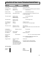
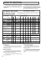
TROUBLESHOOTING - Machine does not start
CAUSE
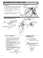
Control Settings
SOLUTION
STEP 1: Ensure that the ON-Off toggle switch is in the "ON" position
and that the Pressure Control Knob is fully CW (maximum pressure).
Also check that the unit is plugged in.
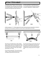
STEP 2: Lower the pressure control assembly and check if the
red power light on the board is lit. If the light is "OFF", proceed to
Step 3. If the light is "ON", go to Step 7.
Power Source
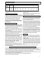
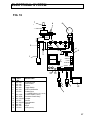
STEP 3: Use a multimeter to check for 110 volts VAC across the L1 and L2
terminals on the board. If no voltage at these leads, there is no power to the
unit. Check power source (outlet, breakers, extension cord and power cord).
Thermal Overload
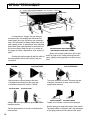
STEP 4: Disconnect the two red motor leads (S1 & S2) and test for continuity
between the two leads. Continuity shows that the motor's thermal coupler has
not tripped. No continuity means that thethermal coupler has opened due to excessive motor heat. If the motor is still hot to touch, allow to cool and retest. If
the motor is cool and there is no continuity on the red leads, contact your local
Leeson repair facility to repair/replace the thermal coupler.
Pressure Control
Assembly (Board)
STEP 5: If all checks out fine in Steps 1 through 4 and the red light is still
out, the pressure control assembly is defective and must be replaced.
Sensor
STEP 6: If the red light is "ON", the power source, fuse and thermal coupler
are okay. Plug another sensor into the board. If the unit starts, the sensor was
faulty and must be replaced. When a replacement sensor is not available, use
a multimeter to test the resistance between the BLACK and RED wires on the
sensor lead. The resistance should be approximately 1.5-3.5 kohms. A faulty
sensor usually reads zero resistance (open).
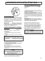
STEP 7: With the machine still "OFF", remove the potentiometer lead from
Pressure Control
Knob (Potentiometer) the board and read the resistance between the red and black wires. This must be
8 - 12 kohms. If outside this range, replace the potentiometer.
NOTE: A bad POT will usually show no resistance (open).
28
Motor
STEP 8: Remove the two black motor leads (A1 &A2) and test for continuity
between them. Continuity is an indication that the motor is sound. The lack of
continuity, points to a problem in the motor. If there is no continuity on these
two leads, check the motor brushes. Ensure thatthe brushes are evenly worn
and make solid contact with motor commutator. Replace the brushes if they are
less than 3/8" long. If the brushes are okay, replace the motor.
Pressure Calibration
STEP 9: Calibrate the pressure control assembly in accordance with the instructions on page 25-26.
Pressure Control
Assly. (Board)
STEP 10: If the unit fails to calibrate and all components in Steps 1-9 test
okay, the pressure control assembly needs to be replaced.