1
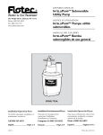
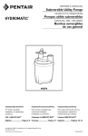
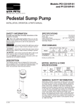
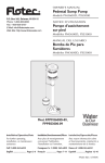
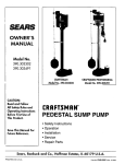
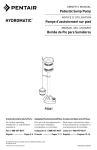
OWNER’S MANUAL
Smart GeyserTM
Submersible Utility Pump
293 Wright St., Delavan, WI 53115
Phone: 1-800-468-7867
1-800-546-7867
Fax:
1-800-390-5351
®
3671 0300 INT SIM
MODEL 2330-03
Installation/Operation/Parts
For further operating, installation,
or maintenance assistance:
Call 1-800-468-7867
English . . . . . . . . . . . . . . . Pages 2-4
©2005
SIM566 (Rev. 9/28/06)
Safety
2
GENERAL SAFETY
Electrically powered utility pumps normally give many
years of trouble-free service when correctly installed,
maintained, and used. However, unusual circumstances
(interruption of power to the pump, dirt/debris, flooding
that exceeds the pump’s capacity, electrical or mechanical failure in the pump, etc.) may prevent your pump
from functioning normally. To prevent possible water
damage due to flooding, consult your retailer about a
secondary AC pump, a DC backup pump, and/or a high
water alarm. See the “Troubleshooting Chart” in this
manual for information about common pump problems
and remedies. For more information, see your retailer or
call Simer customer service at 1-800-468-7867.
1. Know the pump application, limitations, and potential hazards.
Do not use in explosive atmospheres.
Pump water only with this pump. Failure to follow
this warning can result in personal injury and/or
property damage.
2. Make certain power source conforms to requirements
of your equipment.
Pump motor is equipped with an automatic resetting thermal protector and may restart
unexpectedly.
12.
Risk of electric shock. This equipment is
only for use on 115 volt (single phase) and is
equipped with an approved 3-conductor cord and 3prong, grounding-type plug.
To reduce risk of electric shock, be certain that it is connected to properly grounded,
grounding-type receptacle.
Where a 2-prong wall receptacle is encountered, it
must be replaced with properly grounded 3-prong
receptacle installed in accordance with the National
Electrical Code and local codes and ordinances.
13. All wiring should be performed by a qualified
electrician.
14. Protect electrical cord from sharp objects, hot surfaces, oil, and chemicals. Avoid kinking cord. Replace
or repair damaged or worn cords immediately.
3. Disconnect power before servicing.
15. Use wire of adequate size to minimize voltage drop
at motor. Refer to most recent National Electrical
Code.
4. Release all pressure within system before servicing
any component.
16. Do not touch an operating motor. Modern motors can
operate at high temperatures.
5. Drain all water from system before servicing.
SPECIFICATIONS
6. Secure discharge line before starting pump. An unsecured discharge line will whip, possibly causing personal injury and/or property damage.
Power supply required ................................115V, 60 HZ.
Motor duty .....................................................Continuous
7. Check hoses for weak or worn condition before each
use, making certain all connections are secure.
Liquid Temp. Range ..............................Max. 77°F (25°C)
8. Periodically inspect pump and system components.
Keep pump and system free of debris and foreign
objects. Perform routine maintenance as required.
Individual Branch Circuit Required ....................15 Amp
Operation Position ...............................................Vertical
Operating Depth
(water level)
Beginning min.........................3/4"
Ending max. ............................1/4"
9. Provide means of pressure relief on pumps whose discharge line can be shut-off or obstructed.
Discharge ...............................................1" NPT (25 mm)
10. Personal Safety:
DESCRIPTION
a. Wear safety glasses at all times when working
with pumps.
b. Keep work area clean, uncluttered and properly
lighted – replace all unused tools and equipment.
c. Keep visitors at a safe distance from the work
area.
d. Make workshop child-proof – with padlocks, master switches, and by removing starter keys.
11. When wiring an electrically driven pump, follow all
electrical and safety codes, as well as most recent
National Electrical Code (NEC) and Occupational
Safety and Health Act (OSHA).
The submersible pump is designed for water removal in
home applications. Pump can be used for emergency
service and dewatering. Unit is constructed of hi-impact
corrosion resistant plastic. Screened inlet prevents large
solids from entering pump.
NOTICE: This unit is not designed for applications involving salt water or brine! Use with salt water or brine will
void warranty.
PERFORMANCE
3'
(0.91)
5'
(1.52)
GPH (LPH) AT TOTAL FEET (M)
10'
15'
18'
20'
(3.05)
(4.57)
(5.49)
(6.09)
1600 gal 1524 gal 1260 gal 924 gal 648 gal 372 gal
(6 057 L) (5 769 L) (4 770 L) (3 498 L) (2 453 L) (1 408 L)
For parts or assistance, call Simer Customer Service at 1-800-468-7867
/ 1-800-546-7867
22'
(6.70)
0 gal
(0 L)
Installation / Operation
INSTALLATION
Do not use power cord to lift motor.
Always use handle.
1. Pump should be located and should rest on level
solid foundation. Do not suspend pump by means of
discharge pipe or power cord. Keep pump inlet
screen clear.
2. Thread outlet pipe into pump body carefully to avoid
stripping or crossing threads.
a. To install with garden hose, install adapter provided with pump.
NOTICE: To keep friction as low as possible,
hose must be 5/8" or larger. Keep hose as short as
possible.
b. To install with rigid pipe, use plastic pipe. Wrap
thread with Teflon tape or use Plasto Joint Stik*.
Screw pipe into pump hand tight +1 - 1-1/2
turns.
3. If, in your application, backflow is a problem when
the pump stops, prevent it by installing a 1" NPT
check valve in the pump discharge.
4. Power Supply: Pump is designed for 115V., 60 HZ.
operation and requires an individual branch circuit
of 15 amperes or more capacity. It is supplied with a
3-wire cord set with grounding-type plug for use in a
3-wire, grounded outlet. 3 wire extension cord, of at
least 14 AWG (2mm2) size is suggested, with larger
sizes for runs over 25 ft (7M). For safety, pump
should always be electrically grounded to a suitable
electrical ground such as a grounded water pipe or a
properly grounded metallic raceway, or ground wire
system. Do not cut off the round grounding prong.
The pump motor is equipped with
automatic resetting thermal protector and may
restart unexpectedly. Protector tripping is indication
of motor overloading as a result of operating pump
at low heads (low discharge restriction), excessively
high or low voltage, inadequate wiring, incorrect
motor connections, or a defective motor or pump.
OPERATION
Risk of burns or death from electric shock.
Do not handle pump or pump motor with wet hands or
when standing on wet or damp surface, or in water.
Disconnect power from pump before handling, servicing, or attempting to repair pump.
3
The Smart GeyserTM is fully automatic in operation. The
“smart” controller starts the pump every 2-1/2 minutes
and causes it to run for 5 seconds. If it senses that there
is no water to the pump, it stops. If it senses water, it
continues to run until the water is pumped down to 1/4"
deep, and then it stops. It then goes into a
7-minute quick-detection cycle, starting 4 times the first
minute, twice the second minute, and once a minute for
the next 5 minutes. If by the last check it has not detected water, it resumes its cycle (running 5 seconds every
2-1/2 minutes) until it senses water again.
NOTICE: When you plug the pump into the wall outlet,
it will start and run for 5 seconds. It will then cycle as
described above.
If the unit is put in the water and started, interrupting the
water flow into the pump during the 5-second watersensing run will cause it to wait 2-1/2 minutes before
restarting (instead of 15 seconds).
1. The motor is equipped with an automatically resetting thermal overload protector. If the motor gets too
hot, the overload protector will stop the motor
before it is damaged. When the motor has cooled
sufficiently, the overload protector will reset itself
and the motor will restart.
NOTICE: If the overload protector stops the pump
repeatedly, disconnect the power from the pump and
check it to find the problem. Low voltage, long extension cords, clogged impeller, too much back pressure
in the discharge hose (as when pumping through 50’
(15 M) of coiled hose), or extended running of pump
with no load, can all cause overheating.
2. The water being pumped cools the motor, allowing
the pump to run continuously at any depth of water
above 1/4". However, if the motor overload stops the
pump, allow it to cool for one hour before restarting.
Motor will not restart before the overload has cooled.
AIRLOCKS
When a pump airlocks, it runs but does not move any
water. An airlock will cause the pump to overheat and
fail. This pump has an anti-airlock hole in the bottom of
the pump body. If you suspect an airlock, unplug the
pump, clean out the anti-airlock hole with a paper clip
or piece of wire, and restart the pump.
NOTICE: If the outlet of the discharge hose/pipe is
submerged you must have a 1/8" hole in the discharge
hose/pipe to prevent airlock. This hole must be open to air.
NOTICE: If you move the pump or the pump airlocks, be
sure to drain the hose before trying to restart the pump.
* Lake Chemical Co., Chicago, Illinois
For parts or assistance, call Simer Customer Service at 1-800-468-7867
/ 1-800-546-7867
Repair Parts / Troubleshooting
4
REPAIR PARTS
5
Key
1
2
3
4
5
•
Part Description
Screen
Shield
Impeller
Motor
Power Cord
Garden Hose Adapter
Qty.
1
1
1
1
1
1
Part No.
PS8-6P
PS70-3P
PS5-25P
**
PS117-51-TSU
FT0013-43
NOTICE: To purchase a check valve, call Customer Service at
1-800-468-7867 and order part number PW73-63.
** If motor fails, replace entire pump.
• Not Illustrated.
4
Anti-Airlock
Hole
Orient Part Number with
Anti-Airlock Hole as shown
Anti-Airlock
Hole
Tighten 1st
3
2
1
3rd
5125 0905
2nd
Assemble Screen and Shield as shown.
TROUBLESHOOTING
Risk of electrical shock and sudden start.
Disconnect electrical power to pump before attempting to troubleshoot or work on it.
SYMPTOM
Pump won’t
start or run
POSSIBLE CAUSE(S)
Blown fuse
Low line voltage
Defective motor
Impeller
Pump operates
but delivers little
or no water
Low line voltage
Something caught in impeller
Small diameter garden hose
or long discharge line
Check valve installed without
vent hole
Air lock
Coils or bends in hose
CORRECTIVE ACTION
If blown, replace with fuse of proper size
If voltage under recommended minimum, check size of wiring
from main switch on property. If OK, contact power company.
Replace pump
Remove screen, locate source of binding
Use only 14 gauge or larger extension cords. Use short extension cords
when necessary
Clean out impeller
Use larger diameter garden hose or 1" flexible pipe. Eliminate any
excess hose. Short hoses work best
Drill a 1/16" - 1/8" (1.6 - 3.2 mm) dia. hole between pump
discharge & check valve
Turn off pump for a few seconds, clean out anti-airlock hole and restart pump
Straighten hose
For parts or assistance, call Simer Customer Service at 1-800-468-7867
/ 1-800-546-7867