1
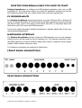
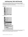
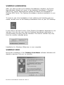
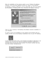
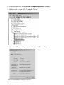
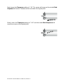
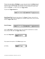
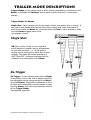
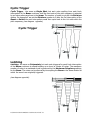
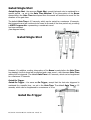
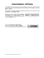
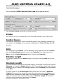
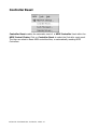
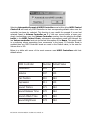
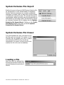
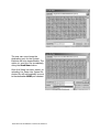
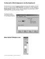
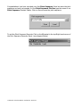
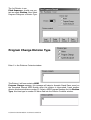
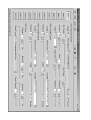
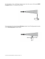
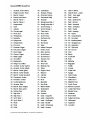
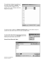
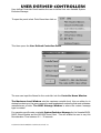
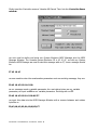
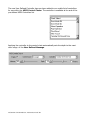
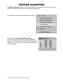
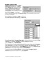
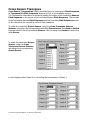
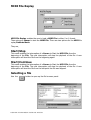
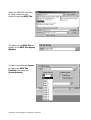
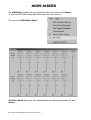
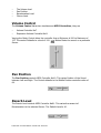
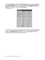
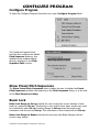
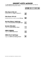
desktop SOUNDBEAM
users manual
Version 1
February 2004
Page
Page
Page
Page
Page
Page
Page
Page
Page
Page
2. Contents
4. Desktop Soundbeam what you need to start
6. Installing The Software
7. Installing The Interface
17. A Lighting Tour of the Controls
21. Range
25. Divisions
27. Divisions Offset
30. Transpose
32. Trigger Modes
Trigger Modes Descriptions
Single Shot, Re-Trigger,
Poly Sustain, Clyclic Trigger,
Latching, Gated Single Shot,
Gated Re-Trigger
Page 39. Polyphony
Page 40. MIDI Control Chains
Control Source
Gate
Relative Length
Absolute Length
Air Fader
Speed
Page 43. MIDI Controllers
Page 44. MIDI Set-up
Bank Hi Lo
Output Device
Output Channel
Page 47. Menu
File Load Patch
Open as Read Only
Save
Load Channel
Save Channel
Import Set-up
Export Set-up
Page 51. MIDI
MIDI Port Settings
Selecting a MIDI Input
Controller Reset
System Exclusive File Import
System Exclusive File Viewer
Organise Set-ups
Page 58. Organise Set-ups
Page 60. Tools Menu
To Record a Pitch Sequence
Record events from the Sensor via the Sensor Event Recorder
Define a User Defined Controller
Access the Channel Level Monitor
Select the Patch Macro Settings Panel
Select the MIDI Mixer
Page
Page
Page
Page
Page
Page
Page
Page
65.
66.
67.
68.
74.
75.
77.
81.
Load a user Pitch Sequence
Randomise Pitch Sequence
Pitch Sequence Divisions Types
Program Change Division Type
System Exclusive Division Type
Sensor Events Recorder
User Defined Controllers
Sensor Monitor
Page 82. Set-up Macro Settings
Global Transpose
Cross Sensor Global Transpose
Cross Sensor Transpose
MIDI File Replay
Page 88. MIDI Mixer
Volume Control
Channel Mute
Pan Position
Reverb Level
Chorus Level
Master Level
Page 92. Configure Program
Pitch Sequence List
Beam Lock
Page 93. Short Cut Menu
File Open
File Save
Patch Macro Settings
MIDI Mixer
MIDI Port Settings
Desktop Soundbeam What you need to start
Desktop Soundbeam is a software and USB hardware application that runs on IBM
compatible PC. You must ensure before you install the application software and connect
the hardware interface that your system meets some minimum requirements.
PC requirements
For Desktop Soundbeam optimal performance you need: Windows ME or Windows XP
Home or Professional edition. A 6oomhz Pentium or Athalon processor, minimum of 64 mb
ram with at least 11mb of free space on Ultra DMA, Ultra ATA, or Ultra/Ultra Wide SCSI
hard drives, with 512k cache and USB connection.
If you are to install a third party Software Synthesiser or Sampler please refer to their own
recommended specifications.
Hardware Interface
The Desktop Soundbeam interface requires an USB connection to your host computer
without this you will be unable to use the interface unit. The interface comprises 3 separate MIDI interfaces, 8 channel variable voltage switch inputs, 4 ultrasonic sensor inputs/
outputs, USB connector and power input.
The interface connections are explained in detail below.
Front Panel Connections
Rear Panel Connections
Desktop Soundbeam Manual Page 4
Installing The Software
Insert the Desktop Soundbeam installation CD into your CD Drive. The installation
program should start automatically. Follow the on screen information installation
procedure as each operating system is slightly different. If the installation application does
not automatically start follow the instructions below.
Left click with your mouse on start icon, this is located on the bottom left hand corner of
your desktop,
Now click on run
Now type D:setup_dtsb.exe into the dialogue, box if your cd drive is another drive letter
other than D then type drive letter of your cd drive followed by :Setup_dtsb.exe
Now click on OK, the installation application should now run.
Desktop Soundbeam Manual Page 6
Installing the interface
Installing the Interface
Connect the USB cable to the rear panel of the Desktop Soundbeam interface. Now
connect the opposite end of the USB cable to your host PC USB Socket. Next connect
the power supply unit to your mains socket output, now connect the cable to your
Soundbeam desktop power input located on the front right hand side of the interface.
Now Connect your Sensor drivers via the supplied cable to the corresponding sensor
inputs located on rear of the Desktop Soundbeam interface unit, connect the other
free end of the cable to your sensor driver corresponding socket.
Next, connect your sensor to the corresponding sensor socket on your sensor driver.
Connect any switches you wish to use to the switch inputs on the front panel of the
interface.
Finally, connect your Sound Module or Sampler to your Desktop Soundbeam interface.
To MIDI Output 1 to the corresponding MIDI input on your Sound Module or Sampler.
Now turn on your desktop Soundbeam.
Your computer operating system will now automatically detect the Desktop Soundbeam
Interface has been connected. Each operating system behaves in a slightly different
way.
The Desktop Soundbeam application is at the moment only supported on Windows Xp,
Windows Millennium AND Windows 2000. However, an upgrade will shortly be
available for Windows 98. This will be available as a download from the Soundbeam
website.
As installation for each operating System is slightly different, please refer to each operating system in turn.
Desktop Soundbeam Manual Page 7
Windows Millennium
After you have turned on the desktop Soundbeam’s interface, the Found
New Hardware Wizard will report it has detected Soundbeam 2 Desktop
USB Driver, shortly afterwards the wizard will detect the Soundbeam 2
Desktop MIDI Driver. The Desktop Soundbeam interface installation is complete.
To check to see if the installation of the software and interface was successful, double click on the Desktop Soundbeam Icon on your PC’s desktop.
In the bottom left hand corner of the Desktop Soundbeam application is an
indicator, this tells the user that the Desktop Soundbeam application is
communicating correctly with the interface. The Version number may vary
from the number indicated below.
Installation for Windows Millennium is now complete.
Windows 2000
During the installation of the Desktop Soundbeam software Windows will
display a warning Click yes to continue.
Desktop Soundbeam Manual Page 8
After the installation of the sotware switch on your Desktop Soundbeam
interface, the Found New Hardware Wizard will report it has detected
Soundbeam 2 Desktop USB Driver, shortly afterwards the wizard will detect
the Soundbeam 2 Desktop MIDI Driver. Windows will display a warning
Click on yes to continue. The Desktop Soundbeam interface installation is
now complete.
To check to see if the installation of the software and interface was successful, double click on the Desktop Soundbeam Icon on your PC’s desktop.
In the bottom left hand corner of the Desktop Soundbeam application is an
indicator, this tells the user that the Desktop Soundbeam application is
communicating correctly with the interface. The Version number may vary
from the number indicated below.
Desktop Soundbeam Manual Page 9
Windows XP
REPLACING THE DEFAULT WINDOWS XP DRIVERS
The Windows XP operating system contains drivers that work with the
Desktop Soundbeam. However, the Soundbeam drivers provide greater
stability and to ensure compatibility with the Desktop Soundbeam application and interface.
You MUST follow these instructions to replace the Windows Xp Drivers.
Failure to do this will prevent the Desktop Soundbeam application and
interface from communicating and working correctly.
1. Open the Control Panel Window by clicking on Start/Control Panel.
Desktop Soundbeam Manual Page 10
2. Double click the “System” Control Panel.
3. Select the “Hardware” tab.
Desktop Soundbeam Manual Page 11
4. Click the “Device Manager” button.
5. Click on the ‘+’ next to ‘Universal Serial Bus Controllers’.
Desktop Soundbeam Manual Page 12
6. Check to see if the heading ‘USB Composite Device’ appears.
7. Double-click on the ‘USB Composite Device’.
8. Select the “Driver” tab, and click the “Update Driver...” button.
Desktop Soundbeam Manual Page 13
9. When the Hardware Update Wizard appears, select “Install from a
specific location (Advanced)” and click “Next”.
10. Select the option “Don’t search, I will choose the driver to install”, click
“Next”.
Desktop Soundbeam Manual Page 14
11. On the next screen select the Soundbeam 2DT USB Driver and click
“Next”.
12. A warning that the driver has not passed Windows logo testing will
display. Ignore this and click “Continue Anyway”.
Desktop Soundbeam Manual Page 15
13. Windows will copy files and then two things will occur in quick succession:
a) The Update Device Driver Wizard will display a dialog box indicating it
has finished installing the software for this device and requesting you to
click the “Finish” button.
b) The Found New Hardware Wizard will report it has detected an Unknown
Device.
14. Click the “Finish” button on the Upgrade Device Driver Wizard screen.
15. Repeat steps 9 to 12, selecting the Soundbeam MIDI Driver this time.
If you are asked what type of hardware you are trying to install, select
’Sound Video and Game Controller’.
16. Click the “Finish” button to finish the installation.
17. To check to see if the installation was successful, double click on the
Desktop Soundbeam Icon on your PC’s desktop.
18. In the bottom left hand corner of the Desktop Soundbeam
application is an indicator, this tells the user that the Desktop
Soundbeam application is communicating correctly with the
interface.
Desktop Soundbeam Manual Page 16
A LIGHTNING TOUR
of the controls
Main application interface
A LIGHTNING TOUR of the controls
The main screen of the application contains the most often used functions in one visible
area, in the following exercise we will create a Set-up. A Set-up is a complete collection
of settings for the 4 ultrasonic sensor inputs as well as the 8 inputs from the switch
interface. As we are already in a default Set-up. Start by making changes to Beam 1. As
no other sensor has been selected this sensor should currently be active. The first sensor
is always selected each time the program is started. We will start by selecting a Pitch
Sequence for Beam 1
A Pitch Sequence, is any sequence - scales, arpeggios, tunes - of up to 64 single notes
or 2-, 3- or up to 10 note chords. They can be assigned to up to 64 Divisions of the
Sensor. Soundbeam can store a library of Pitch Sequences. 17 of these are Locked
Pitch Sequences which cannot be altered by the user. You can define the other Pitch
Sequences by using a MIDI keyboard to play the notes or chords into one of the Dekstop’s
3 MIDI IN inputs.
We will now alter the pitch
sequence for Sensor 1, move your
mouse over the Pitch Sequence
selector click the down arrow icon,
this will open up a listing of all the
available pitch sequences.
Lets change the default Pitch
Sequence Chromatic scale to a
Major Triad 7 9 11, this is done by
selecting the pitch sequence by
either using the up and down arrow
keys, or by clicking on the pitch
sequence with a left mouse click.
if you have connected a Sound
Module or Sampler to MIDI output
port 1, try moving your hand in front
of the sensor, you should hear a scale
moving up and down in pitch
depending on the position relative to
the sensor. Try selecting other pitch
sequences, and then re - select
Major Triad 7 9 11.
Try selecting the Reverse function, by clicking with the left mouse button over the
selector box , this will reverse the order of the Pitch Sequence.
Desktop Soundbeam Manual Page 19
And finally try selecting Enable, this will either transmit the notes or other MIDI data that
is contained within the pitch sequence to the selected MIDI Output port.
Desktop Soundbeam Manual Page 20
Range
The Maximum Range of Soundbeam is the furthest distance from the within which
interruptions of the Beam will be detected. It can be set to any distance from 0.56m to
6.00m. The Default Range is 0.60m and, unless you change the Default Range setting,
0.60m will be selected each time you Load up a Set-up.
Note that interruptions of the first 20 cm of the Beam from the Sensor will not result in any
notes being triggered.
At this point, there are two possibilities you might like to try.
First, If you have plenty of clear space - 5m x 5m, say - you could try extending the length
of the beam to 3m. This is done by positioning your mouse cursor over the Maximum
Range Slider and clicking your left mouse button, dragging the Slider to the right increases the active length of the beam, drag the Slider until the Maximum Range setting
is 3m.
If you wish to increment the Range in steps of 1 cm to fine tune the length of the beam,
try using the Left and Right arrow buttons next to the maximum range window.
Desktop Soundbeam Manual Page 21
And the Sensor will now send pulses to - and listen to echoes from - interruptions of the Beam up
to 3 m away.
Now, try walking towards the Sensor from, say, 4m away (in the direction which the
Sensor is pointing) - listening for the exact place where your body meets the furthest end
of the Beam from the Sensor and starts to generate sounds.
Next, walk in and out of the 3m long Beam, listening to what happens and trying to judge
when you’re interrupting the Beam and when you’re outside it.
Desktop Soundbeam Manual Page 22
Finally, Reduce the Maximum Range setting to 1.00m. This is a Range - a length of
Beam -
It is also possible to select a Minimum Range which defines the distance between the
Sensor and the nearest part of the Beam which will respond to interruptions.
This distance can be varied between 20cm and - depending on the Max Range setting up to 5.60m. It can never be greater than Max Range (6.00) minus 0.40m. The default
setting is 20cm.
Desktop Soundbeam Manual Page 23
The Active Area of the Beam - within which interruptions will be detected and used to
send MIDI messages articulating musical notes - is the area between the Max and Min
Range settings
The Inactive Area of the Beam is that part between the Sensor and the Min Range
setting. While interruptions of this area will not normally trigger any notes of the selected
Pitch Sequence, they will silence - or ‘clear’ -notes or chords generated in Poly Sustain
or Retrigger Sustain. See trigger modes page??
Desktop Soundbeam Manual Page 24
Divisions
Divisions are the numbers of sections (from 1 to 64) into which the Beam or Switch can
be divided. Each division can contain from a single note up to a maximum of ten notes per
division.
We will now change the number of divisions for Beam 1 you can alter this by positioning
your mouse pointer over the Divisions Slider apply a left mouse click over the Slider icon
dragging the mouse either left to reduce the number of divisions or right to increase the
number of divisions.
The default Set-up within the Soundbeam Desktop application sets each sensor to 16
divisions.
Try selecting 1 division, try movements along the beam, you should hear that the number
of notes along the beam has reduced to 1.
Desktop Soundbeam Manual Page 25
Now try say 3 divisions you should only trigger 3 notes along the length of the beam.
Now put the divisions setting back to 16.
TIP
If you wish to increment the number of divisions in smaller steps try using
the Left and Right arrow buttons next to the divisions number window, this
enables you to increment the number of divisions in division steps.
Desktop Soundbeam Manual Page 26
Divisions Offset
Divisions Offset – defines the note (or chord) of the selected Pitch Sequence from
which to start the Pitch Sequence in relation to the Sensor.
For Example if we use the Preset Chromatic Scale Pitch Sequence this contains 64
separate divisions containing single notes (see diagram on opposite page).
With a Divisions number of 16 selected Beam 1 will play notes from Division number 32
(G2) to Divisions number 47 (Bb3). (See Diagram Below)
Desktop Soundbeam Manual Page 27
If we now adjust the Divisions Offset Slider to 1
we will now play from Division 1 (C0) thru to Division 16 (Eb1). (see diagram below)
If the Divisions Offset number is changed to 8 and the divisions number reduced from
16 to 3 then the sensor would trigger divisions number 8 (G0) to 10 (A0). (see diagram
below)
Desktop Soundbeam Manual Page 29
Transpose
This enables the whole Pitch Sequence - the sequence of notes which is heard when you move
your hand backwards and forwards to and from the Sensor - to be shifted up (+) or down (-) by
the number of semitones you set with the Slider control.
To try this out, move your hand backwards and forwards in the Beam
(towards and away from the Sensor). Transpose for Beam.
Move the Transpose Slider to change the Transpose setting - first to +19. You will
hear the notes of the Pitch Sequence shifted an octave and a fifth above the original
pitch.
Desktop Soundbeam Manual Page 30
Next change the Transpose setting to “-26”. The screen will show and the whole Pitch
Sequence will sound 2 octaves and a tone below the original pitch.
Finally, return the Transpose setting to “+00”. and the whole Pitch Sequence will
sound once more at the original pitch.
Desktop Soundbeam Manual Page 31
Trigger Modes
The Trigger Modes are the different ways of starting and stopping the notes sounded by
interruptions of the Beam. You will find a full description of the effects of the various
articulations listed on page 21.
For the moment, listen to the effect - on the sounds produced by movements of your hand in the Beam - of one or
two different Trigger Modes.
As we are in the Default Set-up the trigger mode should be set to Re-Trigger
Re-Trigger
Desktop Soundbeam Manual Page 32
Now select Polysustain trigger mode
In Poly Sustain Mode - if you are using sounds which can be sustained indefinitely
(e.g. organ, choir, bowed strings, wind instruments) - each time you make a fresh interruption of the Beam, a new note will be sounded and sustained, even when the interruption ceases.
Each new interruption adds a note to a growing chord or cluster of notes, which will
continue to sound until you silence it by passing your hand through the Inactive Area
of the Beam, close to the Sensor.
Note, however, that - unlike Re-Trigger - if, after interrupting the Beam, you move
your hand towards or away from the Sensor, no new notes will be sounded until you
remove your hand from the Beam, and then re-enter it again.
Try moving your hand in the Beam at various distances from the Sensor.
Polysustain
Next, select “Retrig Sustain”
Desktop Soundbeam Manual Page 33
This has the same effect as Retrigger - as you move your hand in the Beam towards
and away from the Sensor, again you articulate a series of notes, but this time all the
notes you trigger go on sounding until you pass your hand through the inactive area
close to the Sensor - or switch to the next Trigger Mode.
Try the other Trigger Modes like
Gated Single Shot Separate interruptions of the Beam will trigger notes which are
sustained (if no other notes are triggered) for a variable length of time, set by the user
with the Trigger Time setting.
Gated Retrigger
Same as Re-Trigger , except that the last note triggered is sustained for a variable
time, set by the user with the Trigger Time setting.
Now select Single Shot
Only separate interruptions of the Beam trigger notes.
and finally,
Desktop Soundbeam Manual Page 34
Trigger Mode Descriptions
Trigger Modes are the various ways in which sounds generated by movements in the
Beams, or activated by Switches, can be made to start, stop and, in some cases,
overlap;
Trigger Modes for Beams
Single Shot - plays a single note for the length of each interruption (but no longer). A
new note is only played when the first interruption ceases and a new interruption is
made from outside the Beam. No movement within the Beam, either towards or away
from the Sensor triggers other notes.
(see diagram below).
Single Shot
NB. Some of the sounds on your keyboard,
sound module or sampler may be programmed
for the notes to decay - i.e.. to die away to
nothing over a short period, rather than to stop
abruptly. The decay will not be affected by a
MIDI “Note-Off” command resulting from the
cessation of an interruption of the Beam.
Re-Trigger
Re-Trigger - a note is played every time the Beam
is interrupted, and a new note is played whenever
the interruption moves (along and within the Beam)
to a new Division. This produces a glissando or flurry
of notes as the interruption moves towards or away
from the Sensor -this is the most frequently used of
all the Trigger Modes;
(see diagram opposite).
Desktop Soundbeam Manual Page 35
Poly Sustain
Poly Sustain - the same as Single Shot, but each note resulting from each fresh interruption of the Beam continues to sound building up a chord or cluster of notes. The
maximum number of notes in a sustained chord is governed by the Maximum Polyphony settings for the Beam. The notes can be silenced by interrupting the Beam
in the Inactive Area between the Sensor -and the Min Range setting.
(see diagram below).
Poly Sustain
Re-Trigger Sustain
Retrigger Sustain - the same as Retrigger, but - in this case - each note resulting from
an interruption of the Beam moving towards or away from the Sensor continues to
sound, building up a chord or cluster. As before the sounds can be silenced by
interrupting the Inactive Area of the Beam.
(see diagram below).
Re-Trigger Sustain
Desktop Soundbeam Manual Page 36
Cyclic Trigger
Cyclic Trigger - the same as Single Shot, but each note resulting from each fresh
interruption of the Beam continues until the next note of the pitch sequence is selected
by an interruption anywhere in the beam. The number of notes is set with the Divisions
setting. For example if we set the Divisions number to 3 after the 3rd interruption of the
Beam or Switch the next interruption would then cycle back to the 1st note within the
pitch sequence, (see diagram opposite).
Cyclic Trigger
Latching
Latching - the same as Polysustain, but each note triggered by each fresh interruption
of the Beam continues to sound building up a chord or cluster of notes. The maximum
number of notes in a sustained chord is governed by the Maximum Polyphony settings
for the Beam. The notes can be silenced by interrupting the Beam in the same division at
which the sound was originally triggered.
(see diagram opposite).
Desktop Soundbeam Manual Page 37
Gated Single Shot
Gated Single Shot - the same as Single Shot, except that each note is sustained for a
specific period - as set in the Gate Time Window. If the interruption of the Beam
ceases before the Gate Time has elapsed then the sound will continue to sound for the
duration of the gate time.
The default Gate Time is 0.5 seconds, which can be varied to a maximum 10 seconds,
the triggered sound will continue to be heard to the end of the time period set, providing
a MIDI Program No. representing a sustained sound
has been selected.
(see diagram below).
Gated Single Shot
However, if in addition, another interruption of the Beam is made before the Gate Time
has elapsed, the first sound will be silenced and a new sound – with the same Gate Time
setting will be triggered. The default Gate Time is 0.5 seconds, which can be lenghtened
to a maximum 10 seconds.
Gated Re-Trigger
Gated Re-Trigger - the same as Re-Trigger, except that the last note triggered is
sustained for a specific time - as set in the Gate Time. The default Gate Time is 0.5
seconds, which can be lengthened to a maximum of 10 seconds. (see diagram below).
Gated Re-Trigger
Desktop Soundbeam Manual Page 38
Polyphony Setting
In Soundbeam and other electronic instruments, polyphony means the number of musical
notes which can be played simultaneously. The maximum is 32 simultaneous notes per
Beam or Switch.
This function is particularly valuable for regulating the density of the sound when using
Polysustain and Retrigger Modes.
Starting once again from the Preset scale Pentatonic Scale, Use the Slider Control to select
the maximum number of simultaneous notes you
require for Beam 1, to 10.
Now Select Polysustain Trigger Mode.
After 10th successive interruption of Beam 1
the 1st note sustained will automatically be turned off.
Desktop Soundbeam Manual Page 39
MIDI Control Chains A B
Soundbeam Desktop enables the simultaneous control of two real time MIDI
Controller Messages.
This is selected via MIDI Controller Chain A and B. (see diagram below)
Each Control Chain A and B has the same functions.
Enable
This turns off or on the transmission of the Controller selected in the control chain.
Control Source
Five different categories of control information based on the information derived from
interruptions of the Beam can be assigned as Sources for Control Chains A and B.
They are
Gate
Any interruption of the Beam - and its withdrawal. If an object moves into the Beam,
then the Control Depth setting is sent to the Controller. If an object leaves the
Beam, then the Control Minimum setting is sent to the Controller.
Relative Length
The (changing) distance from the Sensor relative to the point at which the Beam was first interrupted.
Absolute Length
An output between the Minimum and Depth setting, for example if you set the controller
Minimum to 0 and the Depth setting to 100. The controller output level will vary
between 0 and 127 relative to the changing distance from the Sensor of an interruption
of the Beam.
A positive value for the Control Depth setting means that the value of Absolute
Length will increase to its maximum as the interruption gets nearer the Sensor, and
decrease to its minimum as it gets nearer the extreme limit set by Range. A negative
value, on the other hand, means that the value of Absolute Length will drop to its
minimum as the interruption approaches the Sensor.
Desktop Soundbeam Manual Page 40
Air Fader
The changing position of an interruption of the Beam relative to the Sensor - acts as a
virtual fader on the MIDI Controller it is being sent to. For example, if the Destination
setting is MIDI Controller No 7 - Channel Volume - with a Control Minimum setting
of 0, and a Control Depth setting of 100 - an interruption of the Beam at the furthest
point from the Sensor would transmit a Channel Volume of 0 - i.e.. silence. Moving the
interruption along the Beam towards the Sensor would offer a steady increase in the
volume of the sound - to its maximum at the point nearest the Sensor. If at any point in
its movement the interruption ceases, the volume of the sound will remain constant at
that level, until another interruption passes through the point in the Beam at which the
previous interruption had ceased, when the volume of sound will again start changing up
or down in accordance with the direction of the interruption’s movement towards or away
from the Sensor.
Speed
A number between the Minimum and Depth setting relative to the speed of the movement of an interruption within the Beam.
Minimum
Sets the Minimum level transmitted from the selected MIDI Controller, for example if
we set the Control Source to Speed and the Minimum to 064 and the depth to 100
the slowest possible movements within the Beam would send a Minimum controller value
64, the fastest possible movements would send a level of 127.
Depth
Depth selects the maximum level of control to be allowed to the MIDI Controller. For
the selected MIDI Controller.
Reverse
This reverses the depth control setting, for example if you wanted to reverse say the
speed on movement within a Beam so that slow movements create louder musical output
set MIDI Control Chain A to the following (see diagram below)
Desktop Soundbeam Manual Page 41
We have set Control Chain A to the Following:
Enable: Enabled
Control: Source Speed
Controller: Note Velocity
Minimum:127
Depth:100
Reverse: Enabled
Because Controller Minimum is set to 127 the slowest possible movements produces a
high Note Velocity level. The Depth control will now set how much reduction to the
Controller Minimum level the faster movements within the Beam, reduces the
Minimum Level setting.
Desktop Soundbeam Manual Page 42
MIDI Controllers
Controller selects the destination for settings from Control Source, Minimum and Depth
settings.
Controller Contentions
If the user selects the same MIDI Controller for Either Control Chain A or B then only
one control chain can only send one MIDI Controller of the same type.
In the screen shot below you can see that each Control Chain A and B both have Bank
Select message as the MIDI Control Chain Destination. As you can see the visible
appearance of the MIDI Controller selected in MIDI Control Chain B is different from
that in Control Chain A. This is even though they are of the same type of MIDI
Controller. This is because the user is unable to select the same type of MIDI
Controller in Each MIDI Control Chain. If the user subsequently tries to re select the
same controller type that is in Control Chain A that they are prevented from selecting
the MIDI Controller of the same type.
For example sending Pitch Bend in Control Chain A from Speed, and Pitch Bend in
Control Chain B from Relative Length, this would result in a rather confusing MIDI
Controller Message.
Desktop Soundbeam Manual Page 43
MIDI Setup
MIDI Setup This is used to access settings for a number of different possibilities - for
assigning MIDI Program and MIDI Port settings.
You may like to try just one of these MIDI Settings for Program Number, since you can
use it to explore the various sounds stored in your MIDI musical instrument.
We will now make changes to the Program Slider Control
MIDI Program Nos. denote the various sounds - or timbres - available in your
MIDI musical instrument. scroll through the changing sounds from “1” to “128” and
back to “91” - using your other hand in the Beam to hear them.
Desktop Soundbeam Manual Page 44
Bank Hi Bank Lo
Bank Hi Bank Lo enables in combination with MIDI Program Number for the user to
select alternative Banks of sounds. These messages are commonly called Bank Select
Messages. Their are two MIDI controllers that are commonly used for this purpose they
are MIDI Controller 0 MSB and MIDI Controller 32 LSB.
Changes are made with the Bank Controller Slider the On selector enables the Bank
Controller value to be sent . As with any Bank Select Message this is used in combination with the MIDI Program Change.
For example if we wanted to select a MIDI Program Number of say 1 with a Bank
Select Message LSB (Bank Lo) of 42, we would select Program 1 with the Program
Slider, then selecting a value of 41 using the Bank Lo Slider Control, finally selecting
On to send the MIDI Controller Message. (see Diagram Below)
Desktop Soundbeam Manual Page 45
Output Device
Output device enables the sum of all the current settings for either the 4 Beams and 8
Switches to the sent to a corresponding MIDI Output.
Try selecting USB Audio Device [2] will send the settings for the Pitch sequence
Generator, MIDI Controller Chains A and B plus settings for MIDI Setup to the 1st
MIDI Output on the Desktop Soundbeam Interface.
Below is a listing of the available MIDI Input/Output Ports and their coresponding
names.
Desktop Soundbeam MIDI out1
Desktop Soundbeam MIDI out2
Desktop Soundbeam MIDI out2
Desktop Soundbeam MIDI In1
Desktop Soundbeam MIDI I n2
Desktop Soundbeam MIDI In3
Output Channel
Output Channel selects the coresponding MIDI Output Channel form 1 to 16. Use the
MIDI Output Channel Slider Control to Select one of the available 16 MIDI
Channels.
MIDI Output Channel
Desktop Soundbeam Manual Page 46
Menus
Their are several other Menus within the Desktop Soundbeam application, they are
described below.
FILE
Load Set-Up
Load Patch loads a Set-up file already created, select the file you wish to load then click
on the open button to load the file.
Open as Read only
This enables a file to be loaded into the application but the user is unable to save any
subsequent changes, unless the user chooses to Save As and then re-name the Set-up
file before saving.
Desktop Soundbeam Manual Page 47
Save
Enables a user to save any changes to a current file, there are a number of Preset
Set-up files these are locked “Read Only” files. If you wish to save any changes to
preset files use the Save As function described below
Save Set-Up As
Enables the user to name a Set-up File before saving the file.
Load Channel As
Load Channel enables the user to Load the settings for a sensor already saved. This
option is useful if you already have a setting for a particular Sensor already saved and
you would like to Load its settings into your current Set-up.
Desktop Soundbeam Manual Page 48
Save Channel As
Save Channel enables the user to save the settings for the currently Selected Sensor.
This option is useful if you already have a setting for a particular Sensor in one Set-up
and you would like to save this setting so it can be Loaded using Load Channel into
another Set-up at a later date.
Import Set-Up
This enables the user to Import a Set-up file including any custom made Pitch Sequences
that may be included witihin the Set-up.
Desktop Soundbeam Manual Page 49
Export Set-Up
As Set-up files and Pitch Sequence files are saved as separate files .
The Export Set-up function enables the user to save any custom made Pitch Sequences
that may be included with the Set-up and the Set-up as one complete file. Exporting a
Set-up automatically includes any custom made Pitch Sequences that may be included
within the Set-up. On Importing the Set-up the Pitch Sequences are automatically
saved into the Pitch Sequence directory.
Exit
Closes the application.
Desktop Soundbeam Manual Page 50
MIDI
MIDI Port Settings
Enables the user to select the MIDI input Port to enable the following functions:
•
To Route MIDI Data for recording to the Pitch Sequence Recorder:
•
Set-up List Arranger application:
To Select a MIDI Port Click on the
MIDI Port Settings Icon. There is also a short cut Icon
for this setting on the top area of the main application screen.
MIDI Port Settings Icon
Selecting MIDI Input Port
To select a MIDI Input Port click on the MIDI Port Settings Icon, this will open the
MIDI Port Settings Panel, then select the MIDI Input Port you wish to use. For
example Desktop Soundbeam MIDI In1 connects the Desktop Soundbeam Interface MIDI Input 1.
Desktop Soundbeam Manual Page 51
Selecting MIDI Input Channel
Click on the MIDI Receive Channel Drop down list to select one of the 16 available MIDI
Channels. Click on OK to save the Setting.
Allow Program Change Set-up Selector
This enables a MIDI program change message recived via the currently selected MIDI
input to load a Set-up contained in the Set-up Selector panel. The Index number in the
Set-ups list corisponds to the MIDI program number. See page 57 for further details.
Interface MIDI Loopback
The Interface MIDI Loopback setting enables the MIDI output port of the Soundbeam
MIDI interface to loop the MIDI messages from any of the 3 MIDI outputs to be looped
back to the corresponding MIDI inputs.
Desktop Soundbeam Manual Page 52
This is useful when you wish to control a third party MIDI software directly from the
Soundbeam MIDI output port. For example if we wanted to control Reason software
studio from Desktop Soundbeam we would need to do the following:
1.
2.
3.
4.
Select Desktop Soundbeam MIDI Out1 for the sensor MIDI output port.
Enable MIDI 1 Loopback
Select Desktop Soundbeam MIDI Input1 as your MIDI input in Reason.
Click on Ok to finish
Select Desktop Soundbeam MIDI Input 1 as a MIDI Input in Reason. You may loop all
3 MIDI output ports in the same way. Once the MIDI Loopback function has been enabled the corresponding MIDI input and Output sockets on the interface will no longer
transmit or receive any MIDI signals until the Loopback function is disabled. Once the
Soundbeam Application is closed the corresponding MIDI inputs and outputs are reset
to normal operation.
Desktop Soundbeam Manual Page 53
Controller Reset
Controller Reset enables the automatic reset of a MIDI Controller Used within the
MIDI Control Chains. Click on Controller Reset to select the Controller reset panel.
The User can select to Reset MIDI controllers Now, or automatically resetting MIDI
Controllers.
Desktop Soundbeam Manual Page 54
Selecting Automatically reset all MIDI Controllers used within either MIDI Control
Chains A B will reset any MIDI Controller to their coresponding default value once the
controller has been de- selected. This function is very useful for example if a user had
selected Speed to Volume Controller no 7. if the user moved within a beam very
slowly, transmitting a very low Volume Controller number, then de selecting the Controller in the MIDI Control Chain, subsequent interruptions would still transmit the
low Volume controller level set via the last interruption of the Beam. This would result
in a confusing silence emanating from movements in the beam. If Controller Reset is
enabled then any MIDI Controller levels are reset to the Default value, in the case for
Volume this is 100.
Below is a table with some of the most common used MIDI Controllers with their
default values.
MIDI Controller
Num ber Default Value
Modulation
001
00
Volum e
007
100
Pan Position
010
064
Expression
011
100
So und T i m b r e
071
064
Sound Release T im e
072
064
Sound A ttack T im e
073
064
Sound Brightness
074
064
Desktop Soundbeam Manual Page 55
System Exclusive File Import
Enables the user to Import a MIDI System Exclusive file
for transmission to their Sound Module or Keyboard.
System Exclusive messages can contain complicated
messages to enable a user to setup their Sound module
or Keyboard in expressive ways. For example changes to
reverberation, delay and chorus can be programmed via
their Module or third party editor, this can then be saved
as a System Exclusive file for loading into the System
Exclusive file Import Panel. Clicking on the SysEx
File Import heading will open up the file System
Exclusive File Import Panel.
System Exclusive File Viewer
This panel enables the user to browse for the
file they wish to transmit. The option in the
Transmit Port list enables the user to select
the destination MIDI Port for the file for
transmission. An option to Send the file now
enables the file to be sent immediately.
Loading a File
Once the user has selected the
file from the browser window, the
panel will display the contents of
the file.
Desktop Soundbeam Manual Page 56
The user can now choose the
destination port for the System
Exclusive file to be transmitted to. The
option to send the file immediately,
using the Send Now button.
Once the Setup has been saved, on
reloading the Setup the System Exclusive file will automatically be sent
to the destination MIDI port selected.
Desktop Soundbeam Manual Page 57
Organise Set-ups
The Organise Set-ups panel enables the user to do the following. To arrange in order
from the number of available set-ups into a order for selecting via either MIDI Program
Change messages via the MIDI input Port Selector. Or using switch inputs one and
two to cycle upwards or downwards though the selected Set-ups.
On the Left hand side of the panel is a list of the currently available
Set-ups. Each Set-up can be highlighted, and dragged across from the Available
Setups listing into the Setup List.
The Index Number next to the Set-up name is the corresponding MIDI Program
Number that will select the corresponding Set-up from the list via the MIDI Input
selected.
Using Switch inputs one and two the user can cycle upwards and downwards through
the available Set-ups in the Set-up List. If you wish to delete any of the available
Set-ups in the Setup List click on the Set-up and use the delete button on your
keyboard to remove the Set-up. More than one copy of any Setup can be included in the
List.
Desktop Soundbeam Manual Page 58
The remote select MIDI Input Program Change checkbox enables or disables MIDI
Program Change messages to load the Set-up. Switches 1&2 checkbox enables or
disables switch selection of the Set-up.
Desktop Soundbeam Manual Page 59
Tools Menu
The tools Menu enables the user to access the
following functions.
•
To Record a Pitch Sequence
•
Record events from the Sensor via the
Sensor Event Recorder.
•
Define a user defined controller
•
View the Sensor Monitor
•
Select the Set-Up Macro Settings Panel
•
Select the MIDI Mixer
Pitch Sequence Recorder
This enables the user to Load, Save, Record and modify a Pitch Sequence.
A pitch Sequence can contain three types of MIDI data They are:
•
•
•
Single or multiple MIDI notes up to 10 notes per division
MIDI Program Data
System Exclusive Messages
Highlight the Pitch Sequence Record listing to
open the Pitch Sequence Recorder Panel.
Desktop Soundbeam Manual Page 60
To Record a Pitch Sequence
First ensure you have selected the correct MIDI Input port to record MIDI data from, and
have connected your MIDI Output from your MIDI Keyboard. Next select the type of
division you wish to record notes. Enable recording by pressing the Record button. The
Pitch sequence recorder will now record MIDI note data from the MIDI input. To stop the
recording press the Stop button. To save the Pitch Sequence type in a name in the Pitch
Sequence File Box. Now press Save to save the Pitch Sequence.
If you wish to Play the sequence to listen and make any changes to the Sequence you
have just recorded, select a MIDI Port for the Sequence to be played, then use the Play
button to play the division. To select another division use division list selector.
(see diagram below)
Pitch Sequence Division Selector
Desktop Soundbeam Manual Page 61
To Record a Pitch Sequence via the Keyboard
Another option is to use your computer keyboard to record a pitch sequence, this way
you do not need to connect a MIDI Keyboard. The first step is to insert number of
divisions your pitch requires 21 notes. You can insert a division by pressing the Insert
Division Button. The pitch Sequence Recorder defaults to one note division, so we
need to press the insert division button 21 times.
The Divisions number
should have increased to
22. (see Diagram Opposite)
Now Select Division one
Desktop Soundbeam Manual Page 62
Now Select the type of Division we
require, as we are recording note
information then select Note as
the division type. Now type in via
your Computer keyboard the following four notes separated by a space
between each note D3 A2 G2 D2
into the Divisions contents window.
The Divisions contents window can
contain up to ten note chords.
Now continue to the next division, select Notes as the division type and type A3 in the
Divisions contents window. Continue on recording to the 22nd division from the diagram.
22 - Note Pitch Sequence “ Scottish Fiddler”
Desktop Soundbeam Manual Page 63
Congratulations! you have recorded your first Pitch Sequence. Now lets save the pitch
sequence we have just created. In trhe Pitch Sequence File Box type the name of our
Pitch Sequence Scottish Fiddler. Click on Save to save the pitch sequence.
To exit the Pitch Sequence Recorder. Click on the X located in the top Right hand corner of
the Pitch Sequence Recorder Panel. (see diagram Below)
Desktop Soundbeam Manual Page 64
To Load a User Pitch Sequence
Open the Pitch Sequence Recorder Panel, select the Load Pitch Sequence Icon ,this
Icon
locates the Folder Containing your own custom made Pitch Sequences.
Load Pitch Sequence Icon
The Open Pitch Sequences Panel displays
your current custom made Pitch
Sequences click on the file you wish to
load followed by the Open button. This
will load the selected Pitch Sequence into
the Pitch Sequence Recorder for
further editing or modification.
Desktop Soundbeam Manual Page 65
Randomise Pitch Sequence
The Randomise Pitch Sequence function enables you to randomise two types of event
for the selected Pitch Sequence.
• The Pitch Sequence Order
• Sequence
Randomise Order
This Randomises the Order of Divisions within the Pitch Sequence.
Randomise Notes
This Randomises the Notes within the Pitch Sequence.
Invert Pitch Sequence
Invert Pitch Sequence
reverses the order of the
Divisions in the Pitch
Sequence
Desktop Soundbeam Manual Page 66
Pitch Sequence Division Types
There are 3 types of MIDI Data that can be placed into a Pitch Sequence Division,
they are
•
•
•
Notes
Program Change
System Exclusive
We will add a series of MIDI Program numbers into our already created Pitch Sequence
Scottish Fiddler.
Open the Pitch Sequence Recorder panel and load the Scottish Fiddler Pitch
Sequence.
As the Pitch Sequence Recorder is already
on division one lets insert an empty division, we do this by pressing the Insert
Division
button.
Desktop Soundbeam Manual Page 67
The 1st Division in our
Pitch Sequence should now contain an empty Division. Now Select
Program Change as a Division Type.
Program Change Division Type
Enter 1 in the Divisions Contents window.
This Division 1 will now contain a MIDI
Program Change message, this message will select a Acoustic Grand Piano sound on
the connected General MIDI Module when this division is interrupted. Insert another
division this time at division number 23. Select a MIDI Program Message for this Division
Type, this time type in number 90 Warm Pad into the Division Contents window.
Desktop Soundbeam Manual Page 68
Now Select Save,
you will be prompted with a warning,
Select Yes to over write the existing pitch sequence. You have now created a pitch Sequence Containing 24 divisions with Division 1 and 24 containing MIDI Program Messages.
Exit the Pitch Sequence Recorder Panel.
Assign this Pitch Sequence to Beam 1, Select Divisions number to 24, this the number
of Divisions within our Pitch Sequence. Select Divisions Offset of 1, this will play our
Pitch Sequence from the 1st Division. Now select Retrigger Mode as our Trigger Type.
Lastly ensure that your Sound Module is connect to Desktop Soundbeam MIDI Out1.
Desktop Soundbeam Manual Page 69
On interruption of the 1st Division furthest away from the sensor will transmit MIDI
Program number of 1 Acoustic Grand Piano.
Movements along the beam between Divisions number 2 and 23 will generate the notes
of our Pitch Sequence Scottish Fiddler.
Desktop Soundbeam Manual Page 71
On interrupting the 24th Division closest to the sensor will transmit the MIDI program number of 90 Warm Pad.
Desktop Soundbeam Manual Page 72
Desktop Soundbeam Manual Page 73
System Exclusive Division Type
System Exclusive MIDI Messages are custom MIDI messages that correspond to a
particular Musical Instrument Manufacturer. We can insert into a Pitch Sequence Division System Exclusive messages. As each type of System Exclusive message is
unique to a particular manufacturer.
All System Exclusive messages contain a series of status bytes, they all start with the
universal message F0 this tells the connected instrument that a system exclusive message
has started.
This is normally followed by a series of bytes that are unique to the instrument. The
Manufacturers identification followed by the parameters you wish to control.
For Example Yamaha’s message would start as F0 43 10 4C XX XX XX XX XX XX F7.
the bytes 43 10 4C are Yamaha’s identification bytes, XX are the bytes you would wish to
control. F7 tells the instrument that you have ended the System Exclusive message. The
message below will change the master volume level of most Yamaha XG modules, including the MU15, 50, 128 Sw1000 sound card.
F0 43 10 4C 00 00 04 7F F7
the eighth status byte message 7F message turns up the master volume level to
maximum.
we can input this data into a pitch
sequence by selecting System
Exclusive as our Division type.
The Maximum number of status bytes permitted per division is 51.
Desktop Soundbeam Manual Page 74
Sensor Events Recorder
The Sensor Events Recorder enables you to record the output from each separate
sensor. This can be saved as a comma separated file format for importing into a 3rd
party software package like Exel for further analysis. To open the recorder select.
This will open the Sensor Events Recorder Panel.
Desktop Soundbeam Manual Page 75
The vertical axis displays the position of
the object interrupting the Sensor. The
horizontal position displays the time
duration, this is also indicated within the
Elapsed time display.
The Record button enables the Sensor Event Recorder, the Stop button stops the
recorder the clear button clears the currently recorded events.
To save the file select Save this will open the file save
panel enter the name into the File Name panel, then
selecting the save button saves the file.
Sensor Events Recorder Panel.
Desktop Soundbeam
Manual Page 76
User Defined Controllers
User defined Controller Panel enables the user to define their own Variable System
Exclusive Message.
To open the panel select Tools Menu then click on.
This then opens the User Defined Controllers Panel.
The user can input the Name for the controller into the Controller Name Window.
The Maximum Level Window sets the maximum variable level, this can either be in
decimal numbering or the more commonly used hexadecimal numbering that most sythesiser
manufacturers provide. The MIDI Message Window is where the custom message
type is created.
For example we will create a variable System Exclusive Message for the Yamaha MU50,
MU15 Sound Module and the SW1000 Sound Card. This will enable the user to vary the
Reverberation Time between 0.1 - 30 seconds.
Desktop Soundbeam Manual Page 77
Firstly input the Controller name as ‘Yamaha XG Reverb Time’ into the Controller Name
window.
we now need to define and enter our System Exclusive MIDI Message into the MIDI
Message Window. The Yamaha System Exclusive ID is 43 10 4C, as with any System
Exclusive MIDI Message we need to start this message with an F7, so our message should
be.
F7 43 10 4C
we now need to enter the reverberation parameters onto our existing message, they are.
F0 43 10 4C 02 01 42 00
as our message needs a variable parameter, the next status bytes are our variable
parameter, we input an XX as our variable parameter. Finishing with an F7.
F0 43 10 4C 02 01 42 00 XX F7
we input this data into the MIDI Message Window with a comma between each status
byte like so
F0,43,10,4C,02,01,42,00,XX,F7
Desktop Soundbeam Manual Page 78
The next step is to define our variable parameter Minimum and Maximum parameters
as this data is given normally in Hexadecimal numbering we will input this data in this
format.
The minimum variable parameter is 00 the Maximum value is 45. We input the data like
so.
Next click on the
button, if you have placed the data into the
Controller Name, Maximum Value, Minimum Value and MIDI Message
Windows correctly then the question mark button will change to a
button, click on this button to save the controller.
Click on the close icon to close the User Defined Controller Panel.
Desktop Soundbeam Manual Page 79
The new User Defined Controller has now been added to our usable list of controllers
for use within the MIDI Control Chains. The controller is available at the end of the
pre defined MIDI Controllers list.
Applying the controller to the control chain automatically sets the depth to the maximum range of the User Defined Message.
Desktop Soundbeam Manual Page 80
SENSOR Monitor
The Sensor Monitor displays information about the interruption and position of any of
the four ultrasonic sensor inputs or the eight switch inputs.
To open the panel select Tools Menu then click on.
This will open the Sensor Monitor Panel.
The Four left-hand channels correspond to Beam
inputs 1 to 4. Followed by the next 8 inputs to Switch
inputs 1 to 8. The monitor can be positioned anywhere
on your desktop.
Desktop Soundbeam Manual Page 81
Set-Up Macro Settings
Patch Macro Settings Panel enables the user to set the following sensor controls.
•
•
•
•
Global Transpose all sensors
Global Transpose from any source sensor
Transpose from one sensor to another
MIDI File Replay triggered from any
sensor
Desktop Soundbeam Manual Page 82
Global Transpose
Global Transpose transposes all Pitch
Sequences assinged to the 4 Beams
and 8 Switch inputs within the current
Set-up. Global Transposition is superimposed on top of any individual
Transposition settings already assinged
to any of the Sensors. To alter the
Global Transpose setting using the Controller Slider. The transposition range is plus
or minus 72 semitones.
Cross Sensor Global Transpose
Cross Sensor Global Transposition enables the interruption of one sensor’s Pitch
Sequence - to Globally Transpose the Pitch Sequences assigned
to all 4 Beams and 8 Switch Inputs.
The Transposition information is derived by adding the octave of the controlling Sensors
Pitch Sequence to the octave of the controlled Sensors Pitch Sequences. The
intervals of the Transposing Sensors Pitch Sequence Transposes all the Sensors Pitch
Sequences by the interval of the controlling Pitch Sequence.
To select the controlling Source Sensor, using the Cross Transpose Source
Selector, this assigns the corresponding Source Sensor.
Desktop Soundbeam Manual Page 83
Cross Sensor Transpose
Cross Sensor Transposition enables the interruption of one sensor’s Pitch Sequence
to Transpose the Pitch Sequence assigned to one of the available sensor’s.
The Transposition information is derived by adding the octave of the controlling Sensors
Pitch Sequence to the octave of the controlled Sensors Pitch Sequence. The intervals
of the Transposing Sensors Pitch Sequence shifts the controlling Pitch Sequence amount
by the interval of the controlling sensor’s Pitch Sequence.
To select the controlling Source Sensor, using the Cross Transpose Sources
Selector, this assigns the corresponding controlling Source Sensor. Any Beam or Switch
input can control one of the available Sensors. You can assign any Sensor to control any
other Sensor.
To select the controlling Source
Sensor, using the Cross
Transpose Sources Selector,
this assigns the corresponding
Source Sensor.
In the Diagram below Switch 8 is controlling the transposition of Beam 1.
Desktop Soundbeam Manual Page 84
MIDI File Replay
MIDI File Replay enables the user to load a MIDI File in either 0 or 1 format.
Then using any Sensor to start the MIDI File. There are two options for the MIDI file
replay Reatime Mode.
They are,
Start/Stop
This mode enables the interruption of a Sensor to Start the MIDI File from the
beginning of the File. The next interruption will stop the playback of the file. A new
interruption will start the file from the beginning again.
Start/Continue
This mode enables the interruption of a Sensor to Start the MIDI File from the
beginning of the File. The next interruption will stop the playback of the file. A new
interruption will start the file from the last point the file was stopped.
Selecting a file
Use the
button to open up the file browser panel.
Desktop Soundbeam Manual Page 85
Select the MIDI FIle you wish
to replay, select thr open
button to load the MIDI File.
The Name of the MIDI File will
appear in the MIDI File Replay
Window.
You can now select the Sensor
to trigger the MIDI File
Playback with using the
Source Selector.
Desktop Soundbeam Manual Page 86
The MIDI Output Port
Selector connects the MIDI file
playback to any available MIDI port
installed on your computer.
Desktop Soundbeam Manual Page 87
MIDI MIXER
The MIDI Mixer enables the user adjust the audio mix between any Sensor.
To open the MIDI Mixer Panel Select the tools menu then click on,
This opens the MIDI Mixer Panel.
The Mixer Panel allows you vary independently the following parameters for each
Sensor.
Desktop Soundbeam Manual Page 88
•
•
•
•
The Volume level
Pan Position
Reverberation Level
Chorus Level
Volume Control
The Volume Control Varies two simultaneous MIDI Controllers, they are
•
•
Volume Controller No7
Expression Volume Controller No11
Varying the Fader Control alters the controller from a Minimum of 000 to Maximum of
127. The control Defaults to a level of 100.
Button Mutes the sound on a particular
Sensor.
Pan Position
The Pan Position controls MIDI Controller No10. This varies Position of the Sound
between Left and Right. The Control defaults to the Middle Position controller value of
64.
Reverb Level
The Reverb Level controls MIDI Controller No91. This varies the amount of
Reverberation to the selected Sensor. The Default Level is 40.
Desktop Soundbeam Manual Page 89
Chorus Level
This varies MIDI Controller No93 the default level is 000.
Master Fader
The Master Fader controls the output level of the Sum of all Beams and Switches.
The relative levels between each sensor is maintained. A global Mute control using the
button.
MIDI Mixer
Each Sensor control automatically defaults to the MIDI Channel selected for each
particular Sensor. If more than one sensor is allocated to a particular MIDI Channel,
then the First Sensor allocated in Sensor order controls all subsequent Sensors
allocated to the same MIDI Channel.
Desktop Soundbeam Manual Page 90
For example if Beam 1 is allocated to MIDI Channel 1, we then allocate to Beam 2
the same MIDI Channel. The Controls for Volume, Pan Position, Reverb and
Chorus levels for Beam 1 will now override the controls for Beam 2. This stops the
duplication of controls for a particular MIDI Channel.
See diagram below.
You will see from the above diagram that the colour of Beam 2 Faders have changed, If
you now vary the Volume Fader for Beam 1 this will vary both sensors. If Beam 2 is
allocated to a MIDI Channel no longer in use by any other Sensor then the
appearance of the fader will revert to its default view.
Desktop Soundbeam Manual Page 91
configure Program
Configure Program
To Open the Configure Program Panel click to to open Configure Program Panel.
The Configure Program Panel.
Lets the user configure the default
Pitch Sequence directory, this
defaults to the installed default
directory displayed in the Pitch
Sequence Path window.
Show Preset Pitch Sequences
The Show Preset Pitch Sequences option enables the user to display the Preset
Pitch Sequences at either the beginning of the Pitch Sequence listing, or at the end
of the Pitch Sequence Listing.
Beam Lock
Beam Lock Range to Set-up enables the user to save the current settings of each
beam to a particular Set-up. This function is very useful where beam ranges may need
to be altered for each Set-up. Enabling Range to Set-up saves the beam range
information with the current Set-up. This information is then loaded with the Set-up.
Beam Lock Range to Beams overrides the currently save Beam Ranges with the
current range setting.
Desktop Soundbeam Manual Page 92
Short cuts Menus
The Icon Short-cuts enable the user to select the most commonly used features
without utilising the drop down Menus.
File Open Ctrl+O
Enables the user to Open a Set-up file.
File Save Ctrl+S
Enables the user to save the current Set-up.
Set-Up Macro Settings
Opens the Set-Up Macro Settings Panel.
Sensor Monitor
Opens the Sensor Monitor Panel.
MIDI MIXER
Opens the MIDI Mixer Panel.
MIDI Port Settings
Opens the MIDI Port Settings Panel.
Desktop Soundbeam Manual Page 93
The Desktop Soundbeam
The Desktop Soundbeam was deigned for
Edward and Judy Williams
by
Adam Fullerton: Interface
Firmware
Gerald McKenzie :Soundbeam Application
Mark Newbold :Specification, Installer, Software Testing, Manual,
Set-up design
Tim Orr: Hardware Design
Technical Support
Mark Newbold
The Soundbeam Project
Unit 3 Highbury Villas
Kingsdown
Bristol
BS2 8BY
Tel 0117 923 7075
Fax 0117 9706 241
Email [email protected]
Desktop Soundbeam Manual Page 94