1
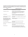
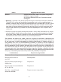
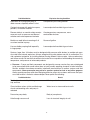
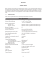
Varian Vacuum Technologies
121 Hartwell Avenue
Lexington, MA 02421-3133
(781) 861-7200
(800) 8-VARIAN
VHS-6
Diffusion Pump
Instruction Manual
Manual No. 6999-01-022
Revision E
July 2000
Sales and Service Offices
America
Varian Vacuum Technologies
121 Hartwell Avenue
Lexington, MA 02421,
USA
Tel: (781) 861 7200
Fax: (781) 860 5437
Toll Free: 1 (800) 882 7426
France
Varian s.a.
7 avenue des Tropiques
Z.A. de Courtaboeuf – B.P. 12
Les Ulis cedex (Orsay) 91941
France
Tel: (33) 1 69 86 38 38
Fax: (33) 1 69 28 23 08
Argentina
Varian Argentina Ltd.
Sucursal Argentina
Av. Ricardo Balbin 2316
1428 Buenos Aires
Argentina
Tel: (54) 1 783 5306
Fax: (54) 1 786 5172
Germany
Varian GmbH
Alsfelder Strasse 6
Postfach 11 14 35
64229 Darmstadt
Germany
Tel: (49) 6151 703 353
Fax: (49) 6151 703 302
Australia
Varian Australia Pty., Ltd.
6/81 Frenchs Forest Road
Frenchs Forest, NSW 2086
Australia
Tel: (61) 2 9975 8805
Fax: (61) 2 9452 2600
Hong Kong
Varian Technologies Asia, Ltd.
Rm 2611 Concordia Plaza
New Mandarin Plaza
1 Science Museum Rd.,
Tsimshatsui East, Kowloon
Hong Kong
Tel: (852) 26206173
Fax: (852) 26206338
Brazil
Varian Industria e Comercio Ltda.
Avenida Dr. Cardoso de Mello 1644
Vila Olimpia
Sao Paulo 04548 005
Brazil
Tel: (55) 11 820 0444
Fax: (55) 11 820 9350
Canada
Varian Canada
6705 Millcreek Drive, Unit 5
Mississauga, Ontario L5N 5R9
Canada
Tel: (800) 882 7426
Fax: (781) 860 5437
China
Varian China Ltd.
Room 1201, Jinyu Mansion
No. 129A Xuanwumen Xidajie
Xicheng District
Beijing 100031
P.R. China
Tel: (86) 10 6641 1530
Fax: (86) 10 6641 1534
Varian Shanghai
Service Station
716 Yishan Road Shanghai
P.R. China 200233
Tel: (86) 21 6483 5576
Fax: (86) 21 6485 9031
England
Varian Ltd.
28 Manor Road
Walton-On-Thames
Surrey KT 12 2QF
England
Tel: (44) 1932 89 8000
Fax: (44) 1932 22 8769
India
Varian India PVT LTD
1010 Compotent House
7, Nangal Raya Business Centre
New Delhi 110 046
India
Tel: (91) 11 5548444
Fax: (91) 11 5548445
Italy
Varian Vacuum Technologies
via Flli Varian 54
10040 Leini, (Torino)
Italy
Tel: (39) 011 997 9111
Fax: (39) 011 997 9350
Japan
Varian Vacuum Technologies
Sumitomo Shibaura
Building, 8th Floor
4-16-36 Shibaura
Minato-ku, Tokyo 108
Japan
Tel: (81) 3 5232 1253
Fax: (81) 3 5232 1263
Korea
Varian Technologies Korea, Ltd
Shinsa 2nd Bldg. 2F
966-5 Daechi Dong
Kangnam Gu, Seoul
Korea 135-280
Tel: (82) 2 3452 2452
Fax: (82) 2 3452 2451
Netherlands
Varian Vacuum Technologies
Rijksstraatweg 269 H,
3956 CP Leersum
The Netherlands
Tel: (31) 343 469910
Fax: (31) 343 469961
Mexico
Varian S.A.
Concepcion Beistegui No 109
Col Del Valle
C.P. 03100
Mexico, D.F.
Tel: (52) 5 523 9465
Fax: (52) 5 523 9472
Singapore
Varian Asia, Ltd.
1123 Serangoon Road
#03-02
Singapore 328207
Tel: (65) 296 9688
Fax: (65) 296 9733
Spain
Varian Iberica
Avda Pedro Diez 25
28019 Madrid
Spain
Tel: (34) 91 4727612
Fax: (34) 91 4725001
Russia
Varian Moscow
19A Khlebny per
121019 Moscow
Russia
Tel: (70) 95 9374280
Fax: (70) 95 9374281
Taiwan
Varian Technologies Asia Ltd.,
Taiwan Branch
18F-13 No.79, Hsin Tai Wu Road
Sec. 1, Hsi Chih
Taipei Hsien
Taiwan
Tel: (886) 2 2698 9555
Fax: (886) 2 2698 9678
Internet Users:
Visit us on the web at:
www.eVarian.com
Representatives in most countries
WARRANTY
Products manufactured by Seller are warranted against defects in materials and workmanship for
twelve (12) months from date of shipment thereof to Customer, and Seller's liability under valid warranty claims is limited, at the option of Seller, to repair, replacement, or refund of an equitable portion
of the purchase price of the Product. Items expendable in normal use are not covered by this warranty. All warranty replacement or repair of parts shall be limited to equipment malfunctions which, in
the sole opinion of Seller, are due or traceable to defects in original materials or workmanship. All
obligations of Seller under this warranty shall cease in the event of abuse, accident, alteration, misuse, or neglect of the equipment. In-warranty repaired or replacement parts are warranted only for
the remaining unexpired portion of the original warranty period applicable to the repaired or replaced
parts. After expiration of the applicable warranty period, Customer shall be charged at the then current prices for parts, labor, and transportation.
Reasonable care must be used to avoid hazards. Seller expressly disclaims responsibility for loss or
damage caused by use of its Products other than in accordance with proper operating procedures.
When products are used with toxic chemicals, or in an atmosphere that is dangerous to the health of
humans, or is environmentally unsafe, it will be the responsibility of the Customer to have the product
cleaned by an independent agency skilled and approved in handling and cleaning contaminated
materials before the product will be accepted by Varian Associates for repair and/or replacement.
Except as stated herein, Seller makes no warranty, express or implied (either in fact or by operation
of law), statutory or otherwise; and, except as stated herein, Seller shall have no liability under any
warranty, express or implied (either in fact or by operation of law), statutory or otherwise. Statements
made by any person, including representatives of Seller, which are inconsistent or in conflict with the
terms of this warranty shall not be binding upon Seller unless reduced to writing and approved by an
officer of Seller.
Warranty Replacement and Adjustment
All claims under warranty must be made promptly after occurrence of circumstances giving rise
thereto, and must be received within the applicable warranty period by Seller or its authorized representative. Such claims should include the Product serial number, the date of shipment, and a full
description of the circumstances giving rise to the claim. Before any Products are returned for repair
and/or adjustment, written authorization from Seller or its authorized representative for the return and
instructions as to how and where these Products should be returned must be obtained. Any Product
returned to Seller for examination shall be prepaid via the means of transportation indicated as
acceptable by Seller. Seller reserves the right to reject any warranty claim not promptly reported and
any warranty claim on any item that has been altered or has been returned by non-acceptable means
of transportation. When any Product is returned for examination and inspection, or for any other reason, Customer shall be responsible for all damage resulting from improper packing or handling, and
for loss in transit, notwithstanding any defect or non-conformity in the Product, in all cases, Seller has
the sole responsibility for determining the cause and nature of failure, and Seller's determination with
regard thereto shall be final.
If it is found that Seller's Product has been returned without cause and is still serviceable, Customer
will be notified and the Product returned at its expense; in addition, a charge for testing and examination may be made on Products so returned.
8/15/95
OPERATION AND MAINTENANCE OF THIS EQUIPMENT INVOLVES SERIOUS RISK. IT IS THE
RESPONSIBILITY OF THE USER TO MAINTAIN SAFE OPERATING CONDITIONS AT ALL TIMES.
VARIAN ASSUMES NO LIABILITY FOR PERSONAL INJURY OR DAMAGE RESULTING FROM
OPERATION OR SERVICE OF THE EQUIPMENT.
Carelessly or improperly operated equipment can cause serious injury or death and/or damage to the
equipment. The emergency and safety procedures in this manual are provided to help users and
qualified persons to operate and service the unit safely. Recommendations are believed to reflect
accepted industry practices in effect on the date of publication of this manual. Special applications
must be reviewed and approved by an industrial hygienist or chemical safety engineer.
Varian has no control over the use of this equipment and is not responsible for personal injury or
damage resulting from its use. The safe use and disposal of hazardous or potentially hazardous
materials of any kind is the sole responsibility of the user. Observe all WARNINGS and CAUTIONS
to minimize the serious hazards involved.
It is the sole responsibility of users of Varian equipment to comply with all local, state, and federal safety
requirements (laws and regulations) applicable to their system. Employ the services of an industrial
hygienist and/or a qualified chemical safety engineer in order to ensure safe installation and use.
This instruction manual contains information which will assist qualified operators in the operation, and
qualified service engineers to carry out field-servicing the Varian equipment.
i
SAFE INCORPORATION OF VARIAN DIFFUSION PUMPS INTO VACUUM SYSTEMS IS THE
RESPONSIBILITY OF THE SYSTEMS DESIGNER. TAKE APPROPRIATE ACTION THROUGH
REDUNDANCY, AND/OR OTHER SAFEGUARDS TO PROTECT PERSONNEL AND PROPERTY
FROM THE HAZARDS DESCRIBED BELOW AND IN THE INSTALLATION, OPERATION, AND
MAINTENANCE INSTRUCTION MANUAL. SAFE OPERATION IS THE RESPONSIBILITY OF THE
USING ORGANIZATION AND ITS PERSONNEL. READ THE INSTRUCTION MANUAL AND
UNDERSTAND HOW TO AVOID HAZARDS PRIOR TO OPERATING THE DIFFUSION PUMP. ALL
PERSONS WHO WORK WITH OR ARE EXPOSED TO DIFFUSION PUMPS OR EQUIPMENT
WHICH UTILIZES SUCH PUMPS OR DIFFUSION PUMP FLUID MUST TAKE PRECAUTIONS TO
PROTECT THEMSELVES AGAINST POSSIBLE SERIOUS BODILY INJURY OR DEATH. DO NOT
BE CARELESS AROUND SUCH PRODUCTS.
THESE SHEETS AND THE INSTALLATION, OPERATION, AND MAINTENANCE INSTRUCTIONS
CAN HELP YOU TO OPERATE THIS PUMP SAFELY AND EFFICIENTLY. READ THEM. SPECIAL
OPERATING CONSIDERATIONS AND PRECAUTIONS WILL BE FOUND IN THE OPERATION
INSTRUCTIONS. UNINFORMED OR CARELESS OPERATION OF THIS PUMP CAN RESULT IN
POOR PERFORMANCE, DAMAGE TO THE PUMP OR OTHER PROPERTY, SERIOUS BODILY
INJURY, AND POSSIBLE DEATH.
USERS OF THIS EQUIPMENT SHOULD BE ALERT TO TWO LEVELS OF HAZARDS IDENTIFIED
BY THE FOLLOWING SYMBOLS:
WARNING
_____________
Warnings are used when failure to observe instructions or precautions
could result in injury or death to humans.
CAUTION
________
Cautions are used when failure to observe instructions could result in
significant damage to equipment and/or facilities.
Designers of systems which utilize diffusion pumps must design out hazards wherever possible; provide guards, safety features, and interlocks for hazards which cannot be designed out; warn with
respect to hazards which cannot be designed out and which remain after utilizing guards, safety features, and interlocks; and lastly, provide procedures and instructions on proper use, servicing, etc., so
as to minimize risk.
ii
THE INSTALLATION, OPERATION, AND/OR SERVICING OR DIFFUSION PUMPS INVOLVES ONE
OR MORE OF THE FOLLOWING HAZARDS, ANY ONE OF WHICH, IN THE ABSENCE OF SAFE
OPERATING PRACTICES AND PRECAUTIONS, COULD POTENTIALLY RESULT IN DEATH OR
SERIOUS HARM TO PERSONNEL.
Hazard
Suggested Corrective Action
Loss of utility: water and/or electricity
Provide sufficient water and backup power to effect a safe
shutdown under worst case conditions.
Overpressure in foreline
Provide an interlock to ensure that the power supply to
the pump heater cannot be activated if the foreline pump
is not running AND/OR pressure in foreline is above
0.5 Torr (66.5 Pa).
Overtemperature
Fit temperature sensors and pump fluid level sensors with
feedback to an interlock on the heater power supply.
Insufficient water flow through the
main cooling coils
Use water flow sensor and feedback to interlock on the heater
power supply.
Water trapped between inlet and
outlet of quick-cool coil, or liquid
nitrogen trapped between inlet and
outlet of liquid nitrogen trap
Provide vent or pressure relief valves for both quick-cool coil
and liquid nitrogen trap.
Loss of ground integrity
Incorporate ground fault interrupt circuit into heater
power supply.
Positive pressure in pumping system
Integrate pressure relief valve in vacuum system.
High voltage
Prevent personnel contact with high voltages; design and
attach warnings.
Toxicity/Corrosivity
Toxic and/or corrosive gases must be vented to a safe
location, ensuring adequate dilution or scrubbing to safe
levels, taking all action required to meet air quality standards.
iii
Hazard
Explosion
Suggested Corrective Action
Integrate pressure relief valves in all systems using pumps
10 inches or larger in diameter.
Do not use or recommend the use of hydrocarbon-based
pumping oils.
a. Explosion – Operation of the diffusion pump without prior and continuous evacuation (below 0.5
Torr (66.5 Pa)) or coolant and introducing a strong oxidizer (such as air) or explosive vapors or
powders or materials which may react with pumping fluids into a hot (above 300°F or 150°C) pump
can cause an explosion. Such an explosion can violently expel valves and other hardware, slam
open doors that are not designed for appropriate pressure relief, or burst other components of the
vacuum system. Serious injury or death may result from expelled parts, doors, shrapnel, and/or
shock waves.
b. All diffusion pumps are typically cleaned with acetone or alcohol. When combined with air, oxygen,
and other oxidizers, alcohol and most other solvents are very flammable and explosive. Never permit any trace of these cleaners to remain in or on the pump. Always remove all traces of alcohol
and acetone and other cleaners with clean, dry, oil-free compressed air.
Three elements are required: fuel, oxidizer, and source of ignition. A combination of temperature and
pressure can be a source of ignition. Most diffusion pump fluids except mercury are fuels. Hydrocarbon
oils are more prone to oxidize and explode than synthetic silicone-based oil. Oxidizers can be air (a
strong oxidizer) from a leak or can be deliberately introduced in a process or can be inadvertently
admitted to the system by operator or process controller error. Oxygen and other strong oxidizers are
even more dangerous. Certain conditions of temperature and pressure can cause a combustible mixture to explode. The larger the diffusion pump, the greater the risk of explosion and the greater the risk
of damage and/or injury. Never operate diffusion pumps larger than 10 inches in diameter with hydrocarbon oils without a full safety analysis for the complete system and application. Never operate any diffusion pump in the following ways because they increase the probability of an explosion.
Prohibited Action
Explosion-Causing Condition
Run pump with no cooling water
Overtemperature
Run pump with low level of
pump fluid
Overtemperature
Run pump without proper backing or
holding pump
Overpressure
Run pump when not evacuated below
0.5 Torr (66.5 Pa)
Overpressure
Admit air to, or rough through,
a pump with hot boiler
Overpressure plus strong oxidizer
iv
Prohibited Action
Explosion-Causing Condition
Open drain or fill plug while pump is
under vacuum, especially when it is hot
Overpressure plus strong oxidizer
Contaminate pump with explosive vapors,
powders, or reactive materials
Lower explosive threshold of gas mixtures
Remove, defeat, or override safety countermeasures such as pressure and thermal
switches and valve sequencer interlocks
Overtemperature, overpressure, more
combustible mixtures
Machine or weld without removing all oil
or solvent residue in pump
Source of ignition
Use unsuitable pumping fluid especially
in large pumps
Lower explosive threshold of gas mixture
Systems larger than 10 inches must be designed with pressure relief devices to provide safe pressure relief from internal explosions. Always recognize that safety devices can fail or malfunction. Provide redundant protection by installing devices having different failure modes, failure mechanisms,
and failure causes. Be certain that exhaust duct materials are capable of withstanding the corrosivity,
temperature, and pressure of exhausted products.
c. Pressure – Pumps and their components are designed for vacuum service; they are not designed
to be pressurized which could cause them to burst possibly expelling shrapnel at lethal velocities.
Serious accidents have been caused by intentional pressurization of vacuum systems and their
components. Never pressurize any part of a vacuum system for test or any other purpose.
Always provide pressure relief when designing diffusion pumps into systems and ensure that pressure relief motion is limited to safe envelopes. Never permit the following:
Prohibited Action
Result
Block inlet and vent of liquid nitrogen
trap and lines
LN2 trap and/or lines burst
Close isolation valves at inlet and discharge
of main watercooling coils and pump is
reheated
Water turns to steam and bursts coils
Pressurize pump body
Body of pump bursts
Hole through vacuum wall
Loss of structural integrity of wall
v
d. Poisonous and/or Corrosive Compounds – When pumping poisonous, reactive, and/or corrosive
gas, vapors, or chemicals, even proper operation and regeneration will not always ensure that all
hazardous materials have been totally removed. If hazardous gas, vapors, chemicals, or combustible
mixtures are pumped, sufficient quantities may exist during operation or remain after regeneration to
cause severe injury or death. Overheating the pump oil, exposing it to air or reactive materials, or
overpressurizing it above the normal operating range (approximately 1mTorr (.133 Pa)) will decompose the oil and possibly make it toxic. This is especially true of backstreamed mechanical pump oils
which are more volatile (unstable). Overheating of accidentally introduced or backstreamed mechanical pump oils cannot be protected against by thermal switches which are set for diffusion pump oil.
d. Refer to specific instruction manuals for detailed instructions and precautions. Always vent the
pump and relief valve to a safe location thus ensuring adequate dilution to safe levels, and take all
other action required to meet quality air standards. Always handle pump fluids and hardware with
an awareness of the possible deadly hazards involved and the necessity for great care and attention to safety precautions.
d. Diffusion pumps are typically cleaned with acetone or alcohol. Acetone, alcohol, and most other
solvents are irritants, narcotics, and depressants, and/or carcinogenic. Their inhalation and ingestion may produce serious effects. Even absorption through the skin can result in moderate toxicity.
Always ensure that cleaning operations are performed in large, well-ventilated rooms. Use of selfcontained breathing apparatus may be necessary depending upon the solvent type and vapor
concentration in surrounding air.
e. High Voltage – Diffusion pumps operate at voltages high enough to kill through electrical shock.
Design equipment utilizing these pumps to prevent personnel contact with high voltages. Securely
attach prominent hazard warnings. Personnel should always break the primary circuit to the power
supply when direct access to the heater or wiring is required.
f. Hot Surfaces – Boiler temperatures reach 530°F (275°C) which can cause serious burns when
touched. Always ensure that surfaces have cooled near room temperature before touching them.
g. Hot Coolant and/or Steam – The water used to cool the pump can reach scalding temperatures.
Touching or rupture of the cooling surface can cause serious burns. Water left inside quick cool
coils from previous use will turn to steam when the pump is reheated. This steam must be allowed
to escape without contacting personnel. Whenever possible, design the water system with interlock valves so that power cannot be applied to the pump unless water is flowing in the main cooling coils (not quick-cooling coils).
h. Cold Surfaces – Liquid nitrogen traps cooled by liquid nitrogen are commonly used in diffusion
pumps. Metal surfaces at liquid nitrogen temperature can cause severe frostbite if contacted by
unprotected skin. These surfaces remain cold for some time (at least a half hour) after the liquid
nitrogen has evaporated.
vi
i. Cold Coolant – Liquid nitrogen, a cryogenic liquid, is used in traps. If it is splashed on body tissues
or eyes, it can cause severe frostbite or blindness. The extremely low temperature of liquified nitrogen can cause skin damage similar to high temperature burns. Contact with the cold gas evolving
from the liquid may produce the same effect. Delicate tissues, such as the eye tissues, are most
easily damaged by exposure to cold gas or liquid. To minimize the risk of hazardous contact of cold
gaseous nitrogen with any part of the body, wear personal safety equipment recommended for use
with cryogenic materials including face shield, full-sleeved lab coat, and clean, dry gloves which fit
loosely so they can be thrown off quickly if frozen by contact with the gas.
j. Asphyxiation – If a large amount of liquid nitrogen is spilled in a small, poorly ventilated room or
equipment, death from suffocation can result. All diffusion pumps are typically cleaned with acetone
or alcohol. Acetone, alcohol, and most other solvents are very volatile (unstable). During cleaning,
the volatility of these cleaners may permit their gases to displace air and its life-supporting oxygen
which could cause death or serious injury by asphyxiation. Always ensure that cleaning operations
are performed in large, well-ventilated areas.
j. While still hot, the diffusion pump may also contain decomposed and/or overheated pump oils
which can also be an asphyxiant.
k. Large, Heavy Weights – Diffusion pumps larger than 10 inches in diameter require powerassisted equipment and the use of trained moving/installation personnel in order to avoid
dropping, slipping, and/or overturning the pump thus severely injuring personnel. Check weight
of equipment before lifting and do not stand under equipment being moved.
vii
WARNING
_____________
High voltages can kill. Always break the primary circuit to the power
supply before starting to work on the heater and/or its wiring.
WARNING
_____________
Diffusion pumps are typically cleaned with acetone, alcohol, or other
solvents.
When heated, sprayed or exposed to high temperature equipment,
these solvents become flammable and explosive, causing serious injury
or death. Do not use near a high-temperature source. Ventilate working area with a blower and use in large, well-ventilated room. When
heated or sprayed, solvents also becomes 4 to 5 times heavier than air
and will flow down, settling in tanks, pits, and low areas, thus displacing
air which can kill by asphyxiation. Use in a large, well-ventilated room.
Use of a self-contained breathing apparatus may be necessary.
Acetone, alcohol, and other solvents are irritants, narcotics, depressants, and/or carcinogenics. Their inhalation and/or ingestion may produce serious effects. Prolonged or continued contact with the skin will
result in absorption through the skin and moderate toxicity. Always
ensure that cleaning operations are carried out in large, well-ventilated
rooms, and wear eyeshields, gloves, and protective clothing.
WARNING
_____________
Varian has no control over the types of gases passing through this
pump. These are entirely under the control of the process user and/or
the hardware systems integrator. Frequently, process gases are toxic,
flammable, corrosive, explosive, or otherwise reactive. Since these
gases can cause serious injury or death, it is very important to plumb
the exhaust of the pump to the facility’s hazardous gas exhaust system
which incorporates appropriate filters, scrubbers, etc., to insure that the
exhaust meets all air and water pollution control regulations.
WARNING
_____________
Certain gases can become corrosive and toxic when trapped in oil.
Always wear protective gloves when handling dirty pump oil, drain it into
a closable container, and do not breathe the fumes of the oil. Always
use fully self-contained breathing apparatus.
viii
WARNING
_____________
Hot oils can cause serious burns. Wear protective gloves and long
sleeved, loose fitting, heat resistant garments when draining pump oil.
WARNING
_____________
When lifting some Varian diffusion pumps, use power-assisted equipment and trained moving/installation personnel to avoid dropping, slipping, and/or overturning the pump and severely injuring personnel.
Check weight of equipment before lifting and do not stand under equipment being moved.
CAUTION
________
Alcohol, acetone, and other solvents degrade O-ring materials reducing
their ability to hold a vacuum. Do not use acetone or other solvents on
O-rings. If necessary to clean O-rings, wipe with lint-free, clean cloth,
wash in detergent and water, or use a small amount of pump oil.
NOTE
________
Always dispose of used or dirty oil properly and in compliance with all
local, state, and federal environmental laws and regulations.
ix
Table of Contents
Section
Page
Section I – Installation . . . . . . . . . . . . . . . . . . . . . . . . . . . . . . . . . . . . . . . . . . . . . . . . . . . . . . . .
1-1
1-1
1-2
1-2-1
1-2-2
1-2-3
1-2-4
1-2-5
1-2-6
Specifications . . . . . . . . . . . . . . . . . . . . . . . . . . . . . . . . . . . . . . . . . . . . . . . . . . . . . . . . . .
Installation . . . . . . . . . . . . . . . . . . . . . . . . . . . . . . . . . . . . . . . . . . . . . . . . . . . . . . . . . . . . .
Unpacking . . . . . . . . . . . . . . . . . . . . . . . . . . . . . . . . . . . . . . . . . . . . . . . . . . . . . . . . . . . . .
Pump Oil Installation . . . . . . . . . . . . . . . . . . . . . . . . . . . . . . . . . . . . . . . . . . . . . . . . . . . . .
Vacuum System Connections . . . . . . . . . . . . . . . . . . . . . . . . . . . . . . . . . . . . . . . . . . . . . .
Cooling Water Connections . . . . . . . . . . . . . . . . . . . . . . . . . . . . . . . . . . . . . . . . . . . . . . . .
Electrical Connections . . . . . . . . . . . . . . . . . . . . . . . . . . . . . . . . . . . . . . . . . . . . . . . . . . .
Thermal Switch . . . . . . . . . . . . . . . . . . . . . . . . . . . . . . . . . . . . . . . . . . . . . . . . . . . . . . . . .
1-1
1-2
1-2
1-2
1-2
1-3
1-3
1-4
Section II – Operation . . . . . . . . . . . . . . . . . . . . . . . . . . . . . . . . . . . . . . . . . . . . . . . . . . . . . . . .
2-1
2-1
2-2
Startup Procedure . . . . . . . . . . . . . . . . . . . . . . . . . . . . . . . . . . . . . . . . . . . . . . . . . . . . . . .
Shutdown Procedure . . . . . . . . . . . . . . . . . . . . . . . . . . . . . . . . . . . . . . . . . . . . . . . . . . . . .
2-1
2-2
Section III – Maintenance and Service . . . . . . . . . . . . . . . . . . . . . . . . . . . . . . . . . . . . . . . . . . .
3-1
3-1
3-2
3-3
3-4
3-5
3-6
3-7
General . . . . . . . . . . . . . . . . . . . . . . . . . . . . . . . . . . . . . . . . . . . . . . . . . . . . . . . . . . . . . . .
Periodic Inspection . . . . . . . . . . . . . . . . . . . . . . . . . . . . . . . . . . . . . . . . . . . . . . . . . . . . . .
Cleaning . . . . . . . . . . . . . . . . . . . . . . . . . . . . . . . . . . . . . . . . . . . . . . . . . . . . . . . . . . . . . .
Cold Cap Removal/Installation . . . . . . . . . . . . . . . . . . . . . . . . . . . . . . . . . . . . . . . . . . . . .
Jet Assembly Removal/Installation . . . . . . . . . . . . . . . . . . . . . . . . . . . . . . . . . . . . . . . . . .
Heater Replacement . . . . . . . . . . . . . . . . . . . . . . . . . . . . . . . . . . . . . . . . . . . . . . . . . . . . .
Adding Pump Fluid . . . . . . . . . . . . . . . . . . . . . . . . . . . . . . . . . . . . . . . . . . . . . . . . . . . . . .
3-1
3-1
3-1
3-2
3-3
3-4
3-4
Section IV – Troubleshooting . . . . . . . . . . . . . . . . . . . . . . . . . . . . . . . . . . . . . . . . . . . . . . . . . .
4-1
4-1
4-2
4-3
Leakage . . . . . . . . . . . . . . . . . . . . . . . . . . . . . . . . . . . . . . . . . . . . . . . . . . . . . . . . . . . . . .
Outgassing . . . . . . . . . . . . . . . . . . . . . . . . . . . . . . . . . . . . . . . . . . . . . . . . . . . . . . . . . . . .
Poor Pump or System Performance . . . . . . . . . . . . . . . . . . . . . . . . . . . . . . . . . . . . . . . . .
4-1
4-1
4-1
Section V – Replacement Parts . . . . . . . . . . . . . . . . . . . . . . . . . . . . . . . . . . . . . . . . . . . . . . . .
5-1
x
SECTION I
INSTALLATION
Before unpacking and installing the VHS-6 Diffusion Pump, the user should thoroughly familiarize
himself with this instruction manual and the diffusion pump specifications (see Table 1). He should
also examine all other technical material supplied in order to gain a better understanding of the operating principles, limitations, correct application, and the hazards involved with the use of this equipment.
1-1
SPECIFICATIONS
Table 1 lists the specifications for all standard type 0184 models of the pump.
Table 1. Pump Specifications
Power Rating
2200 watts
Optimum Operating Range
1 x 10⁻³ to < 5 x 10⁻⁹ (Torr)
.133 Pa to < .000000665 Pa
Maximum Pumping Speed
(liters/sec – air)
(liters/sec – helium)
2400 with std cold cap; 1600 with extended cold cap
3000 with std cold cap; 2000 with extended cold cap
Maximum Throughput
(Torr liters/sec at 0.01 Torr (13.3 Pa))
3.5
Maximum Forepressure
No Load: 0.65 Torr (86.45 Pa)
Full Load: 0.55 Torr (73.15 Pa)
Backstreaming Rate at Pump Inlet
<5 x 10⁻⁴ mg/cm2/minute (with std cold cap)
Power Required (approximately)
120, 240, 208, 50/60 Hz, single phase
Warmup Time
9 minutes
Cooldown Time (using quick cool coil)
10 minutes
Fluid Charge
500 cc
Cooling Water Requirements
(max. inlet temperature)
(max. outlet temperature at foreline)
(general flow rate)
60/80 degrees F
120 degrees F
0.25 gpm
Pressure drop across coils
15 psi
Backing Pump Size Recommended
17 cfm for maximum throughput
Jet Assembly
4-stage, self-aligning, stainless steel
Foreline Baffle
Stacked half moon
Cold Cap
Nickel-plated Copper
Water Connections
1⁄ 8
Thermal Switches
Manual reset at 300°F
FPT
1-1
Installation
Heater circuit resistance (ohms)
2200 watts
120V
6.5
208V
19.6
240V
26.1
Clearance (for heater removal)
6 inches minimum
Materials
Body, flanges, foreline baffle
Jet Assembly
Body Cooling Coils
Quick Cooling Coil
Cold cap
Stainless steel
Stainless steel
Copper
Stainless steel
Nickel-plated copper
Shipping Weight
75 pounds
1-2
INSTALLATION
1-2-1 Unpacking
a
Inspect the pump to ensure that no damage has occurred during shipping. Do not discard any
evidence of rough handling; any damage should be reported to the carrier and to Varian without delay.
b
Diffusion pumps are factory-packed to permit prolonged storage in suitably protected areas
without special precautions.
c
Remove flange covers and protective plugs from water connections. Be careful not to scratch
the O-ring seal surface on the inlet and foreline flanges.
d
Inspect the internal jet assembly. It should be concentric and firmly seated on the bottom of
the diffusion pump. Using a flashlight, check to ensure that the ejector nozzle is directly in line
with the foreline. The location of the jet is controlled by an indexing pin located on the bottom
of the pump.
e
The pump requires no initial cleaning if the required vacuum level is above 10-6 Torr (.000133
Pa). For pressure below 10-6 Torr (.000133 Pa), follow the cleaning procedure in the
Maintenance section. Then charge the pump with the diffusion pump oil shipped with the
pump.
1-2-2 Pump Oil Installation
a
The recommended oil charge for the VHS-6 diffusion pump is 500 cc.
b
The oil is normally poured into the pump inlet or the foreline or by removing the fill plug and
pouring it into the fill and drain assembly.
WARNING
_____________
Utility failure can cause damage to the equipment, overheating, and
explosions. Designers of the equipment using diffusion pumps must
take appropriate system design action to protect personnel and property from possible hazards. Read the safety section at the beginning
of this manual.
1-2
Installation
1-2-3 Vacuum System Connections
a
The diffusion pump must be installed with the body vertical and plumb. Check to ensure that
the pump inlet mating flange on the system is horizontal within ± one degree. The boiler plate
must be horizontal to prevent uneven fluid level. Failure to meet this requirement could result
in overheating of the diffusion pump boiler plate.
b
Prepare the inlet and foreline O-rings by wiping them with a clean, lint-free cloth. A small
amount of diffusion pump oil may be used to clean the O-rings.
c
Install the O-rings in the O-ring grooves. Be careful not to damage or scratch the sealing surface.
d
Check the fill plug for tightness. Apply light to medium torque, enough to compress the O-rings.
e
Using the appropriate lifting apparatus, align the bolt holes of the inlet flange with the bolt
holes of the mating flange. Using the appropriate mounting hardware, tighten the bolts evenly
until the O-ring is compressed and the flanges make light, metal-to-metal contact.
f
To ensure the integrity of the vacuum connections, they should be checked for leaks using a
helium mass spectrometer leak detector before operating the vacuum system.
1-2-4 Cooling Water Connections
NOTE
________
In the following step, discharge connections must be installed in accordance with all Federal, State, and local laws and regulations.
a
The inlet water fitting (near the inlet flange at the top of the pump) should be connected to a
continuously running water supply at 0.25 gpm and at a temperature of 60 to 80oF.
b
The exit water temperature should not exceed 120°F.
c
The outlet or discharge (nearest the foreline) should be connected to an open drain.
d
If the diffusion pump is being cooled by a recirculating water system, the system must be
capable of adequate cooling and heat exchange to ensure a continuous inlet temperature of
60 to 80°F. The recirculating system must also be capable of maintaining an adequate flow
rate to ensure that exit water temperature does not exceed 120°F. The minimum rating of this
system should be 85 percent of the maximum power rating of the diffusion pump.
e
The quick cool coil feed line, located at the boiler plate, shoud be controlled by a separate
three-way valve (open, closed, and vent to atmosphere).
f
The quick cool drain must be connected to an open drain which is below the inlet connection
of the quick cool coil. This will ensure that the quick cool coil is completely drained when the
cooling water supply is turned off and the pump is vented to atmosphere.
WARNING
Diffusion pump heaters operate at voltages high enough to kill through
electrical shock. During installation, check the drawings and be sure to
attach all hazard warnings and cautions. Always break the primary circuit of the power supply when direct access to the heater or wiring is
required. Read the safety section in the front of this manual.
1-3
Installation
1-2-5 Electrical Connections
a
The diffusion pump has been designed to operate at a specific voltage. The voltage is
specified on the label that is mounted on the side of the pump. Verify the heater rating by
measuring the resistance of the heater circuit (line-to-line) and comparing it to the values in
Table 1-1, Specifications.
b
Make the electrical connections in the junction box located near the foreline. The electrical
supply should not be more than 5 percent above the rated voltage.
c
All electrical connections should be made in accordance with all applicable State, local,
and/or industrial codes.
1-2-6 Thermal Switch
a
The pump has been fitted with a manually-resettable thermal switch that is preset at the
WARNING
Failure to properly connect the thermal switch circuit in the following
step could result in catastrophic damage to personnel, the pump, or the
vacuum system.
factory. This switch is located in a box near the bottom of the pump and provides protection to
the pump in the event of excessive fluid loss, the loss of cooling water, or high inlet pressure.
b
The thermal switch is connected in series with the heater. In the event of overtemperature, the
thermal switch will open and shut off the power to the pump.
c
The thermal switch may be reset by pressing the button located at the center of the thermal
1-4
switch. This should be done only after the root cause of a problem has been determined and
the appropriate corrective action taken.
SECTION II
CAUTION
________
Damage to Pump
Do not turn on the heater without fluid in the pump. This may ruin the
heaters and damage the pump.
Damage to Pump Fluid
• Do not air-release the pump while the boiler is hot. Most diffusion pump
fluids are heat-sensitive and will break down under these conditions.
• Do not operate the pump without the internal splash baffle or foreline
baffle in place. If the splash baffle is omitted, the pump may be unstable and operate at low speed. If the foreline baffle is omitted, there
may be more than usual fluid loss.
• Do not operate the pump for extended periods at inlet pressures above 1
micron (.133 Pa). High-pressure operation may cause excessive backstreaming.
• Do not operate the pump heater unless the cooling water is circulating. It wlll cause the pump and fluid to overheat.
OPERATION
2-1
STARTUP PROCEDURE
a
During initial operation of the diffusion pump, a fresh charge of diffusion pump oil may go
through a degassing process. This may result in inlet and foreline pressure fluctuations. These
pressure fluctuations are normal.
b
Visually inspect the sight glass assembly to ensure that the diffusion pump has been charged
with the proper amount of diffusion pump fluid. When properly filled, the oil level (when the
pump is cold) will be even with the FULL/COLD mark on the oil level indicator.
c
Evacuate (rough pump) the diffusion pump with a mechanical backing pump (customersupplied). The pressure must be reduced to less than 0.5 Torr. The backing pump should
remain connected to the foreline of the diffusion pump.
d
Turn on the cooling water supply to the pump body. Check that the cooling water is not being
supplied to the quick cool coil at this time.
e
Turn on the power to the diffusion pump heater.
f
Monitor inlet and foreline pressures.
g
During operation of the diffusion pump, the gas load at the inlet should not exceed the
maximum throughput capability of the pump. The forepressure should not exceed the
specified tolerable forepressure.
2-1
Operation
2-2
SHUTDOWN PROCEDURE
a
Turn off the power to the diffusion pump. Continue to back the diffusion pump with the appropriate mechanical pump.
b
Allow cooling water to flow through the diffusion pump until the pump body temperature,
located just above the boiler plate, has cooled to a temperature of approximately 130°F.
2-2
c
After isolating the backing pump, the diffusion pump may be vented to atmosphere.
d
If faster cooling is desired, the pump can be cooled using the quick cool coil at the bottom of
the diffusion pump. Follow the instructions in para. 1-3-3 for proper setup of the quick cool coil
line. The same procedure for shutdown can be followed.
SECTION III
MAINTENANCE AND SERVICE
3-1
GENERAL
Diffusion pumps generally require little attention when operated correctly. It is advisable to perform
some periodic inspections to ensure trouble-free operation. By performing simple preventive maintenance, costly downtime can be avoided. A day-to-day log of pump and system performance will help
indicate the condition of the pump and the need for corrective action.
3-2
PERIODIC INSPECTION
The frequency of inspection will depend on the type of system, its operation, and use. The maximum
interval between inspections is established on the basis of experience. It is recommended that the
following items be regularly examined.
a
When the pump is cold, check the condition and level of the fluid. These can be inspected by
withdrawing a fluid sample through the drain and by visually checking the level of the fluid
through the sight glass. A slight discoloration of the fluid does not affect performance. Always
use new o-rings when replacing fill plugs or the sight glass.
b
Loss of fluid can be caused by the following:
1 Incorrect venting procedures and/or admittance of excessive air or other gas to a hot pump.
2 Inadequate water cooling.
3 Prolonged operation at inlet pressures above 10-3 Torr (.133 Pa).
4 Failure to reinsert the foreline baffle in the pump assembly.
c
Check the total heater power input.
d
When the pump is cold and the power is off, check to ensure that the heater is bolted snugly
to the boiler plate. Also check all heater terminal connections at the heater and inside the
junction box and make certain that they are tight and in good condition.
e
Check to ensure that cooling water flow is adequate and unobstructed. In areas where the
mineral content of the water is high or where there is considerable sediment, it may be advisable to install water filters.
3-3
CLEANING
Complete cleaning of the pump may be periodically required because of the gradual deterioration of
some pump fluids. Removal of the pump from the system is then necessary.
a
Turn off the power and disconnect the power supply plug.
b
After the pump has cooled, turn off the cooling water and disconnect the cooling lines.
3-1
Maintenance and Service
c
Unbolt the inlet flange and foreline connections. Remove the pump from the system.
d
Drain the diffusion pump of all fluid.
e
Remove all O-rings, the cold cap assembly, the jet assembly, and the foreline baffle from the
pump.
f
Thoroughly clean the diffusion pump body interior and the jet assembly using acetone
followed by an isopropyl alcohol rinse. Dry the pump and the jet assembly with clean,
dry, oil-free compressed air.
g
Install the foreline baffle, the jet assembly, and the cold cap assembly in the pump body.
Check that the ejector nozzle is properly aligned with the foreline. Also check that the cold cap
is properly installed on the jet assembly. The space between the underside of the cold cap
and the outside of the jet cap should be uniform.
h
Reinstall the diffusion pump in the system using all new O-rings.
i
Charge the pump with the proper amount of fluid.
j
Reconnect the water cooling lines and the power supply.
k
Evacuate the diffusion pump with the appropriate mechanical pump.
l
Turn on the cooling water.
m
After the pump has been evacuated to a pressure below 0.5 Torr (66.5 Pa), turn on the
power to the diffusion pump.
3-4
COLD CAP REMOVAL/INSTALLATION (Refer to Figure 3-1)
To remove the cold cap, proceed as follows.
a
Remove the spring (1) attached by no. 6-32 x 3 ⁄ 16 round head screw (2), a flat washer (3), and
a lockwasher (4).
b
Loosen the nut (5) holding the cold cap bracket (6) to the copper bar (A) and remove the
cold cap (7) from the top of the jet cap (8).
c
Unscrew the no. 8-32 x 1⁄ 4 socket head cap screw (9) from the top of the ceramic standoff (10).
d
Remove the ceramic standoff (10) and the no. 8-32 x 1 ⁄ 2 stud (11).
To install the cold cap, proceed as follows.
a
Replace the stud (11) and the ceramic standoff (10) in the jet cap (8).
b
Thread the no. 8-32 x 1 ⁄ 4 socket head cap screw (9) finger-tight into the top of the ceramic
standoff (10). Be careful not to crack the ceramic standoff.
c
Carefully place the cold cap (7) on top of the jet cap (8), align the cold cap bracket (6)
with the copper bar (A), and level the cold cap as accurately as possible.
NOTE
________
In the following step, be sure that no strain is applied to the ceramic
standoff when tightening the nut (5) at the copper bar (A).
d
Tighten the nut (5) at the copper bar (A).
3-2
Maintenance and Service
Figure 3-1 Cold Cap Removal/Installation
e
Install the spring (1) attached by the screw, (2) and washers (3 and 4). Torque the sccrew to
10 to 12 inch lbs.
3-5
JET ASSEMBLY REMOVAL/INSTALLATION
To remove the jet assembly, proceed as follows.
a
Remove the cold cap from the pump.
b
Unscrew the top cap from the jet assembly.
c
Lift out each section of the jet assembly. Do not dent or otherwise damage the jet assembly
during disassembly or cleaning.
d
Remove the splash baffle from the pump.
To install the jet assembly, proceed as follows.
a
Place the splash baffle in the bottom of the pump. Check that it is located in the outer boiler
groove.
3-3
Maintenance and Service
b
Insert the jet base, making sure the ejector is aligned with the foreline (a keyway in the jet
base will assure alignment). Assemble the remaining stages of the jet. Make sure that all
stages are firmly seated and that all drip shields are in place.
c
Install the cold cap assembly.
3-6
HEATER REPLACEMENT
a
Turn off the power to the diffusion pump and disconnect the power supply.
b
Remove the heater cover and the insulation from the bottom of the diffusion pump.
c
Label the heater wires for proper location during installation.
d
Disconnect the terminal leads. Use two wrenches when loosening these nuts to prevent
breaking the heater terminals.
e
Remove the nuts holding the heater clamp.
f
Lower the entire heater unit from the pump.
g
Replace the defective heater.
h
Assemble the heater, the crush plate, and the clamping plate as a unit.
j
Coat the boiler studs with an antiseize compound such as FEL-PRO C5A or common milk of
magnesia.
k
Support the heater unit by the clamping plate, line up the hole with the boiler stud, and push
the unit up against the boiler plate. Use two nuts, tightened finger-tight, to hold it in place.
l
Secure the remainder of the nuts finger-tight, then tighten the bolts evenly to a torque of 250
inch-pounds.
m
Replace the heater insulation and the cover.
3-7
ADDING PUMP FLUID
The recommended fluid charge for the VHS-6 diffusion pump is 500 cc. The fluid charge will gradually be
depleted through use, but the pump will continue to operate normally. When the charge is reduced to
approximately 60 percent of the initial fill amount, the boiler plate temperature may begin to rise. Under
this condition, the thermal switch, when properly connected, is designed to open the heater circuit.
a
Turn off the power to the pump.
b
Allow the pump to cool until the temperature of the pump body, measured one inch above the
heater skirt, has cooled to 130 degrees F.
c
Vent the pump to atmosphere.
d
Loosen and remove the fill plug located at the top of the sight glass assembly.
e
Add pump fluid until the fluid level is even with the FULL/COLD mark on the sight glass.
f
Replace the O-ring in the fill plug and lubricate it with pump fluid.
g
Install the fill plug and tighten it moderately.
h
Evacuate the diffusion pump and start it following the procedures outlined in previous sections.
3-4
SECTION IV
TROUBLESHOOTING
4-1
LEAKAGE
Analysis of general operational experience with diffusion pumps indicates that certain locations are
more prone to vacuum leaks. The following locations should be checked first if leakage is the suspected cause of poor system performance.
1
2
3
4
4-2
Inlet and foreline connections
Drain and fill plugs
Other compression fittings, such as high-vacuum gauges in the system
Threaded connections, such as foreline gauge
OUTGASSING
High-vacuum systems, even without external leakage, can also exhibit high gas loads due to outgassing from internal surfaces or processes. The pressure in the system is a result of gas load
divided by pumping speed (P = Q/S). If the gas load (Q) exceeds the maximum throughput capability
of the diffusion pump, the diffusion pump will not function and the pumping action will essentially be
performed by the mechanical backing pump.
To estimate the gas load, isolate the system from all pumps after evacuation and measure the rate of
pressure rise. The gas load created by the system can be estimated as:
V x ∆P
Q = ______
∆t
where: V is the isolated volume, ∆P is the pressure rise, and ∆t is the time period of measurement.
4-3
POOR PUMP OR SYSTEM PERFORMANCE
Before proceeding with a step-by-step troubleshooting program, check the performance and accuracy of the vacuum gauges used on the system.
Table 2 shows the most frequent faults, their probable causes, and specific repair actions required for
each.
4-1
Troubleshooting
Table 4-1 Troubleshooting
Fault
Poor system pressure
Probable Cause
Corrective Action
Leaks in system, virtual or real
Locate and repair.
High process gas load
Measure gas load, eliminate cause.
System dirty
Clean system to reduce outgassing.
Poor ultimate pressure Contaminated pump fluid
Examine, clean pump,replace fluid.
Low heat input
Check voltage. Check for continuity,
burned-out element, poor thermal
contact.
Inadequate cooling water flow
Check water pressure. Check tubing
for obstructions and backpressure.
Excessive or too cold cooling water
Check temperature. Adjust flow.
High forepressure
Check for leak in foreline, poor
mechanical pump performance,
breakdown of mechanical pump fluid.
Water in quick-cool coil
Check and remove water.
Low heat input
Check heaters.
Slow pumpdown (Prolonged cycle after
checking gas goad
conditions)
Low oil level
Add oil.
Malfunctioning pump assembly.
Improperly located jets. Damaged
jet system.
Check and repair or replace.
Inlet pressure surges
Incorrect heater voltage
Check and correct voltage.
Fluid outgassing
Condition fluid by operating the
pump for a few hours.
Leak in system ahead of pump inlet
Check and correct.
Forepressure too high
Check for leak in foreline, poor
mechanical pump performance,
breakdown of pump fluid, and
incorrect valve operation.
High chamber
contamination
Prolonged operation at high throughReview operating procedures.
put at pressure above 10-3 Torr (.133 Pa)
Pump will not start
Improper system operation and
air release procedures
Review operating procedures.
Safety circuits and/or protective
devices prevent contactor from
staying closed
Check utilities, flow switches,
interlocks. Check thermostat
operation.
4-2
SECTION V
REPLACEMENT PARTS
The following parts are available from Varian; please call the 800 number listed inside the front cover
of this manual.
Table 5-1 Troubleshooting
Part Number
86101301
F6455301
L8908301
F3365301
F3373301
85840301
642906025
699006025
647306125
647306225
647306175
656179100
648056680
86087001
86086301
86088301
L8998001
L8997001
K0377184
K6948301
695474005
695475005
695405005
Description
Standard Cold Cap Assembly
Extended Cold Cap Assembly
Sight Glass Repair Kit
Jet Assembly
Splash Baffle
Foreline Baffle Assembly
Thermoswitch Kit
Standoff, ceramic insulating, cold cap
120V/2200 watt Heater Element
240V/2200 watt Heater Element
208V/2200 watt Heater Element
Wire, No. 10 stranded, nickel
Lugs, Replacement, nickel
Heater Insulator
Heater Clamping Plate
Heater Cover Plate
Heater Insulating Blanket
Heater Cover
O-Ring Kit; includes:
3 Butyl inlet flange O-ring, Parker No. 2-267
3 Buna-N foreline flange O-ring, Parker No. 2-332
10 Viton fill and drain O-rings (old style). Parker No. 2-112
10 Viton fill and drain O-rings (new style), Parker No. 2-113
1 Sight glass O-ring, Parker No. 2-035
1 Sight glass O-ring, Parker No. 3-226
NEOVAC SY Diffusion Pump Fluid (1000 cc)
DC-704 Diffusion Pump Fluid (500 cc)
DC-705 Diffusion Pump Fluid (500 cc)
Santovac 5 Diffusion Pump Fluid (500 cc)
86715001
Commercial
Commercial
Commercial
Commercial
Commercial
Spring, Cold cap
Screw, Rd hd machine, no. 6-32 x 3 ⁄ 16, stainless steel
Washer, flat, no. 6, stainless steel
Washer, lock, no. 6, stainless steel
Stud, no. 8-32 x 1 ⁄ 2, stainless steel
Screw, Socket hd cap, no. 8-32 x 1 ⁄ 4, stainless steel
5-1
Replacement Parts
5-2
Replacement Parts
5-3
Replacement Parts
VHS-6
ASA
in
A
B
C
D
E
Height
Centerline to Centerline
Flange Face to Flange Face
Electrical Box Height
Sight Glass,
Degrees from Foreline
F Electrical Box,
Degrees from Foreline
Inlet Flange, Nominal Size
Inlet Flange, OD
Inlet Flange, ID
Inlet Flange, Thickness
Inlet Flange, Bolt Circle
Inlet Flange, Number of Holes
Inlet Flange, Hole Size
O-ring Groove ID
O-ring Groove Width
Foreline Flange, Nominal Size
OD
ID
Thickness
Bolt Circle
Number of Holes
Hole Size
O-ring Groove ID
O-ring Groove Width
mm
21.92
557
13.38
340
8.62
219
9.12
232
90°
clockwise
30° counter
clockwise
6" ASA
11.00
7.88
0.75
9.50
8
21
208
4
11⁄2" ASA
5.00
1.95
0.63
3.88
127
50
16
99
4
0.62
2.22
0.30
5-4
ISO
mm
16
56
8
in
ConFlat
mm
21.92 557 21.92
557
13.38 340 13.38
340
8.62 219
8.62
219
9.12 232
9.12
232
90°
90°
clockwise
clockwise
30° counter
30° counter
clockwise
clockwise
ISO-200-K
279
200
19
241
0.81
8.20
0.18
in
9.45 240
7.72 196
0.47
12
N/A
N/A
N/A
N/A
N/A
N/A
N/A
N/A
N/A
KF-50
2.95
75
1.95
50
0.24
6
N/A
N/A
N/A
N/A
N/A
N/A
N/A
N/A
N/A
10" CFF
9.97
7.88
0.96
9.12
253
200
24
232
24
0.33
N/A
N/A
8
N/A
N/A
33⁄8" CFF
3.38
1.95
0.62
2.85
86
50
16
72
8
0.33
N/A
N/A
8
N/A
N/A
Replacement Parts
1 Torr - 133 Pa
VHS-6 Speed and Throughput Curves
Note: Speed curves were generated according to AVS Standard 4.1
5-5