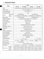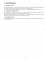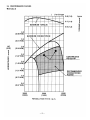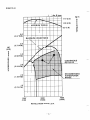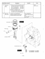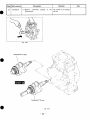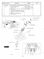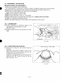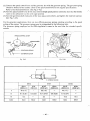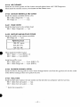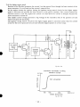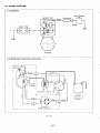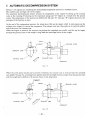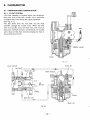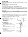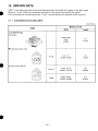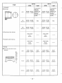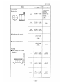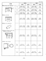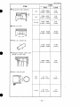
1
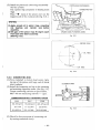
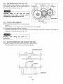
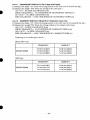
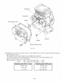
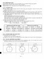
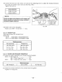
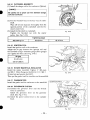
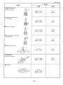
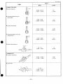
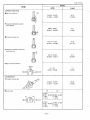
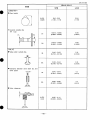
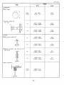
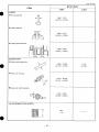
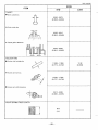
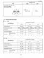
ROBIN AMERICA, INC.
ROBIN TO WISCONSIN ROBIN
ENGINE MODEL CROSS REFERENCE LIST
WISCONSIN ROBIN
ROBIN
0
SIDE VALVE
W 1-080
W1-145
W1-145V
W1-185
W1-185V
W1-230
W 1-280
W 1-340
W 1-390
Wl-45OV
EY21W
EY44W
EY18-3W
EY25W
EY27W
EY08
EY15
EY 15V
EY20
EY2OV
EY23
EY28
EY3 5
EY40 EY45V
EY2 1
EY44
EY 18-3
EY25
EY27
OVERHEAD VALVE
WO1-115
wo1-120
WO1-150
WO1-170
wo1-210
WOl-250
WO 1-300
WO1-300V
WO1-340
WO 1-340V
WO 1-43
OV
EH11
EH12
EH15
EH17
EH21
EH25
EH30
EH30V
EH34
EH34V
EH43V
0
TWO CYCLE
WT1-125V
EC13V
DIESEL
DY23
DY27
DY30
DY35
DY4 1
WRD 1-230
WRD 1-270
-1-300
WRD1-350
WRD1-410
0
NTEN'TS
Section
Title
Page
1
1 SPEClFlCATlONS ............................................................................
PERFORMANCE
............................................................................
4
2.
2-1 Maximum
Output
....................................................................... 4
2-2 ContinuousRatedOutput
..............................................................
4
2-3 M
~ .......................................................................
~
~
~
~ 4
.
2-4
performance
curves................................................................... 5
...................................................................................
4 . GENERAL DESCRlPTlON OF ENGINE COMPONENTS ............................
3. FEATURES
4-1
4-2
4-3
4-4
4-5
4-6
4-7
4-8
4-9
4-10
4-1 1
4-12
4-1 3
4-1 4
4-15
5
.
6.
.
8.
7
8
8
~
.
13-1
13-2
13-3
13-4
13-5
13-6
13-7
"
1. SPECIFICATIONS
~~
~~
~
EH12
Model
EH12B
EH12D
EH12DS
EH12BS
Air-Cooled, 4-Cycle, Single-Cylinder. Horizontal P.T.O. Shaft, Gasoline Engine
TY Pe
60
Bore X Stroke
X
43 mm (2.36
1.57 in.)
121 cc (7.38 cu.in.)
Piston Displacement
8.5
Compression Ratio
Continuous
X
4.0/2000 HP/rpm
4.0 /4000 HP/rpm
2.5/1500 HP/rpm 2.8/1800 HP/rpm
2.5/3000 HP/rprn 2.813600 HP/rpm
1.52/ 1300 kgm/rpm
0.76/2600 kg*m/rpm
output
Max.
Max. Torque
Direction of Rotation
Counterclockwise As Viewd From P.T.O. Shaft Side
Cooling system
Forced Air Cooling
Valve Arrangement
Overhead Valve
Splash Type
Lubrication
Automobile Oil SAE #20, #30 or 1OW-30
Lubricant
Capacity of Lubricant
0.6 liters (0.16 U.S. gal.)
Carburetor
Horizontal Draft, Float Type
Fuel
Automobile Gasoline
Fuel Consumption Rate
230 gr/HP-h At Continuous Rated Output
Fuel Feed System
Gravity Type
Fuel Tank Capacity
3.6 liters (0.95 U.S. gal.)
Ignition System
Flywheel Magneto (Solid State)
NGK B6HS
Spark Plug
i
Charging Capacity
Starting System
Recoil and Electric
Starter
Recoil Starter
Speed Reduction
12V- 1 . 3 ~
Dimensions
1
Recoil Starter
12V- 1.3A
Starter
Recoil and Electric
-
2 1 Cam Shaft Drive
Governor System
Dry Weight
1
Centrifugal Flyweight System
14.5kg (31.91b.)
17.0kg (37.4Ib.)
14.0kg (30.8Ib.)
16.5kg (36.3Ib.)
Length
303mm (11.93in.)
303mm (11.93in.)
301 rnm (11.85in.)
301 mm(11.85in.)
Width
330mm (12.99in.)
345mm (13.58in.)
330rnm (12.99in.)
345mm (13.58in.)
Height
366mm (14.41 in.)
366mm (14.41 in.)
366mm (14.41 in.)
366mm (14.41 in.)
- 1 -
EH17
Model
EH17DS EH17D EH17BS EH17B
Air-Cooled, 4-Cycle, Single-Cylinder, Horizontal P.T.O. Shaft, Gasoline Engine
TY Pe
Bore X Stroke
67
X
Piston Displacement
49 mrn (2.64 X 1.93 in.)
172 cc (10.50 cu.in.)
Compression Ratio
8.5
Continuous
6.0/2000 HP/rprn
output
6.0/4000 HP/rpm
3.5 / 1500 HP/rpm 4.0 / 1800 HP/rpm
I
3.5 13000 HP/rpm 4.0/3600 W r p m
2.1 8 / 1300 kgm/rpm
Max. Torque
1.09 /2600 kg*m/rpm
Counterclockwise As Viewd From P.T.O. Shaft Side
Direction of Rotation
Forced Air Cooling
Cooling system
Valve Arrangement
Overhead Valve
Splash Type
Lubrication
Lubricant
Automobile Oil SAE #20, #30 or 1OW-30
0.65 liters (0.17 U.S. gal.)
Capacity of Lubricant
Horizontal Draft, Float Type
Carburetor
Automobile Gasoline
Fuel
230 gr/ HP-h At Continuous Rated Output
Fuel Consumption Rate
Fuel Feed System
Gravity Type
Fuel Tank Capacity
3.6 liters (0.95 U.S. gal.)
Flywheel Magneto (Solid State)
Ignition System
NGK B6HS
Spark Plug
-
12V - 1.3A
-
Recoil Starter
Recoil and Electric
Starter
Recoil Starter
Charging Capacity
Starting System
I
-
Centrifugal Flyweight System
Governor System
Dry Weight
16.0 kg (35.2 Ib.)
~~~~
Dimensions
Starter
Recoil and Electric
I
I
2:l Cam Shaft Drive
Speed Reduction
1
12V - 1.3A
1
18.5 kg (40.7 Ib.)
I
15.5 kg (34.1Ib.)
I
18.0 kg (39.6 Ib.)
~~
Length
315rnrn (12.40in.)
315mm (12.4Gin.)
313mrn (12.32in.)
313mrn(l2.32in.)
Width
330mrn (12.99in.)
361 mm (14.21 in.)
330mm (12.99in.)
361 rnm (14.21 in.)
Height
380mrn (14.96in.)
380rnm (14.96in.)
380mm (14.96in.)
380rnrn (14.9Sin.)
,-
- 2 -
I-
Model
I
Et125
EH25DS EH25D EH25BS EH25B
1
TY Pe
Air-Cooled, 4-Cycle, Single-Cylinder, Horizontal P.T.O. Shaft, Gasoline Engine
75 X 57 mm (2.95 x 2.24 in.)
Bore X Stroke
251 cc (15.31 cu.in.)
Piston Displacement
Compression Ratio
8.5
Continuous
8.5/2000 HP/rpm
8.5/4000 HP/rprn
5.5/1500 HP/rpm 6.411800 HP/rpm
5.5/3000 HP/rpm 6.4/3600 HP/rpm
3.38 I 1 300 kgWrpm
1.69 / 2600 kg-mlrpm
Output
Max.
Max. Torque
Direction of Rotation
Counterclockwise As Viewd From P.T.O. Shaft Side
Cooling system
Forced Air Cooling
Valve Arrangement
Overhead Valve
Lubrication
Splash Type
Automobile Oil SAE #20, #30 or 1OW-30
Lubricant
1.O liters (0.26 U.S. gal.)
Capacity of Lubricant
Carburetor
Horizontal Draft, Float Type
Fuel
Automobile Gasoline
Fuel Consumption Rate
230 gr/HP-h At Continuous Rated Output
Fuel Feed System
Gravity Type
Fuel Tank Capacity
6.0 liters (159 U S . gal.)
Ignition System
Flywheel Magneto (Solid State)
NGK B6HS
Spark Plug
Charging Capacity
-
12V - 1.3A
12V - 1.3A
~~~
Starting System
Recoil and Electric
Starter
Recoil Starter
Speed Reduction
Dimensions
~~
~~_____
Recoil and Electric
Recoil Starter
-
2:l Cam Shaft Drive
Governor System
Centrifugal Flyweight System
kg (53.9 Ib.)
Dry Weight
24.5
~~
28.5 kg (62.7 Ib.)
24.0
kg
(52.8 Ib.)
28.0(61.6
kg
Ib.)
Length
360rnm (14.17in.)
360mrn (14.17in.)
360rnm (14.17in.)
360mm(l4.17in.)
Width
3 8 5 m m (15.15in.)
405mm (15.94in.)
385mm (15.15in.)
405mrn (15.94in.)
Height
440mm (17.32in.)
440rnm (17.32in.)
440mm (17.32in.)
440mm (17.32in.)
- 3 -
2. PERFORMANCE
2-1 MAXIMUM OUTPUT
A.
The maximum output is the output of an engine with its throttle valve fully opened under the condition
that all the moving parts are properly worn in after the initial break-in period.
A new engine may not produce full maximum output while its moving parts are still not broken-in.
2-2 CONTINUOUS RATED OUTPUT
Thecontinuous rated output is theoutput ofan engine at optimum governedspeedwhich
is most
favorable from the view point of engine’s life and fuel consumption.
i t is recommended that thecontinuousoutput
When the engine is installed on acertainequipment,
required from the engine be kept below this continuous rated output.
2-3MAXIMUM TORQUE
The maximum torque is the torque at the output shaft when the engine is producing maximum output at
certainrevolution.
- 4 -
f
2-4 PERFORMANCE CURVES
0 EH12D, B
(
) for
B type
1 0.8 (1.6)
0.7 (1.4)
-
kg-m
t
I
I
W
MAXIMUM TORQUE
0.6 (1.2)
0
I-
4.0
(2.98 KW)
3.5
(2.61 KW)
3.0
(2.24 KW)
2.5
(1.87 KW)
CONTINUOUS
RETED HP
2.0
(1.49 KW)
1.5
(1.21 KW)
\
1.o
(0.75 KW)
RECOMMENDED
HORSEPOWER
RANGE
0.5
(0.37KW)
2000
(1 000)
3000
(1500)
4000
(2000)
REVOLUTION --s) r.p.m.
i
-5-
0 EHf7D, B
n
(.
). for
B type
"
kg-m
1.I 0 ,(2.2)
1-00 (2.0)
t
I
I
W
Y
0.9 (1.8)
6
CT
0
I-
CoNTiNuous
R E T E 0 HP
RECOMMENDED
HORSEPOWER
\ RANGE
1
REVOLUTION "-+ r.p.m.
-
6 -
0 EH25D, 6
-7-
3. FEATURES
1. The overheadvalve design offersacompactness, light weight and ideal combustioncharacteristics
resulting in more power from less fuel and prolonged engine life.
2. An optimum lubrication and better tilted operation thanks to upright cylinder design.
3. A crossflow arrangement of intake and exhaust ports ensures stable performance under high ambient
temperature.
4. Theautomatic decompressiomsystemlightens
therecoilpull
force by 40% comparing to the
conventional S V engines.
5. An easy operation thanks to integrated engine control system.
6. Combustion and mechanical noises have
been carefully reviewed for better
tonal quality and lower
cnginc noise.
7 . Optimally designed reciprocating parts reduce the
vibration level of the engine. EH25 engine equips
sjnglc through-balancer shaft.
F.
4. GENERAL DESCRIPTION OF ENGINE COMPONENTS
4-1 CYLINDER AND CRANKCASE
The cylinderandcrankcase
is single piecealum i n u m diecasting.Thecylinderliner,made
of
special cast iron, is molded i n t o thealuminum
casting.
Thecrankcase
has 21 mountingsurface
on the
output shaft side, where the main bearing cover is
attached. (See Fig. 4-1 .)
Fig. 4-1
G
-IK
R
i
"
"
"
"
~
CENTERING
OIL GAUGE
OILGAUGE
Fig. 4-2
-8-
/
,
"
4-3 CRANKSHAFT
0
Thecrankshaft
is forgedcarbonsteel,and
the
crank pin is induction-hardened.
Theoutputend of the shafthas a crankshaft gear,
and balancer gear for EH25 which are pressed into
position. (See Fig. 4-3.)
I
B TYPE
1
D TYPE
Fig. 4-3
4-4 CONNECTtNG ROD AND PISTON
The connecting rod is forged aluminum alloy, and
its large and small ends function as bearings. The
piston is analuminum alloycasting,andcarries
two compression rings and one oil ring.
(See Fig. 4-4.)
Fig. 4-4
4-5 PISTONRINGS
The Piston rings are made of special cast iron.
The profile of the top ring is barrel face and
the
second ring has a tapered face with an under-cut.
The oilringconsists of a cutter ring and a coil
expander for better sealing and less oil consumption.
--
TOP RING
SECOND RIN(
OIL RING
r
-9-
4-6 CAMSHAFT
‘I’he camshaft for the D-type engine is made of
special cast iron and camshaftgearsarecasted
togcther in one piece.
Both sides o f the shaft fit into the plane bearings
on the crankcase and main bearing cover.
‘I’hc camshaft for the B-type engine is made of
forged carbon stcel and also functions as PTO
shaft.
The cam gear is pressfitted on the shaft and the
ball bearings arc employed on both sides for supporting the shaft. (See Fig. 4-6.)
I
B TYPE
I
I
D li’PE
Fig. 4-6
4-7 VALVE ARRANGEMENT
‘I’he intake v;llve is located on flywheel side of the
cylinder hcad.
‘I’hc hard alloy v a l v c seatsare
molded i n the
cylinder head andstcllite is fused lo the exhaust
valvc f ; K C .
‘I’hc cylindcr bafflc leads cooling air to the exhaust
valvc arca f o r the optimum cooling. (See Fig. 4-7.)
h
.
Fig. 4-7
4-8 CYLINDER HEAD
‘I’hc cylindcr hcadis
a11 aluminurn die
casting
which utilizcs wcdgc type combustion chamber for
thc highcst combusl.ion cli‘icicncy. (See Fig. 4-13,)
Fig. 4-8
-
10
-
4-9 GOVERNOR SYSTEM
The governor is a centrifugal flyweight type which
ensuresconstantoperation
at theselectedspeed
against load variations.
The governorgear with governorweightsis
installed on the main bearing cover. (See Fig. 4-9.)
/
GOVERNOR GEAR
Fig. 4-9
4-10 COOLING SYSTEM
The large fins on the flywheel provide sufficient cooling air capacity for
cylinder.
The cylinder baffle helpsthe cooling air flow efficiently.
the inlet and exhaust area and
4-11 LUBRICATION
All the rotating and slidingpartsaresplashlubricated by the oil scraper on the connecting rod.
(See Fig. 4-10.)
1‘
I
OIL SCRAPER
Fig. 4-10
- 11 -
4-12 IGNITION SYSTEM
The ignition system is a transistor
controlled
of a flymagneto ignition systemwhichcosists
wheel and a n ignition coil with a built in transistor.
Thissystem has an ignition timingadvance for
easy starting. (See Fig. 4-1 1.)
Fig. 4- 1 I
4-13 CARBURETOR
The enginesareequippedwith
a horizontal draft
carburetor that has a float controlled fuel system
and a fixed main jcl.
The carburetors are calibratedcarefully for easy
starting, good acceleration, low fuel consumption
and sufficient output.
For datails, see page 47, section 8.
“CAKBUKE‘I’OR”. (SCCFig. 4-12.)
4-14 AIR CLEANER
‘I’hc air clcancr is a single urcthine foam element system. As an option, heavy duty type with a double
elemcnI type is available. (See Fig. 4-13-1 and 4-13-2.)
COVER
_ _.
Double element type
Single element type
”
~.~
~
Fig. 4- 13-2
Fig. 4- 13-1
-
12 -
/”
4-15 SECTIONAL VIEW
OF ENGINE
FUEL TANK
/
I
I
/
FLYWHEEL
-
13
-
II
+
.PISTON
MAIN BEARING COVER
ROCKER ARM
I
L
-
14 -
5.
5-1 CAUTIONS
1) Because some matingpartswithwear
surfaces weremachinedtogether
when the enginewas
manifactured, or have established wear patterns during operation, the reassembly of engine parts, is
critical to the performance and life expectancy of the engine. MARK AND SORT ALL PARTS SO
THAT THEY WILL BE DISASSEMBLED AND INSTALLED IN THEIR ORIGINAL POSITIONS.
2) Crankshaft and camshaft bearings should be cleaned
and inspected, and removed only if they appear
or
to be damaged or excessively worn. Remove bearings that are pitted, nicked, burred, discolored,
that rotate roughly or noisily.
3) Keepcleanandhandlecarefullythedisassembledparts,Cleanthemthoroughlywithwashingoil
before the reassembly.
4) Use correct tools in the proper way
The use of non-specified tools could cause permanent damage to the engine or components.
5-2 SPECIAL TOOLS
Tool
Tool No.
209- 95004- 07
Market parts
Use
Flywheel puller with bolt
For pulling off the flywheel Eli17,EH25
Flywheel puller
For pulling off the flywheel EH12
FLYWHEEL PULLER
FLYWHEEL PULLER
-
15 -
5-3 DISASSEMBLY PROCEDURES
Step Part to remove
I
Oil drain
Procedures
Remarks
( I ) Remove oil drain plug and drain oil.
(2) ‘To discharge oil quickly,
remove
oil
gauge.
Be careful not to lose the
gasket.
GASKET
I
14mm box wrench
DRAIN PLUG
Fig. 5-2
-
Tool
16 -
step Part to remove
2
Fuel tank
Procedures
Tool
Remarks
Wipe off spilt fuel
(1) Close fuel valve.
(2) Disconnect fuel hose between fuel strainer thoroughly.
and carburetor.
( 3 ) Remove fuel tank from cylinder head.
M6X14rnm bolt
4pcs. (EH12,17)
M8X20mm bolt
4pcs. (EH25)
....
.-..
lOrnrn (1 2mm)
socket wrench
M6 BOLT : 4 pcs.(EH12,17)
ME BOLT : 4 pcs.(EH25)
FUEL HOSE
- 17-
I
I
Step Part to remove
1
I
Procedures
~~
3
Recoil starter
Remarks
Tool
( I ) Remove recoil from blower housing.
M6 X8mm flange bolt
4pcs.
lOmm box wrench
Blower
housing
( I ) Remove blower housing from crankcase.
M 6 X I 2 m m flange bolt
4pcs.
lOmm box wrench
Oil scnsor
(Option)
( 1 ) Remove oil sensor probe. Be careful not
- . a -
4
5
- e
-.
to damage stick and sensor since these are
sensitive and an erratic operation may
result.
Fig. 5-4
- 18-
Step
'art to removc
6
Muffler cover
Muffler and
Muffler
bracket
Procedures
(1) Remove muffler cover.
Remarks
Tool
Be careful not to lose
3pcs.
M 5 x lOmm flange bolt
muffler gasket.
(EH12,17)
M5 X lOmm flange bolt
4pcs. (EH25)
(2) Remove muffler from exhaust manifold.
M8 flange nut -. 2pcs.
( 3 ) Remove muffler bracket from crankcase.
M6X 12mmflangebolt
lpc. (EH12,17)
M8X16mmflangebolt
lpc. (EH25)
8mm, lOmm and
12mm socket wrench
(1) Remove manifold cover from manifold.
M6X8mm flange bolt
Ipc.
M8 flange nut
2pcs.
(2) Remove manifold from cylinder head.
IOmm, 12mmsocket
wrench
....
--
--
....
e...
7
Exhaust
manifold and
Manifold
cover
....
....
- 19 -
Be
careful
not to
lose
muffler gasket.
Step Part to remove
a
Control box
and Electric
starter
(Option)
Procedures
Remarks
Tool
( I ) Disconnect wires.
1 (diode rectifier )
blue
light blue
I (diode rectifier )
black
I (magnetic switch)
(2) Remove black wires from electric starter.
(3) Remove control box.
Fastened together with
fuel tank.
(4) Loosen two flange bolts and remove
electric starter.
M8 flange bolt
2pcs.
M 8 FLANGE BOLT : 2 pcs.
/’
\
,/
ELECTRIC STARTER
Fig. 5-6
- 20
-
12mm socket wrench
I
Step
remove
to
Part
I
Procedures
Remarks
Tool
~~~~
9
Head cover
( 1 ) Remove head cover from crankcase.
M6x 12mrn flange bolt
Ipc.
10
Air cleaner
(1) Removecleanercover,cleaner
I Ornm
socket wrench
-.--
element
and element retainer.
(2) Remove cleaner case.
M6 flange nut -..-2pcs.
GASKET
Fig. 5-7
-
21
-
Fastened together with
carburetor.
CLEANER CASE
1Omm
socket wrench
I
Step Part to remove
Procedures
Remarks
governor spring from speed
control lever.
(2)Removegovernorlever
from governor
shaft.
M6X30mm bolt and washer
Ipc.
(3) Detach governor lever, governor rod and
rod spring from carburetor.
Bolt and washer on
governor
lever
only
needs to be loosened.
11
12
Governor
lever,
Governor rod
and Governor
spring
14
-
lOmm
socket wrench
- - - a
I
Carburetor
~
13
( 1 ) Unhook
Tool
I
( 1 ) Removecarburetor from intake manifold.
~~
~
~~
~~~
I
lOmm
socket wrench
Speed control
lever
( 1 ) Remove stop plate, friction plate and
I n take
manifold
( I ) Remove intake manifold from cylinder
head.
M6 flange nut
2pcs. (EH12,17)
M6X25mmflangebolt.... lpc. (EH12,17)
M8x28rnm bolt and washer
~ P C S (EH25)
.
speed control lever.
M6X30mmflangebolt
I
~
--..lpc.
.---
Be
careful
not to lose
insulator and gasket.
lOmm, 12mm
socket wrench
* * a .
~~
~
~
M6 FLANGE BOLT : 1 PC.
~~~
~
~
~~~
~
9-
STOP PLATE
./a
/“I”.
M6 FLANGENUT : 2 pcs(EH12.17)
M6 FLANGE BOLT : 1 pc(EH12.17)
GASKET
M6 BOLT and WASHER : 3 pcs.
(EH25)
FRICTION PLATE
(INSULATOR)
A
SPEED CONTROL LEVER
,-\
ROD SPRING
GOVERNOR LEVER
.
’
M6 BOLT and WASHER : 1
PC.
Fig. 5-8
- 22 -
Procedures
15
Starter pulley
Remarks
Tool
(1) Remove starter pulley from flywheel.
Do not place bar or screw
Place socketwrench on flywheel fastening driver in flywheel fin to
nut and strike tip of the lever with loosen flywheel nut.
hammer. Refer to the illustration below.
(See Fig. 5-9.)
14mm nut
lpc.
(EH12,EH17)
18mm nut
lpc. (EH25)
M6 X 14mm flange bolt
1pc. (EH2.5)
-.-.
19mm (EH12,17)
24mm (EH25)
socket wrench
--
~~
16
1
Flywheel
(1) Remove flywheel from crankshaft.
Charge coil
(Option)
(1) Remove charge coil.
(2) Remove key from crankshaft.
(See Fig. 5-1 1.)
Use
flywheel
puller as
illustrated below.
(See Fig. 5-10.>
I
17
M6 X 20mm Screw
2pcs.
w
Fig. 5-9
Fig. 5-10
FLYWHEEL
Fig. 5-12
- 23 -
~~
Flywheel puller
Step Part to remove
~~
18
Ignition coil
1
I
Procedures
~
~~
( I ) Disconnect ignition plug cap and remove
ignition coil from crankcase.
M6 X 25rnm bolt and washer
Tool
Remarks
1 Omrn
socket wrench
- - -.2pcs.
19
Spark plug
( I ) Remove spark plug from cylinder head.
21 rnrn
socket wrench
20
Breather
( 1 ) Remove breather cover.
1 Ornrn
socket wrench
M6 X 20mm flange bolt
-
2pcs.
(2) Remove gasket (breather cover), breather
plate and gasket (breather plate).
iGNlTiON COIL
M6 BOLT and WASHER : 2 pcs.
GASKET (BREATHER COVER)
BREATHER COVER
M6 FLANGE BOLT : 2
Fig. 5-13
-
24 -
pCS.
I
Step Part to remove
Procedures
Rocker
(1) Remove rocker cover from cylinder head.
21
M6X
12mm
flange
bolt
4pcs.
( 2 ) Remove gasket. (rocker cover)
22
-
Cylinder head
(1) Remove cylinder head from crankcase.
M8X65mm flange bolt
4pcs.
L
M6 FLANGE BOLT : 4 pcs.
- 25
-
lOmm
socket wrench
socket wrench
(EH12,17)
MlOX75mmflange bolt.... 4pcs. (EH25)
(2) Detach cylinder head gasket from cylinder
head.
( 3 ) Remove push rods.
/
Tool
12rnm, 14mm
.+..
L
Remarks
Step Part to remove
23
Main bearing
cover
1
Procedures
Remarks
Be careful not to damage IOmrn, 12rnrn
socket wrench
oil seal.
( I ) Remove
mainbearingcoverfastening
bolts.
M6X30mm bolt and washer
8pcs.
(EHI2,17)
M 8 X 30mm bolt and
washer
. - - e
8pcs.
(EH 25)
(2)
Tool
Remove main bearing cover using plastic
hammer. (See Fig. 5-15)
Fig. 5-15
-
26
-
Step Part to remove
I
Procedures
Remarks
24
Cam shaft add ( I ) Remove cam shaft from crankshaft.
Balancer shaft (2) Remove balancer shaft. (EH25 only)
(EH25 only)
To prevent tappetsfrom
gettingdamaged, put the
crankcase upsidedown.
(See Fig. 5- 17.)
25
Tappet
Put a tag on tappets to
identify intake and
-
(1) Remove
tappets
from
crankcase.
I
exhaust.
- 27 -
Tool
Step Part to remove
26
Connecting
rod and
Piston
Remarks
Procedures
.....
.. .
... .
.
"
. ..
.
Tool
.. .
lOmm
socket wrench
( 1 ) Remove connecting rod bolt after scraping
off carbon from cylinder head and piston.
M6 X 34mm flange bolt
2pcs. (EH 12)
2pcs. (EH17)
M7X37mm flange bolt --.2pcs. (EH25)
M8X46mm flange bolt
(2) Remove connecting rod cap.
(3) Removeconnecting rod fromupperside
of crankcaseafter rotating crankshaft so
that piston comes up to top dead center.
----
....
27
Piston and
Piston riugs
Do not damage the.
smaller end of connecting
rod.
Do not expand or twist
piston rings.
( I ) Remove clips and piston pin.
(2) Remove piston from connecting rod.
( 3 ) Remove piston rings from piston.
M6 FLANGE BOLT : 2 pcs. (EH12)
M7 FLANGE BOLT : 2 pcs. (EH17)
M8 FLANGE BOLT : 2 pcs. (EH25)
Fig. 5-19
-
28
-
Procedures
Step Part to remove
28
Crankshaft
Remarks
( I ) Remove
crankshaft
tapping
flywheel end.
at
the
Fig. 5-20
CRANKSHAFT (D type)
fig. 5-21
- 29 -
Be careful not to damage
oil seal.
Tool
Step Part to remove
Procedures
29
Intake valve
and Exhaust
valve
Tool
Remarks
"
~~~~
( 1 ) Loosen adjusting screw on rocker arms.
Inspect
valves,
valve
seats and guide.
Do not remove
valve
guides unless they are
worn beyond the limit
shown in page 57.
(2) Pull out rocker arm shaft from the intake
side of the cylinder head.
(See Fig. 5-22.)
(3) Remove
rocker
arms
after
removing
rocker shaft.
(4)Press down spring retainer and slide it to
releasefrom the groove of valvestem,
then remove spring retainer and valve
spring
(5) Remove intake and exhaust valve.
(See Fig. 5-23.)
SCREW
ROCKER ARM
DCS.
ROCKER SHAFT
SPRING RETAINER
VALVE SPRING
I
INTAKE VALVE
II
Fig. 5-24
I
\
Fig. 5-23
- 30 -
5-4 REASSEMBLYPROCEDURES
0 PRECAUTIONS FOR REASSEMBLY
1)Clean parts throughly before reassembly.
Pay most attention to cleanliness of piston, cylinder, crankshaft, connecting rod and bearings.
2)Scrape off all carbon deposits from cylinder head, piston top and piston ring grooves.
3)Check lip of oil seals. Replace oil seal if the lip is damaged.
Apply oil to the lip before reassembly.
4)Replace all the gaskets with new ones.
5)Replace keys, pins, bolts, nuts, etc., if necessary.
6)Torque bolts and nuts to specification referring to the “TORQUE SPECIFICATIONS”.
7)Apply oil to rotating and sliding portions.
8)Check and adjust clearances and end plays where specified in this manual.
54-1 CRANKSHAFT
(1) Installcrankshaft on crankcase using an oil
seal guide to avoid damage to oil seal.
(See Fig. 5-26.)
(2) Install woodruff key for the flywheel on crankshaft.
Fig. 5-26
5-4-2 PISTON AND PISTON RINGS
(1) Installthe oil ring first, thensecondringand
top ring.
Spread the ring only far enough to slip over
piston and into the correct groove. Use care
to distort the ring. (See Fig. 5-27.)
Install the top ring and the second ring with
punched mark “N” beside the gap on the
side. (See Fig. 5-29.)
OPEN ENDS OF PISTON RING
I
the
not
the
top
Fig. 5-27
- 31 -
“N”
MARK
TOPRING
SECOND RlNC
OILRING
I
Fig. 5-28
Fig. 5-29
5-4-3 PISTON AND CONNECTING ROD
(1) When installing the piston on the connecting
rod, place ‘‘4” mark of the piston crown on
the “MAG” side of the connecting rod.
(See Fig. 5-30.)
Apply oil to the small end of the connecting
rod, piston and piston pin before installation.
Be sure to use clips on the both end of the
piston pin to secure the pin in position.
“MAG” SIDE
I
”
Fig. 5-30
-
32 -
4
”
MARK
(2) Install the piston and connecting rod assembly
into the cylinder.
Use a piston ring compressor to hold the piston
rings.
Place ‘‘4” mark of the piston crown on the
magneto side of the crankcase.(See Fig. 5-31.)
-[NOTES]
PISTON RING COMPRESSOR
CONNECTING ROD
1
(1) Applyenough
oil to piston rings, connecting
rod
bearings
and
cylinder
bore
before
assembly.
(2) Set gaps of the piston rings 90 degrees apart
from each other before assembly.
(See Fig.5-32.)
CRANK CASE (FLYWHEEL SIDE)
Fig. 5-31
-SECOND
\
Fig. 5-32
5-4-4 CONNECTING ROD
(1) Turn crankshaft to bottom dead center, lightly
tap top of the piston until large end of the rod
meet crankpin.
( 2 ) Install the connecting rod cap to the connecting
rod matching alignment marks. (See Fig. 5-33.)
Torque connecting rod bolts to specification.
M8 X 46 mm connecting rod bo1t
2pcs.
ALIGNMENT MARK
h
....
CONNECTING ROD BOLT TIGHTENING TORQUE
I
EH12
90-1 15 kg*cm
9-11 N-m
6.5-8.3 ft*lb
B
I
EH17
170-200 kg-cm
17-19.5 Nom
12.3-1 4.5 ftdb
I
I
EH25
225-275 kgocrn
22-27 Nom
Fig. 5-33
16.3-19.9 ft4b
(3) Check for free movement of connecting rod
by turning crankshaft slowly.
-
33
-
RING
54-5
BALANCER SHAFT (EH25 type only)
Install balancer shaft aligning the timing mark
thebalancershaftgear
and thebalancergear
the crank shaft as shown in Fig. 5-34.
on
on
Incorrect
timing
of the
gears
will
cause
result in
malfunction
of
the
engine
and
may
damage due to interference of the
parts.
TIMING MARKS
5-4-6 TAPPET AND CAMSHAFT
Fig. 5-34
(1) Oil the tappets and install them in their original
position.
Push in fully to avoid damage during the installation of the camshaft.
(2) Lubricate the bearing surfaces of camshaft.
Align the timing mark on the crankshaft gear with the timing mark on the camshaft and install the
camshaft in the crankcase. (See Fig. 5-36.)
Incorrect
valve
timing
malfunction.
will
cause
engine's
5-4-7 ADJUST CRANKSHAFT AND CAMSHAFT END PLAY
( 1 ) Adjust end play to the specified values using the proper spacer.
The proper spacer may be determined following manner.
MAIN BEARING COVER
A1
c
t
A2
f
GASKET
I
Fig. 5-35
-
34 -
CRANKCASE
CRANKSHAFT END PLAY (For D type and B type)
(1) Measure the depth “ A l ” (From the mating surface to the inner race of the ball bearing.)
(2) Measure the height “BI” (From the mating to the crank gear.)
( A l + 0.3) - Bl=SIDE CLEARANCE (mm)
(SIDE CLEARANCE) - 0.2=THICKNESS OF CRANKSHAFT SHIM (mm)
(A+ 0.0123 Bl=SIDE CLEARANCE (in)
SIDE CLEARANCE - 0.008”=THICKNESSO F CRANKSHAFT SHIM (in)
5-4-7-1
-’
5-4-7-2
CAMSHAFT END PLAY (Model B=2:1 Reduction type only)
(1) Measure the depth “A2” (From the mating surfaceto the inner race of the camshaft bearing.)
(2) Measure the weight “B2” (From the mating surface to the camgear inner boss.)
(A2+ 0.3) - B=SIDE CLEARANCE (mm)
(SIDE CLEARANCE) - 0.2=THICKNESS OF CAMSHAFT S H I M (mm)
(A2+ 0.012”) - B=SIDE CLEARANCE (in)
SIDE CLEARANCE - 0.008”=THICKNESS O F CAMSHAFT SHIM (in)
Following are availalbe spacer shims.
EH12, EH17 type
CRANKSHAFT
SPACER SHIMS
T=0.6 mm (0.024”)
T=0.8 mm (0.031”)
T=l .O mm (0.039”)
CAMSHAFT
T=0.6 mm (0.024”)
T=0.8 mm (0.031 ”)
T=l.O mm (0.039”)
EH25 type
CRANKSHAFT
SPACER SHIMS
T=2.7 mm (0.106”)
T=2.9 mm (0.114”)
T=3.1 mm (0.112“)
- 35 -
CAMSHAFT
T=0.6 mm (0.024”)
T=0.8 mm (0.031”)
T=l .O m m (0.039”)
Fig. 5-36
(2) Lubricate the oil seal and bearing surfaces. Add a light film of oil on the main bearing cover face to
hold the gasket in place.
Place spacers chosen at procedure (1) on cTankshaft and camshaft.
U s e an oil seal guide when installing the main bearing cover to avoid damaging the seal.
Tap the cover into place with a soft hammer.
Main bearing cover E1412, 17 M 6 X 30 mm bolt and washer -... 8 pcs.
Et4 2s
M 8 X 30 m m bolt and washer
8 pcs.
....
Tightening torque (EH12,17 type) Tightening torque (EH25 type)
.
80-1 00 k g c m
170-1 90 k g w n
8-9.5 Nom
17-1 8.5 Nom
6-7 ft*lb
1
12.5-13.5 ft4b
I
- 36
-
5-4-8 BREATHERVALVE
Attach breather plate (breather valve) and breather cover to crankcase usingproper gaskets.
Replace gaskets with new ones if they are torn or damaged.
Replace breather hose at least once a yearor when ever a crack was found.
W
5-4-9 CYLINDER HEAD
(1) Clean carbon and gum deposits from the valves, seats, ports and guides.
Inspect the valves, valve
seats and valve guides.
(2) Replace valves that are badly burned, pitted or warped.
(3) When installing the valvesin the cylinder head,oil the valve stems and insert
them into the valve guide.
Then place the cylinder head on a flat table, install the washer, valve spring and spring retainer.
(4) Valveguidesshouldbereplacedwhenthevalve
stem clearanceexceedsspecifications
(See
"SERVICE DATA").
Draw the valve guides out and press thenew guides in.
Refer to"SERV1CE DATA"for clearance specifications.
After replacing the valves and guides, lap valves in place until a uniform ring shows around the face
of the valve. Clean valves and wash cylinder head thoroughly.
( 5 ) Install cylinder head to cylinder with new head gasket.
Tighten five flange bolts evenly in three steps by the following tightening torque:
Cylinder head M 8 X 65 mm flange bolt . - - -4- pcs. (EH12, 17)
M10 X 75 mm flange bolt .... 4 pcs. (EH25)
I
~~~
~
~~~
I I
Tightening
torque
(EH12, EH17 type)
2nd step
1st step
50 k g c m
100 k g c m
5 Nom
10 Nom
I
Tightening
torque
(EH25 type)
1st step
2nd step
final step
I
I
I
I
7.2 ft*lb
3.6 fblb
5-4-10 ROCKER ARMS AND PUSH RODS
(1) Insert push rods into crankcase.
Put push rod tip in the hollow of tappet top.
(2) Apply oil to the rocker arms and assemble them to the cylinder head using the rocker shaft and spacer.
5-4-11 VALVECLEARANCEADJUSTMENT
(1) Position the piston at the top dead center of the compression stroke.
obtained by placing the key slot on the power take of€ shaft to :
I
I
12 o'clock
10 o'clock
EH I2B, I7B, 25D
EH25B
!
_I
I
i
(J
1.-
I
Fig. 5-37
- 37
-
T h e top dead center may be
EH I2D,17D
(2) Loosen the lock nut on the rocker arm and turn the adjusting screw to adjust the clearance between
the rocker arm and the valve stem end. (See Fig. 5-38.)
Tighten the lock nut.
I
I
clearance
Valve
I
0.085-0.1 15 rnm
[NOTE]
Check and adjust valve clearance with engine
coid.
Check operationof.valves by turning crankshaft.
Remeasure tappet clearance.
(3) Install rocker cover and gasket.
Rocker cover M 6 X 12 m m bolt
- - - - 4 pcs.
5-4-12 SPARK PLUG
Install spark plug to the cylinder head.
Spark plug :
EH12
: N G K B6ES /CHAMPION N5C
E H 1 7 , 2 5 : N G K B6HS /CHAMPION L86C
Tightening toque
New spark plug
120-1 50 kg*cm
Retightening
230-270 kgcm
11.8-14.7 Nom
22.6-26.5 N-m
8.7-10.9 ft*lb
16.6-1 9.5 ft*lb
I
5-4-13 INTAKE AND EXHAUST MANIFOLD
( I ) Install the intake manifold to the cylinder head with gasket.
EH12, 17 M 6 flange nut .................. .. 2 pcs.
M 6 X 25mm flange bolt ----...-1 PC.
I%25
M 8 X 28mm boltand washer - - 3 pcs.
--
Tightening toque
100-1 40 kg-cm
7.2-1 0.1 ft*lb
9.8-1 3.7 N*m
( 2 ) Install the exhaust manifold to t h e cylinder head with gasket.
Tighten two flange nuts.
-
38 -
B
5-4-14 FLYWHEEL MAGNETO
(1) Install the charge coil to the crankcase. (Option)
- [NOTE)
Be careful not to pinch coil wire between charge
coil and crankcase.
(2) Put the woodruff key in the key way of crankshaft.
Wipe off oil and degrease thoroughly from the
taperedportion of the crankshaft and the flywheel center hole.
(3) Install the flywheel to crankshaft.
Tighten
the
flywheel
nut with the
starter
pulley. (See Fig. 5-39.)
I
I
Fig. 5-39
Tightening toque
59-63 Nom
600-650 kg*cm
43-47 ft*lb
5-4-15IGNITIONCOIL
Install the ignition coil to the crankcase.
gap between the ignitioncoiland
the flywheel using a thickness gauge (filler gauge)
and tighten the bolts. (See Fig. 5-40.)
Adjust theair
I
Air gap
0.3-0.5 mm
I
0.012-0.020 in.
5-4-16INTAKE
MANIFOLD, INSULATOR
Installtheintakemanifold.Tighten
2 - M 6 nuts
and M 6 X 25mm flange nut for EH12,17,3- M 8 X
28 mm bolt and washer for EH25.
Then put the gasket and the insulator on the manifold.
Fig. 5-40
5-4-17
CARBURETOR
Install the gasket and the carburetor to the manifold.
5 4 - 1 8 GOVERNOR SYSTEM
(1) Connectthegovernorlever
and the throttle
lever on carburetor.
Install
the
governor lever on the
governor
shaft. (See Fig. 5-41.)
(2) Install the speed control lever
to the cylinder
head.
GOVERNOR LEVER
Fig. 5-4 1
- 39 -
(3) Connect the speed control lever and the governor lever with the governor spring. The governor spring
should be hooked to the number 2 hole on the speed control lever for the regular specifications.
Refer to the illustrations below. (See Fig. 5-42.)
(4) T u r n the speed control lever all the way toward the high speed position and make sure that the throttle
valve in the carburetor is at the wide open position.
( 5 ) Turn t h e governor shaft clockwise all the way using a screw driver, and tighten the lock bolt and nut.
(See Fig. 5-43.)
P\
For the generator applications, there are two different governor springs existing according to the speed
setting of the engine. The governorsprings may be distingnished by the following table.
The governor spring employed on the 6OHz application is same as the one from the standard specifications.
SPEED CONTROLLEVER
GOVERNOR SPRING
\\
f-
GOVERNOR LEVER
Fig. 5-42
Fig. 5-43
N ; SPRING WOUND
Et 12
EH17
EH25
60 Hz
(3600 rpm)
50 HZ
(3000 rprn)
60 Hz
(3600 rprn)
t
43 (1.7")
t
10.7 (0.42")
9.6 (0.38")
8.7 (0.34")
c
t
8.5
t
19.5
16.5
Silver
Gold
Silver
Gold
Silver
50 Hz
(3000 rpm)
60 Hz
(3600 rpm)
Q
49 (1.9")
t
D
9.1 (0.35")
8.1 (0.32")
N
12.5
Color
Gold
50 HZ
(3000 rpm)
38 (1 5")
P
-
40 -
rn
@
5-4-19 AIR CLEANER
Install the air cleaner gasket and the cleaner case and tighten them with2-M6 flange nuts.
Then install the element retainer, the element and the cleaner cover.
5-4-20 EXHAUST MANIFOLD AND COVER
Install the exhaust manifold and the cover.
-
M 6 X 8mm flange bolt ... 1 PC.
M 8 flange nut . . . . . f . - . - - - -2- pcs.
5-4-21HEADCOVER
Install the head cover to the cylinder head.
M 6 X 12mm flange bolt
1 PC.
----
5-4-22 MUFFLER AND MUFFLER COVER
Install the muffler to the exhaust manifolde
M 8 flange nut
2 pcs.
.---
I
Tightening torque
230-270 kg-crn
I
22.5-26.5 N a r n
16.6-1 9.5 ft*lb
Then installthemuffler bracket.
M 6 X 12mm
1 PC. (EH12, 17)
M8 X 16mm
1 PC. (EH25)
------ -
Install the muffler cover
M 5 X lOmm screw *..-..--.
3 pcs. (EW12, 17)
M 6 X lOmm flange bolt .... 4 pcs. (EH25)
5-4-23 BLOWER HOUSING,RECOIL
Install the blower housing and the recoil. Insert the high tension cord from the ignition coil into the notch
of the blower housingso that not to pintch the cord.
5-4-24FUELTANK
Install the fuel tank. Connect the fuel strainer and the fuel inlet on carburetor with the fuel hose.
M 6 X 14mm bolt and washer
1 PC.
M 8 X 16mm bolt and washer .--.1 PC.
---.
-
End-of the reassembly
-
- 41
-
5-5 BREAK-INOPERATION
An enginethathas
been completelyoverhauled by beingfitted with a new piston,rings, valves and
R U N - IN before
being
put back into service.
connecting rod should
throughly
be
Good bearing surfacesand r u n n i n g clearancesbetweenthevariouspartscan
only beestablished by
operating the engine under reduced speed and loads for a short period of time.
While the engine is being tested, check for oil leaks.
Make final carburetor adjustment and regulate the engine operating speed.
Load
Engine speed
Time
Step 1
No load
2500 rpm
10 rnin
Step 2
No load
3000 rpm
10 min
Step 3
No load
3600 rpm
10 min
3600 rpm
30 min
3600 rpm
60 min
Steps
Step 4
Step 5
EH12
EH17
1.4
2.0
EH25
3.2
EH12
EH17
2.8
4.0
EH25
6.4
/“
6. IGNITION SYSTEM
6-1 TYPE OF IGNITION SYSTEM
EH 12 employs the U . T . C. I. (Universal type Transistor Controlled Ignition) pointless ignii.ion system.
El417 and E 3 2 5 have the T . I. C. (Transistor Controlled Ignition) pointless ignition system.
As optional parts, these ignition system m a y be implemented with lamp coil, charge coil and excitor coil.
6-2 BASIC THEORY
‘1’0 ensure the easy startability of the engine, the step advancing ignition timing system is incorporated in
the ignition coil. ‘I’his system enables the engine to havebasicallytwodifferentignitiontimings
according to the engine spced. Following are the explanation how the system works.
1 ) At lower speed of the engine
I , , as this currentflows through thebaseterminal
of the
Kotation of the flywheelinducescurrent
power transister, it is activated and the current Lz starts flowing.
As thc cnginc reaches thc ignition timing, the ignition timing control circuit for the lower engine speed
is activated and lcts the current I,: flow through the base terminal of the power transistor.
‘l’his gcncrates the collcctor current I, which will bypass the current I, and abruptly s h u t off the current
I? because the powcr transistor is turned off.
‘I’his suddencurrentchangegenerates
a bigvoltage on thesecondaryside
of theignitioncoil
and
which sparks thc spark plug.
- 42 -
/”--
2) At the higher engine speed
Rotation of the flywheel generates the current I, as this current flows through the base terminal of the
power transistor, i t is activated and the current IZ starts of flow.
As the enginereaches the ignitiontiming, the ignitiontimingcontrolcircuit
for the higher engine
speed is activated and provides the base current
Is to the power transistor. This current induces the
coIlectorcurrent 16 and will bypass the current I, to shutdown the current I r abruptlybecausethe
power transistor is turned off.
Thissuddencurrentchangegeneratesabigvoltage
on the secondaryside of the ignitioncoil and
which will spark the spark plug.
The ignition timing control circuit
for thehigherenginespeed
is activated sooner than the control
circuit €or the lower speed and not activated when the engine speed is in a lower range.
ELECTRONIC ADVANCING FLYWHEEL
MAGNETOSYSTEM
(B.T.D.C.)
L
STEP ADVANCING
15'1
,
,
,
500
1000
2000
ENGINEREVOLUTION
Fig. 6-2 ( b )
-
43
-
,
3000(r.p.m.)
6-3 WIRING DIAGRAM
1
STANDARD
-
StopButton
Ignition Coil
Connector
Spark Plug
r=+
TfT
Flywheel
ElNGlNE WITH ELECTRIC STARTER
I
w
3
_1
m
-
KEY
MAGNETIC SWITCH
L"""
SWITCH
-1
12VOLT
BATTERY
MINIMUM 24
AMP.HR.
I """"""""-
U
I
DIODE RECTIFIER
I
Fig.
6-3
- 44 -
7 . AUTOMATIC DECOMPRESSION SYSTEM
’
EH12, 17, 25 engines are employing the automatic decompression system as a standard feature.
This enables easy and light start of the engine.
The automatic decompression system releases the compression of the engine by lifting up the exhaust
valve at the cranking. Following are the explanation using type “D” engine as a sample how the system
works. The components of the systems are different for the type “D”and type “B” engines, however, the
principle of the function is same.
At the end of the compression process, the release lever lifts up the tappet which in turns opens up the
exhaust valve slightly to release the compression. The release lever has a flyweght on its end and another
end of the lever is a crescent cam.
lifts up the tappet
When the engine is cranked, the crescent cam projects the camshaft cam profile and
because the gravity force on the weight is larger than the centrifugal force on the weight.
LEVER
CRESCENT
EXHAUST
‘7
CAMSHAFT
Fig. 7-1
When the crank speed reaches up to a certain revolution, the crescent cam is retracted into the camshaft
cam profile because the centrifugal force applied onto the flyweight becomes larger than the gravity force
and the weight and is shifted to the position shown in the illustration.
FLYWEIGHT
LEVER
Fig. 7-2
- 45 -
8. CARBURETOR
8-1 OPERATIONANDCONSTRUCTION
/"
8-1-1 FLOAT SYSTEM
Thefloatchamber
is locatedbelowthecarburetor
body and, with a float and a needle valve, maintains
a constant fuel level during the engine operation.
(See Fig. 8-1.)
The fuelflows
from the fuel tankintothefloat
chamber throughtheneedle
valve. When thefuel
rises to a specific level, the float rises, and when its
buoyancy and fuel pressure are balanced, the needle
at
valve shuts off the fuel, thereby keeping the fuel
the predetermined level.
\
PILOT OUTLET
- - - - -a=-
B Y - PASS,,
I
I
--
AIR
INTAKE
!
MAIN AIR JET
-
46 -
0
8-1-2 PILOT SYSTEM
The pilot system feeds the fuel to the engine during idling and low-speed operation.
The fuel is fed through the main jet to the pilot jet, where it is metered, and mixed with the air metered
by the pilot air jet.
The fuel-air mixture is fed to the engine through the pilot outlet
and the by-pass.
At the idling speed, the fuel is mainly fed from the pilot outlet.
8-1-3 MAIN SYSTEM
The main system feeds the fuel to the engine at medium-and high-speed operation.
The fuel is metered by the main jet and fed to the main nozzle. The air metered by the main air jet
is
mixed with the fuel through the bleed holes in the main nozzle, and the mixture
is atomized out of the
main bore, It is mixed again with the air taken through the air cleaner into an optimum fuel-air mixture,
which is supplied to the engine.
8-1-4 CHOKE
The choke may be used for easy start when engine is cold. When the engine is cranked with a closed
draws more fuel accordingly this
choke, the negative pressure applied to the main nozzle increases and
starting up the engine more easily.
8-2 DISASSEMBLY AND REASSEMBLY
Apartfrommechanical
failures, most of carburetortroublesarecaused
by an incorrect mixing ratio,
which may arise mainly due to a clogged up air or fuel passage in jets, or fuel level variations. In order to
assure properflow of air andfuel, the carburetor must be keptclean at all times.Thecarburetor
disassembly and reassembly procedures are as follows : (See Fig. 8-3.)
8-2-1 THROTTLE SYSTEM
(1) Remove the philips screw (1) and throttle valve
( 2 ) , and pull out the throttle shaft (3).
(2) The spring (4) can be taken out by removing the
throttle stop screw(5).
* Be careful not to damage the throttle valve rim.
8-2-2 CHOKE SYSTEM
(1) Removethephilips
screw (6) and chokevalve
(7), and pull out the choke shaft (8).
( 2 ) When reassembling thechokeshaft,make
sure
that the cutout in the choke valve faces the main
air jet.
Meanwhile, when reassembling set the rings (9)
and (10) at the right position.
14
16
15
17 A
19
8-2-3PILOTSYSTEM
(1) Remove the pilot jet (ll), using proper tools to
avoid damage to it.
( 2 ) Reassembly
Tightenthepilotjetsecurely.Otherwise,thefuel
may leak, causing engine malfunction.
21
13
--@
.-e
18
12
Fig. 8-3
- 47 -
8-2-4 MAIN SYSTEM
(1) Remove the bolt(l2)and take out float chamber body(l3).
(2) From the body (14) remove the main nozzle (15), and then remove the main jet (16) and guide holder
(17) from the main nozzle (15).
(3) Reassembly
a) Fasten the main jet securely to the body. Otherwise, the fuel may become too rich and cause engine
malfunction.
b)The bolt tightening torque is 70kg-cm. Be sure to set the gasket (19) and washer (18) for chamber
(1 3)8-2-5 FLOATSYSTEM
(1) Pull out the float pin (20) and remove the float.(21) and then remove the. clip (22) and needle valve
(23).
If the needle valve needs to be replaced, replace it with rubber needle.
When cleaning the jets, be sure to use compressed airto blow them clean.
Never use a drill or a wire because of possible damage of the orifice which will considerably affect
fuel flow.
(2) When removing the needle valve and float, gently tap
the reverse side using the rod more slender
than the float pin and remove, since the float pin is calked to the carburetor body.
- 48 -
c
,
9. STARTING SYSTEM
9-1 RECOILSTARTER
When repairing recoil starter, disassemble and reassemble in the following procedures.
Tools : Socket wrench, Needle nose pliers, Screw driver
[NOTE]
The following explanationis applicable to the recoil starter for"D" type engines.
For"B" type models, reverse the direction
of rotation to achieve proper service work.
9-1-1 HOW TO DISASSEMBLE (D Type)
(1) Remove recoil starter from engine.
(2) Pull starter knob and pull out starter rope
for
30- 40cm to line up notch on reel with outlet
hole for starter rope.
Holdreelwiththumb
and pull starter rope
inside the starter case with screw driver.
(See Fig. 9-1.)
Rewind reel clockwise until the rotation stops.
Whenrewindingthereel,controltherotation
by holding starter rope using the notch
on the
reel and pressing the reel with thumb.
Fig.
9-1
( 3 ) Remove parts in the following order.
1. Center screw
2. Friction plate
3. Friction spring
4. Ratchet
5. Ratchet spring
3
d
Fig. 9-2
- 49
-
(4) Remove the reel from the starter case as shown
in Fig. 9-3.
Take out the reel slowlyturning
it lightly
towards the left and right to removespring
from the hook. Do not remove the reel quickly
or the spring may escape from the starter case.
Untie the starter rope from the knob and remove.
STARTERCASE
Fig. 9-3
9-1-2 HOW TO REASSEMBLE (D Type)
( 1 ) Put the starter rope through the starter knob
a n d tie i t as shown i n Fig. 9-4. (‘Tie the rope
tightly for the safety sake.)
Put the oppositeside of the ropethrough the
starter case and reel. Tie it in the same way as
t h e starter knob end and put the knot i n the reel
complely.
Fig. 9-4
(2) Check that the spring is securely set in the reel.
Adjust the position of inner end of the spring
so it hooks on hook in the starter case securely.
The shape of starter spring inner end may be
adjusted with a plier if necessary.
/
OUTER END OF SPRING
SPRING KEEPER
..
/
INNER END OF SPRING
‘ BEARING REEL
Fig. 9-5
-
50 -
(3) Prior to installing the reel in the starter case,
wind the starter rope in the reel for 2.5 turns in
the arrowhead direction as shown in Fig. 9-6.
Then let the rope out of the reel from the reel
notch. Line up the reel hook with the inner end
of the spring and install the reel in the starter
case.
Check that the inner end of spring is securely
hooked onto t h e hook.
Fig. 9-6
(4)Reassemble the parts in reverse order of disassembly.
Checkthattheratchetsarepushed
by the
ratchet springs toward the center of the recoil.
Install the friction plate with its two bosses set
inside of the bent portion of rachets.
Apply small amount of lock-tight to the center
screw and torque it.
3.9 Nom
2.9 ft4b
Fig. 9-7
( 5 ) Hold starterropeas
shown in Fig. 9-8 and
turn reel 4 times in the arrowhead direction.
Firmly press the reel not to allow reverse turn
and pull starting knob to let starter rope out of
starter case.
Return knob slowly to let starter rope rewind
in reel.
I
I
Fig. 9-8
(6) Test the operation of the recoil starter to see if the rope recoils satisfactorily and the ratchets project
and retract properly. Mount the recoil starter to the engine.
(7) If the spring escapes from the reel when disassembling the recoil, hook the outer
onto the notch of the reel and rewind the spring into the housing.
(8) Lubricate the rotating parts, sliding parts and spring
with heat resistant grease
reassembling the recoil and prior to long term storage.
- 52 -
end of the spring
or mobile oil when
-
IO. TROUBLESHOOTING
The following three condit.ionts must be fulflled for satisfactory engine start.
1. The cylinder filled with a proper fuel-air mixture.
2. Good compression in the cylinder.
3. Good spark, properly timed, to ignite the mixture.
The engine cannot be started unless these three conditions are met. There are also other factors
which
make engine start difficult, e. g . , a heavy load on the engine when it is about to start at low speed, and a
high back pressure due to a long exhaust pipe.
The most common causes of engine troubles are given below :
10-1 STARTING DIFFICULTIES
10-1-1 FUEL SYSTEM
(1) No gasoline in the fuel tank ;o r the fuel cock closed.
(2) The carburetor is not choked sufficiently especially when the engine is cold.
( 3 ) Water, dust or gum in the gasoline iterfering the fuel flow to the carburetor.
(4) lnferior grade gasoline or poor quality gasoline not vaporized enough to produce the correct fuel-air
mixture.
( 5 ) The carburetor needle valve is held open by dirt or gum. This trouble canbe detected as the fuel flows
out of the carburetor when the engine is idling. (Overflow)
This trouble may be remedied by lightly tapping the float chamber with the grip of a screwdriver or
the like.
(6) If the carburetor overflows, excessive fuel runs into the cylinder when starting the engine, making the
fuel-air mixture too rich to burn. If this happens, remove the spark plug, and turn the starting pulley a
few turns in order to let the rich fuel-air mixture out of the spark plug hole into the atmosphere. Keep
the choke valve open during t h i s operation. Dry the spark plug well, screw
it into place, and try to
start again.
10-1-2 COMPRESSION SYSTEM
If starting difficultes and loss of power are not due to the fuel system or ignition system, the followings
must be checked for possible lackof compression.
Engine inside is completely dried up because of a long period of storage.
Loose or broken spark plug. This causes a hissing noise made by mixture gas running out of cylinder
in compression stroke during cranking.
Damaged head gasket or loose cylinder head. A similar hissing noise is produced during compression
stroke.
Incorrect Valve clearance
If the correct compression is not obtained even after remedying the above, disassemble the engine and
check further as follows :
a) Valve stuck open due to carbon or gum on the valve stem.
b)If the piston rings are stuck on the piston, remove the piston and connecting rod from the engine.
Clean oy replace t h e parts.
- 53
-
10-1-3 IGNlTfONSYSTEM
Check the followings for lack of sparks.
( 1 ) Wires of the ignition coil, spark plug or contact breaker disconnected.
(2) Ignition coil damaged and shorted.
(3) Spark plug cable wet or soaked with oil.
(4) Spark plug dirty or wet.
( 5 ) Spark plug electrode gap incorrect.
(6) Spark plug electrodes are connected or bridged.
(7) Incorrect spark timin.g.
10-2 ENGINGEMISFIRES
Incorrect spark plug electrodge gap. Adjust it to anywhere between 0.7 and 0.8mm.
Ignition cable worn and leaking.
Sparks weak.
Ignition wire connections loose.
( 5 ) Water in gasoline.
(6) Insufficient compression.
(1)
(2)
(3)
(4)
10-3 ENGINE STOPS
( 1 ) Fuel tank empty. Water, dirt, gum, etc. in gasoline.
(2) Vapor lock, i. e., gasoline evaporating in the fuel lines due to overheat around the engine.
(3) Vapor lock in the fuel lines or carburetor due to the use of too volatile winter gas in the hot season.
(4) Air vent hole in the fuel tank cap plugged.
( 5 ) Bearing parts seized due to lack of oil.
(6) Magneto or ignition coil faulty.
10-4 ENGINEOVERHEATS
( I ) Crankcase oil level low. Add oil immediately.
(2) Spark timing incorrect.
(3) Low grade gasoline is used, or engine is overloaded.
(4) Cooling air circulation restricted.
( 5 ) Cooling air path misdirected causes loss of cooling efficiency.
(6) Cylinder head cooling fins clogged up with dirt.
(7) Engine operated in an enclosed space without sufficient cooling air.
(8) Exhaust gas discharge restricted,or carbon deposits in the combustion chamber.
(9) Engine running on low-octane gaoline detonates due to heavy load at low speed.
- 54 -
10-5 ENGINEKNOCKS
B
(1) Poor quality gasoline.
(2) Engine operating under heavy load at low speed.
( 3 ) Carbon or lead deposits in thecylinderhead.
(4)Spark timing incorrect.
( 5 ) Loose connecting rod bearing due to wear.
(6) Loose piston pin due to wear.
(7) Cuases of engine overheat.
10-6 ENGINE BACKFIRES THROUGH CARBURETOR
(1) Water or dirt in gasoline, or low-grade gasoline.
(2) Intake valve stuck.
( 3 ) Valves overheated, or hot carbon particles in the combustion chamber.
(4) Engine cold.
-
55 -
11. INSTALLATION
Engine life, ease of maintenance and inspection, frequency of checks and repairs, and operating cost all
depend on theway in which theengine is installed. Review thefollowinginstructionscarefullyfor
installing the engine.
,
”
11 -1 INSTALLING
When mounting the engine, carefully examine its position, the method of connecting i t to a machine, the
foundation, and the mehtod of supporting the engine.
When determining its mountingposition, in particular,make sure thatgasolineandoilcaneasilybe
supplied and checked, the spark plug can easily be checked, the air cleaner can easily be serviced, and
that the oil can easily be discharged.
11-2 VENTILATION
Fresh air is necessary for cooling the engine and burning the fuel.
In the casc the engine is operated under a hood or in a small room, temperature rise in the engine room
can cause vapor lock, oil deterioration, increased oil consumption, loss of power, piston seizure, shorter
enginc life, etc., making it impossible to operate the engine properly. It is necessary, therefore, to provide
a duct or baffle to guide cooling air to the engine to prevent recirculation of he hot air used for engine
cooling, and temperature rise of the machine.
Keep the engine room temperature below 5O0C even in the hottest period of the year.
11-3 EXHAUST GAS DISCHARGE
Exhaust gas is noxious.Whenoperatingtheengine
indoors, be suretodischarge
the exhaust gas
outdoors. I f a long exhaust pipe is used in such a case, the internal resistance increases causing loss of
engine power. Thus pipe inside diameter must be increased in proportion to exhaust pipe length.
Exhaust pipe: Less than 3m long, pipe inside diameter 30mm,
Less than 5m long, pipe inside diameter 33mm.
11-4 POWER TRANSMISSION TO DRIVEN MACHINES
11-4-1 BELT DRIVE
Takc the following notes into consideration.
* V-belts are preferable to flat belts.
* The driving shaft of the enginc must be parallel to the driven shaft of the machine.
* ‘I’hc driving pulley of thc engine must be in line with the driven pulley of the machine.
* Install thc engine pulley as close to the engine as possible.
* If possiblc, span the belt horizontally.
* Disengage the load when starting the engine.
If n o clutch is uscd, use a belt tension pulley o r the like.
11-4-2 FLEXIBLECOUPLING
When using a flcxible coupling, runout and misalignment between the driven shaft and engine shaft must
he minimized. Runout and misalignment tolerance are specified by the coupling manufacturer.
n
- 56
-
12. SERVICE DATA
“STD” in the following table is the parts dimension from the brandnew engine or the spare parts.
Whereas, “Limit” shows the maximum allowancefor the parts to be used on the engine.
If the measurement exceeds beyond the “Limit”, the
part needs tobe replaced and/or repaired.
12- 1 CLEARANCE DATA AND LIMITS
Unit: rnrn (in)
ITEM
EH12/17/25
L
STD
Limit
”
CYLINDER HEAD
0
Flatness
LESS THAN
0.05
(0.002)
0.1
(0.004)
”
Valve seat contact width
0.7- 1 .o
(0.028 0.039)
IN. EX.
-
2.0
(0.079)
“
0
Valve guide inside dia.
5.500
(0.2165
EH12,17
- 5.518
5.65
- 0.2172)
(0.2224)
- 6.622
- 0.2607)
6.75
(0.2657)
“
EH25
- 57
-
6.600
(0.2598
Unit: mrn (in)
T
ITEM
STD
CYLINDER
Inside dia.
STD
0
Lmit
To be rebored
when the
difference
60.000 - 60.019 Detween max.
(2.3622 - 2.3630) and min. of
diameter
reached to 0.1
(0.004).
- 60.269
- 2.3728)
reboring
60.250
(2.3720
2nd
reboring
60.500 60.51 9
(2.381 9- 2.3826)
1 st
T
EH12
Ditto
-
STD
Lmit
67.000 67.019
:2.6378'- 2.6385:
To be rebored
when the
difference
between max.
and rnin. of
diameter
reached to 0.1
(0.004).
67.250 - 67.269
:2.6476 2.6484:
Ditto
-
-
67.500
:2.6575
- 67.519
- 2.6582:
Roundiness after reboring
0.01
(0.004)
LESS THAN
0.01
(0.004)
LESS THAN
0.01 5
(0.0006)
LESS THAN
0.01 5
(0.0006)
LESS THAN
0
EH17
Cylindricity after reboring.
PISTON
Piston size (At skirt in thrust
direction)
- 59.98
- 2.3614)
59.87
(2.3571)
66.96 66.98
:2.6362 - 2.6370:
-
66.87
(2.6327)
1st 01s
60.21 - 60.23
(2.3705 - 2.3713)
60.1 2
(2.3669)
67.21 - 67.23
:2.6461 - 2.6469:
67.12
(2.6425)
2nd 01s
60.46 60.48
(2.3803 - 2.3811)
-
60.37
(2.3768)
67.46 - 67.48
:2.6559 - 2.6567:
67.37
(2.6524)
STD
-*
59.96
(2.3606
-
58 -
Unit : mm (in)
I
1
t
ITEM
EH25
STD
CYLINDER
0
0
Inside dia.
- 75.019
STD
75.000
(2.9528
I st
reboring
75.250
(2.9626
- 75.269
- 2.9633
2nd
reboring
75.500
(2.9724
- 75.51 9
- 2.9732
- 2.9535'
Lmit
To be rebored
when the
difference
between max.
and min. of
diameter
reached to 0.1
(0.004).
Ditto
Roundiness after reboring.
LESS THAN
0.01
(0.004)
0
Cylindricity after reboring.
LESS THAN
0.015
(0.0006)
PISTON
Piston size (At skirt in thrust
direction)
ST0
74.96
(2.9512
- 74.98
- 2.9520:
1st o/s
75.21 - 75.23
(2.9610 2.9618:
2nd 01s
75.46
(2.9709
-
59 -
74.87
(2.9476)
-
75.12
(2.9575)
- 75.48
- 2.9717)
75.37
(2.9673)
T
ITEM
Ringgroove
EH12
STD
sideclearance
0.030
:0.0012
2nd
- 0.075
Ek 7
Limit
STD
- 0.080
Limit
- 0.0030
0.1 5
(0.006)
0.035
(0.0014
- 0.0031
0.1 5
(0.006)
-
0.15
(0.006)
0.025'- 0.075
(0.0010 0.0030
0.15
(0.006)
0.030 0.075
:0.0012 0.0030
-
~~~
Oil ring
-
-
0.020 0.075
:0.0008 - 0.0030
0.1 5
(0.006)
12.991 13.002
:0.5115 0.51 19
-
13.035
(0.51 32)
15.991
(0.6296
-
12.960
(0.51 02)
15.992 16.000
(0.6296 0.6299:
- 0.074
- 0.0029'
0.25
(0.010)
0.01 5 0.074
:0.0006 - 0.0029:
0.01 0 0.065
(0.0004 0.0026
0.1 5
(0.006)
Piston pin hole
m
- 16.002
- 0.6300:
16.035
(0.6313)
-w-
Piston pin outside dia.
12.992 13.000
,0.5115 0.51 18
-
15.960
(0.6284)
0 Clearance between piston and
cylinderat
skirt area.
0.015
0.0006
-
0.25
(0.010)
~~
0
Pistonringend
gap
TOP
2nd
oil ring
0.2 - 0.4
(0.008 0.01 6)
0.2
(0.008
-
1.5
(0.0591 )
- 0.4
- 0.016)
1.5
(0.0591)
- 60 -
0.2
(0.008
- 0.4
- 0.016)
-
0.05 0.25
(0.0002 0.01 0)
-
1.5
(0.0091)
1.5
(0.0591)
~
Unit: mm (in)
T
ITEM
Ringgroove
EH25
STD
sideclearance
-
0.1 5
(0.006)
- 0.070
0.1 5
(0.006)
0.050 0.090
(0.0020 0.0035)
t
2nd
Oil ring
0.030
(0.0012
Limit
- 0.0028)
-
0.01 0 0.065
(0.0004- 0.0026)
0.15
(0.006)
Piston pin hole
m
e Piston
-
17.991 18.002
(0.7083 0.7087)
18.035
(0.7100)
-
17.960
(0.7071)
-
pin outside dia.
17.992 18.000
(0.7084 0.7087)
-
0
Clearance between piston and
cylinderatskirt
area.
-
0.025 0.064
(0.0001 0.0025)
-
(0.010)
0.1 -0.3
(0.004 0.01 2)
1.5
(0.0591)
0.25
0 Piston ring end gap
TOP
2n d
oil ring
-
0.1
(0.004
- 0.3
- 0.012)
- 61 -
1.5
(0.0591)
Unit: mrn (in)
ITEM
T
EH12
STD
26.000- 26.013
0
Limit
26.1
(1.0236
- 1.0241)
0.020
(0.0008
- 0.046
0.2
(0.008)
13.010
(0.5122
- 13.021
- 0.51 26)
13.08
(0.5150)
- 0.029
- 0.001 1)
0.12
(0.0047)
0.1
(0.004
- 0.7
- 0.028)
1 .O
(0.040)
25.967
(1.0223
- 25.980
- 1.0228)
25.85
(1.0177)
(1 .0276)
Clearance between big end
and crankpin
- 0.0018)
Small end inside dia.
I
Clearance between small end
0.01 0
(0.0004
I
Big end side clearance
I CRANKSHAFT
I
Journal dia.
D l , D2
24.988 24.997
(0.9839 0.9841)
-
-
- 62
-
Unit: mm (in)
~~~
EH17
STD
Limit
30.000 - 30.016
(1.1811 -1.1817)
30.1
(1.1 850)
- 0.049
- 0.001 9)
0.2
(0.008)
- 16.021
(0.6303 - 0.6308)
16.08
(06331)
0.010 - 0.029
(0.0004 0.001 1)
0.12
(0.0047)
0.020
(0.0008
16.010
0
Clearance between small end
and piston pin
-
0
I
Big end side clearance
"
0.1
(0.004
1.o
0.7
- 0.028)
(0.040)
CRANKSHAFT
-
29.85
29.967 29.980
(1.1798-1.1803)
0
(1 .1752)
Journal dia.
I
D l , 02
24.988 24.997
(0.9838 0.9841)
-
-
63
-
Unit: mm (in)
T
ITEM
EH25
Limit
STD
~
CONNECTING ROD
Big end inside dia.
0
34.000
(1.3386
- 34.016
- 1.3392)
34.1 0
(1.3425)
0.025
(0.0010
- 0.057
- 0.0022)
0.2
(0.008)
18.01 0
(0.7091
- 18.021
- 0.7095)
18.08
(0.71 18)
Clearance between big end
and crankpin
Small end inside dia.
0
Clearance between small end
and piston pin
-
0
0.010 0.029
(0.0004 0.0011)
-
0.12
(0.0047)
0.1 -0.7
(0.004 0.028)
1.o
(0.040)
Big end side clearance
-
I CRANKSHAFT
33.959
(1.3370
Dl
Journal dia.
- 33.975
- 1.3376)
D2
)TYPE
r9.991 -30.000129.988-29.997
1.1807
i(1.1806
'-1.1 810)
d.181 1)
t"
t
i TYPE
27.988 - 27.997
17.991-30
~000~(1.1019
1.1 807
1-1.1022)
.1.1811)
- 64
-
33.85
(1.3327)
Unit: mrn (in)
T-
ITEM
EH12 / EH17
STD
Limit
CAMSHAFT
Cam height
0 Journal outside
"D"
- 29.8
29.45
(1.159)
16.973
(0.6682
- 16.984
- 0.6687)
16.95
(0.6673)
D2
14.973
(0.5895
- 14.984
- 0.5899)
14.95
(0.5886)
IN.
5.440
(0.2142
- 5.455
- 0.2148)
5.35
(0.2106)
EX.
5.426
(0.2136
- 5.444
- 0.2143)
5.35
(0.2106)
IN.
0.045
(0.0018
- 0.078
- 0.0031)
0.3
(0.012 )
EX.
0.056 0.092
(0.0022 0.0036)
IN.EX.
CAMS
29.6
(1.165
Dl
- 1.173)
dia.
type
VALVE
Valve stemoutside
dia.
Clearance betweenvalvestem
valveguide
dia. and
-
-
Valve clearance
I N ./EX.
(cold)
n
-
65 -
-
0.085 0.1 15
(0.0033
- 0.0045)
0.3
(0.012)
Unit : mm (in)
EH25
ITEM
STD
Limit
CAMSHAFT
Cam height
30.7- 30.9
(1.208- 1.21
IN.EX.
CAMS
0
Journal outside
"D" type
7)
30.55
(1.202)
dia.
Dl
24.967- 24.980
(0.9830- 0.9835)
24.95
(0.9823)
D2
14.973- 14.984
(0.5895- 0.5899)
14.95
(0.5886)
IN.
6.535 6.550
(0.2573 0.2579)
-
6.45
(0.2539)
EX.
6.522- 6.544
(0.2568- 0.2576)
6.45
(0.2539)
IN.
0.050 0.087
(0.0020 0.0034)
-
0.3
(0.012)
EX.
0.056- 0.100
(0.0022- 0.0040)
0.3
(0.012)
IN./EX.
(cold)
0.085- 0.115
(0.0033- 0.0045)
Y
VALVE
Valve stemoutside
dia.
Clearance between valve stem dia. and
valveguide
0
Valve clearance
- 66
-
Unit : mm (in)
EH12/EH17
ITEM
STD
Limit
TAPPET
0
0
0
Stem outside dia.
7.960
(0.3134
- 7.975
- 0.31 40)
8.000
(0.3150
- 8.01 5
- 0.3156)
0.025
(0.0010
- 0.055
- 0.0022)
11.995
(0.4722
- 12.000
- 0.4724)
12.016
- 12.034
Guide inside dia.
Tappet guide clearance
ROCKER ARM
0
Rocker arm hole dia.
(0.4731
- 0.4738)
0.016
(0.0006
- 0.039
- 0.0015)
Rocker arm shaft clearance
VALVE SPRING FREE LENGTH
- 67 -
11.92
(0.4693)
Unit: mm (in)
ITEM
T
EH25
STD
Limit
TAPPET
Stem outside dia.
8.960- 8.975
(0.3528 0.3534)
-
0
Guide inside dia.
9.000- 9.015
(0.3543 0.3549)
-
0
Tappet guide clearance
0.025- 0.055
(0.0010 0.0022)
-
ROCKER ARM
Rocker shaft outside dia.
1 1.986- 11.994
(0.4719- 0.4722)
0
Rocker arm hole dia.
12.006- 12.024
(0.4727 0.4734)
-
Rocker arm shaft clearance
0.012 - 0.038
(0.0005- 0.0015)
VALVE SPRING FREE LENGTH
35.5
(1.4)
- 68 -
11.92
(0.4693)
Unit: rnrn (in)
T
ITEM
EH12/17/25
Limit
STD
VALVE SEAT ANGLE(IN. EX.)
0
0
Valve cutter angle(a)
Valve contact width(b)
a : 90"
b : 0.7 1 .O
-
2.0
(0.079)
(0.028- 0.039)
12-2 TORQUE SPECIFICATIONS
EH12/17type
TIGHTENING TORQUE
DESCRIPTION
kg-cm
- 270
Cylinder head bolts
Connecting rod cap bolts
Flywheel nut
Main bearing cover bolts
New spark plug
Spark plug
Retightening
Nom
- 26.5
ft-lb
230
-
16.6 19.5
EH17
EH12
90-115
EH17
EH12
12.2-14.4
6.
8.8-11.2 16.6-19.6
170-200
600 - 650
- 63.7
-
- 9.8
80 100
120 - 150
11.8- 14.7
- 270
- 26.5
5.7- 7.2
43 47
230
-
16.6 19.5
TlGHTENfNG TORQUE
DESCRIPTION
kg cm
N-m
ft- Ib
Cylinder head bolts
340 - 420
33.3 - 41.2
24.6 - 30.3
Connecting rod cap bolts
225 - 275
21.3- 26.9
16.3- 19.8
Flywheel nut
600 - 650
58.8- 63.7
43 - 47
Main bearing cover bolts
170- 190
16.7- 18.6
12.3- 13.7
New spark plug
120- 150
11.8 14.7
-
8.7- 10.9
Retightening
230
22.6
- 270
- 26.5
16.6- 19.5
- 69
-
58.8
7.8
8.7 - 10.9
EH25 type
Spark plug
22.5
22.6
12-3 OIL GRADE CHART
Comparison betweenoil viscosity and temparature
I
5w
I
10 w
1
Single
Specificd
20
grade
w
# 20
Ihricant
Cluality
# 30
# 40
I
Multi-
1
I
low-30
grade
- 20
-4
-
10
14
0
32
10
50
20
68
Use oil classified as SC or higher.
Multi-gradc oil tends to increase its consumption at high ambient temperature.
- 70 -
30
86
40 "C
1 04 "F
13. MAINTENANCE AND STORAGE
The following maintenance jobs a p p l y w h e n t h e e n g i n e
is operated correctly under normal conditions.
The indicated maintenance intervals are by no m e a n s g u a r a n t e e s for m a i n t e n a n c e f r e e o p e r a t i o n s d u r i n g
these intervals.
For e x a m p l e , if t h e e n g i n e is operated in extremely dusty conditions, the air cleaner should
every day instead of every 50 hours
13-1DAILY
MAINTENANCE
I
MAINTENANCE
I
I ) Clean away dust and chaff from engine
REMARKS
Governor linkage is especially sensitive to dust
2) Check fuel leakage from fuel system. If any,
retighten fasteners or replace necessary
parts.
3) Inspect for loose hardwares and retighten if
necessary.
4) Check oil level and add to full mark.
13-2 INITIAL 20 HRS. MAtNTENANCE
MAINTENANCE
I ) Change crankcase oil.
REMARKS
To remove sludge from run- i n operation.
13-3 EVERY 50 HRS. (IO DAYS) MAINTENANCE
MAINTENANCE
I ) Change crankcase oil.
REMARKS
Cntmnlinntcd oil quickens wear.
2) Clean air cleaner.
3) Check and clean spark plug.
I f dirty, wash in gasoline o r poiish with elncry paper.
-
71 -
bc clcaned
13-4 EVERY 100-200 HRS. (MONTHLY) MAINTENANCE
MAINTENANCE REMARKS
I ) Clean fuel filter and fuel tank.
2) Inspect cooling system and remove dirt and
Remove blower housing and clean up between fins and housing.
chaff.
13-5 EVERY 500-600 HRS. MAINTENANCE
REMARKS
MAINTENANCE
Carbon deposits in combustion chamber causes lack of power.
1 ) Remove carbon from cylinder head.
2) Disassemble and clean carburetor.
13-6 EVERY 1000 HRS. (YEARLY) MAINTENANCE
I
MAINTENANCE
~
~
~~~~
~
~
I ) Overhaul engine.
I
REMARKS
I
Clean and correct parts.
Replace piston rings and other necessary parts.
2) Replace fuel lines once a year.
Avoid hazards caused by fuel leakage.
13-7 ENGINE STORAGE
( I ) Perform the above 13-1 and 13-2 maintenance jobs.
(2) Drain fuel from the fucl tank and carburetor float chamber.
(3) To prevent rust i n the cylinder bore, apply oilthrough the spark plug hole and turn the crankshaft
several t u r n s by hand. Reinstall the plug.
(4) T u r n the starting pulley by hand and leave it where the resistance is the heaviest.
( 5 ) Clean o u t s i d e of the engine with oiled c l o t h .
(6) Put a plastic cover or the like over the engine and store the engine in dry place.
- 72
-
.
,-
Industrial
Engines