1
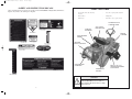
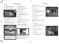
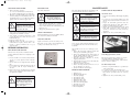
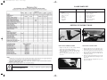
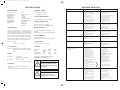
2303 Current Artwork 7-2003
18/5/06
2:11 PM
Page 1
Warranty Conditions
Owners Manual
AUSTRALIA & NEW ZEALAND ONLY
Rover Mowers Limited warrant that this machine is free from
defects in material and workmanship. This warranty is limited
to making good or replacing any part which appears upon
inspection by the manufacturer or his agent to be defective in
material or workmanship.
The engine used to power this machine is warranted by the
manufacturer whose warranty statement has been included
with the machine. As the warranty for the engine may differ
from the warranty for the other components, you are advised to
read the engine manufacturer’s warranty carefully
For other items this warranty shall apply for a period of 12
months from the date of purchase except for products used
commercially where the warranty is limited to 90 days.
This warranty does not obligate the manufacturer, his agents or
dealers to bear the transport costs incurred in the repair or
replacement of any defective part.
This warranty excludes fair wear and tear, or any damage
caused by misuse or abuse. Parts such as blades, blade bolts, vbelts and spark plugs, which can be subjected to use beyond
their normal intended working capacity are also excluded.
This warranty is void if parts other than genuine have been
used or if repairs or alterations have been made without the
manufacturer’s written authority.
The above warranty does not exclude any condition or
warranty implied by the Trade Practices Act 1974 or any other
relevant legislation which implies any condition which cannot
be excluded.
EXTENDED WARRANTY: For domestic use only, a 24
month extended warranty applies. It requires the customer to
complete the ‘2 year warranty registration card’, and forward
along with a copy of the cash register receipt to “Warranty,
Rover Mowers Limited”, Normal warranty exclusions as listed
still apply.
REMEMBER:
PROOFOFPURCHASE IS THE RESPONSIBILITYOFTHE OWNER AND
IS NECESSARY PRIOR TO WARRANTY WORK BEING UNDERTAKEN.
REPAIRS MUST BE CARRIED OUT BY AN AUTHORISED ROVER
DEALER /SERVICE AGENT AND GENUINE SPARE PARTS MUST BE
USED OR YOUR WARRANTY WILL BE VOID.
Online warranty registration - www.rovermowers.com.au
RANGER
TM
AUTO-DRIVE
Model No. 53179
For your record:
Dealer’s Name:..............................................................................................................
Dealer’s Address: ..........................................................................................................
Dealer’s Phone No: .......................................................................................................
Product Model No: ........................................................................................................
Product Serial No: .........................................................................................................
Date of Purchase: ..........................................................................................................
Rover Mowers Limited reserves the right to make changes of and add
improvements upon its product at any time without notice or
obligation. The Company also reserves the right to discontinue
manufacture of any product at its discretion at any time.
ISO 9001 Lic 10168
Standards Australia
A.B.N. 11 000 257 303
Rover Mowers Australia
PO Box 1235
Eagle Farm. Qld 4009
Australia.
RECYCLED PAPER
Rover Mowers New Zealand
East Tamaki,
Auckland.
New Zealand.
This Rover Owners Manual has been printed on 100% Australian
recycled paper as a sign of Rover Mowers’ commitment to Greening
Australia and New Zealand.
GWAIL GROUP
04012303 Rev. G
PRINTED IN AUSTRALIA
© Copyright 8/2005
TM
2303 Current Artwork 7-2003
18/5/06
2:11 PM
Page 3
SAFETY AND INSTRUCTION DECALS
Safety and Instruction decals that are mounted on the RANGER Rear Engine Ride On Mower.
Replace any that become damaged or illegible.
SAFETY FEATURES
-
Traction drive, blade drive and safety
interlock
-
Low centre of gravity, stable wide track
-
Enclosed drives
-
Parking brake
-
Full footrests
-
Convenient - easy to operate controls
AUTOMOTIVE TYPE
STEERING WHEEL
AUTO BELT
TENSIONER
ADJUSTABLE
MOULDED SEAT
GEARED
STEERING
REAR MOUNTED
ENGINE
LOW TONE
EXHAUST MUFFLER
REAR MOUNTED
NUDGE BAR
P/N A16374
BIG 76cm (30”) CUT
CONTOUR FOLLOWING
CUTTER HEAD
RUBBER SEAT
BUFFERS
WARNING
“If fitted with accessories, including any
authorised ROVER accessories such as a
Grass Catcher, this mower may not comply
with AS 3792.1.”
16
1
2303 Current Artwork 7-2003
18/5/06
2:11 PM
Page 4
SPECIFICATIONS
ROVER RANGER
TROUBLE SHOOTING
PROBLEM
STEERING WHEEL
Engine loses power.
Model No
Engine Make
Engine Model No.
Engine Power
Fuel Capacity
Oil Capacity
Spark Plug Type
Spark Plug Gap
Engine Oil
53179
Briggs & Stratton
215907
10.5 Hp.
2.27 Litres
1.4 Litres (no filter)
Champion RC12YC
0.7 to 0.8mm
Refer to
manufacturers
instructions
325 mm Dia. Steering Wheel.
1 - 1/4turns lock to lock.
CLUTCH/ BRAKE PEDAL
Foot operated pedal. Left side of machine.
Engine over heats.
Hand operated catch. Left hand side.
Used in conjunction with cluth/brake pedal.
TRANSMISSION
DRIVE SELECTOR
Auto-Drive system consists of a continuous belt being
driven by the engine pulley over two drive pulleys and
around a return pulley. Friction plates are brought into
contact with the drive pulleys to impart either forward
or reverse motion to the rear drive wheels by means of
a drive selector pedal on the right side of the machine.
Foot operated pedal located on right side of the
machine.
Spring loaded so as to return to neutral position.
Cutter does not rotate.
Lever right hand side.
8 height of cut positions from 15mm to 65mm.
Lever located left side of seat cowl.
Wheel Base
Track
TYRES
Turning Circle
Turning Radius
4.1 x 6 Tube
Pressure 140 Kpa maximum.
(20psi)
16 x 6.5 x 8 Tubeless
Pressure 96 Kpa maximum. (14psi)
1.35m
0.63m R
0.69m F
5.8m
2.0m
Length
Width
1.64m
0.80m
Height
Weight
0.95m
195kg
Engine does not start, hard
to start, loses power, or fails to
keep running.
1. Remove obstruction from
cooling fins and air passages.
1. Engine mounting bolts are loose.
2. Loose cutter pulley, idler pulley or
drive pulley.
3. Cutter assembly is unbalanced.
4. Cutter assembly is loose.
1. Tighten mounting bolts.
2. Tighten the appropriate pulley.
2. Adjust the carburettor.
3. Add oil to crankcase.
4. Select a lower speed to reduce load.
3. Replace broken blades in sets.
4. Tighten securing nut.
1. Cutter drive belt is worn, loose or
broken
2. Cutter drive belt is off pulley.
1. Install new cutter drive belt.
1. Drive belt is worn, loose or
broken
2. Drive belt is off pulley.
3. Unable to select forward
or reverse.
Install new drive belt.
1. Fuel tank is empty.
2. Speed selected.
3. Cutter Drive is engaged.
4. Spark plug is loose.
5. Spark plug lead is loose or
disconnected from spark plug.
6. Spark plug gap is incorrect.
1. Full fuel tank with petrol.
2. Select Neutral.
3. Disengage Cutter Drive.
4. Tighten spark plug.
5. Install spark plug lead on
spark plug.
6. Set spark gap between electrodes at
0.7mm to 0.8mm
7. Install new correctly gapped
spark plug.
8. Install correct spark plug.
9. Check electrical system to
ensure good contact.
10. Adjust the carburettor.
11. Clean the air cleaner element.
12. Inspect and open vent.
2. Install cutter drive belt.
2. Install drive belt.
3. Have machine serviced by
Authorised Service Dealer.
}
The safety of the user and others
involved. Personal injury may
result should this information be
disregarded.
Engine does not idle or idles poorly.
CAUTION
Follow these instructions
carefully to avoid mower
damage and loss of warranty.
1. Air cleaner is dirty.
2. Oil level in crankcase is low.
3. Cooling fins and air passages
under engine blower housing are
plugged.
4. Idle speed is too low or high.
5. Dirt or water is in fuel system.
6. Vent hole in fuel tank is plugged.
7. Spark plug is pitted fouled or
defective in some other way.
2
3. Select a lower speed to reduce load.
4. Clean air cleaner element.
5. Have machine serviced by
Authorised Service Dealer.
6. Adjust the carburettor.
7. Install new correctly gapped
Spark plug.
1. Cooling fins and air passages
under engine blower housing are
Blocked.
2. Carburettor is adjusted incorrectly.
3. Oil level in crankcase is low.
4. Engine load is excessive.
10. Carburettor is adjusted incorrectly.
11. Air cleaner is dirty.
12. Vent hole in fuel tank is plugged.
13. Dirt or water in fuel system
14. Dead battery.
15. Defective Electronic Ignition
System.
16. Defective Safety Switches.
WARNING
* Throttle control with Fast, Slow and Choke
positions.
* Key switch with OFF, ON and START positions.
1. Add oil to crankcase.
2. Remove obstruction from
passages.
7. Spark plug is pitted, fouled or
defective in some other way.
8. Wrong spark plug is used.
9. Electrical connections are loose.
To emphasise special information the words
WARNING and CAUTION are used.
CONTROLS
CORRECTIVE ACTION
\
GENERAL
Model 160 Full floating pressed steel housing with
right side discharge. Width of cut 760mm
(30”).
Rear Tyres-
Mower does not drive
CUTTER DRIVE
CUTTING HEAD
Front Tyres-
Mower vibrates abnormally
CUTTING HEIGHT
Max. Speed = 8.6km/hr
1. Oil level in crank case is low.
2. Cooling fins and air passages
under engine blower housing are
blocked.
3. Engine load is excessive.
4. Air cleaner is dirty.
5. Dirt or water is in fuel system.
6. Carburettor is adjusted incorrectly.
7. Spark plug is pitted, fouled or
defective in some other way.
PARKING BRAKE KNOB
Ground speed at 3600 rpm is variable due to the AutoDrive system depending on pressure applied to the
drive selector pedal.
POSSIBLE CAUSES
15
13. Have machine serviced by
Authorised Service Dealer.
1. Clean air cleaner element.
2. Add oil to crankcase.
3. Remove obstruction from cooling
fins and air passages.
4. Adjust the carburettor.
5. Have machine serviced by
Authorised Service Dealer.
6. Clean fuel tank vent.
7. Install new correctly gapped spark
plug.
2303 Current Artwork 7-2003
18/5/06
2:11 PM
Page 5
LOOSE PARTS KIT
DESCRIPTION
QTY
Steering wheel
Roll Pin
Stone guard assembly
Spring stone guard
“E” Clip
Ignition keys
Plug spanner
Pop Rivets
USE
1
1
1
1
1
2
1
2
On steering shaft
Secure steering wheel to shaft
Fitted to cutterhead
On stone guard pivot rod
In groove in pivot rod
To start machine
Plug removal and fitting
Seat safety switch
SETTING UP INSTRUCTIONS
Fig. 2
Fig. 4
INSTALLING STEERING WHEEL
INSTALLING STONE GUARD
1. Slip the steering wheel over the steering shaft and
align the wheel hole with the shaft hole.
2. Insert a drift punch – partially through the holes to
maintain alignment and insert the roll pin in the
opposite side. Fig. 2
3. Drive the roll pin in until flush with the outside of
the wheel.
1. Slip the spring into the stone guard pivot rod so
that the short leg rests on top of the stone guard.
2. Now twist the spring as shown and feed the end of
the pivot rod into the forward pivot bracket. Fig 3.
3. Insert the short end of the pivot rod fully into the
rearward pivot bracket.
4. Release the spring. It should spring down onto the
top of the cutterhead and be tensioning the stone
guard down.
5. Secure by clipping the “E” Clip into the groove on
the pivot rod. Fig. 4.
WARNING
Before undertaking any maintenance, cleaning or adjustments, apply the parking brake
and remove the ignition key.
14
Fig. 3
3
2303 Current Artwork 7-2003
18/5/06
2:11 PM
Page 6
INSTALLING THE BATTERY
FILL FUEL TANK
1. Remove the battery as follows
(a) remove the terminal cables from the battery.
(b) undo the wingnuts and remove the clamp bar.
2. The battery is not filled with Electrolyte. This should
be done by adding 33% strength battery acid to each
cell until the plates are covered. Electrolyte must be
purchased from a local battery supply outlet.
Refer Safety Instructions.
CAUTION
MAINTENANCE
CAUTION
WARNING
Use only unleaded petrol.
Do not mix oil with petrol
– engine damage may result.
The engine will stop if the
operator leaves the seat with the
speed selector engaged and/ or
the cutter drive engaged.
1. Clean around the fuel tank cap so foreign matter
cannot enter the tank when the cap is removed.
2. Using a funnel, fill the tank with unleaded petrol.
Replace the cap.
3. Wipe up any petrol that may have spilled.
Do not overfill battery, acid will
overflow into other parts of the
machine and severe corrosion and
deterioration will result.
3. Leave the filler caps off and connect the battery
charger to the battery terminals. Charge the battery at
4 Amps/Hour for a minimum of 6 hours.
4. After charging, check that the Electrolyte is still
covering the plates, if not, add to the correct level.
Install the filler caps.
5. Replace the battery and secure.
6. Install the positive (red) cable to the positive (+)
terminal and the negative (black) cable to the
negative (-) battery terminal. Secure for good
electrical contact.
SAFETY SWITCH ADJUSTMENTS
The engine will not start unless the clutch/brake pedal
is depressed and the cutter drive is disengaged.
Clutch Brake Pedal
1. Depress the clutch brake pedal and apply the parking
brake.
2. Loosen the two safety switch retaining screws and
slide the safety switch towards the rear of the mower.
Fig. 29
3. Depress the clutch brake pedal and release the
parking brake allowing the clutch brake pedal to
return to its normal disengaged position.
4. Slide the safety switch towards the tab on the clutch
brake shaft. Position the safety switch with a
clearance of 6mm between the safety switch body
and the tab.
5. Tighten the two safety switch retaining screws.
WARNING
If the interlock system fails, see
an authorised Rover Service
Dealer. Do not operate the mower
until the fault is corrected.
CHECK TYRE PRESSURE
CAUTION
Check and maintain tyre pressure at 140 KPA (20PSI)
front and 96 KPA (14PSI) rear maximum.
The safety switch circuit may
become defective if wet. Do not
spray switches and connections.
ADJUSTING THE SEAT
STORAGE:
Tip the seat forward, loosen the seat securing screws.
Relocate the seat for operator comfort. Tighten the seat
securing screws and lower the seat. Fig 5.
BEFORE OPERATING
FILL CRANK CASE WITH OIL
The rider mower may be delivered without oil in the
crankcase. Oil must be added before attempting to start
the engine.
1. Place the machine on level surface. Ensure that the
oil plug is securely tightened. Clean around the
dipstick.
2. Unscrew and remove the dipstick from the oil filler
tube.
3. Insert a funnel into the filler tube and slowly add oil
in accordance with the engine manufacturer’s
direction.
4. Ensure oil level is at the full mark on the dipstick
when screwed completely in. When finished, replace
the dipstick and re-tighten.
Fig. 5
Never store the engine with fuel in tank indoors or in
poor ventilated enclosures where the fuel fumes may
accumulate.
If the machine is to be stored over 30 days proceed as
follows:
1. Remove all fuel from the carburettor and the fuel
tank to prevent varnish-like gum deposits.
2. Remove the spark plug and pour 30ml of engine oil
into the cylinder. Crank the engine several times to
distribute the oil. Replace the spark plug.
3. Clean the engine and cooling fins, etc., and any
clippings, dirt and chaff.
4. Clean the underside of the mower and cutting unit.
Paint any chips or scratches.
5. Lubricate the chassis components.
6. Remove and charge the battery and store in a cool
dry spot. Recharge every 30 days.
7. Store the machine in a clean dry place.
Fig. 29 Clutch brake safe switch
Cutter Engagement Safety Switch
The cutter engagement safety switch does not require
any routine adjustment. It should be checked
occasionally for operation, working condition and it’s
fasteners checked for tightness.
Seat Panel Safety Switch
1. Raise the seat panel and allow it to open till it rests
on the steering wheel.
2. Loosen the two safety switch retaining screws.
3. Position the safety switch to give the safety switch
button 10mm of protrusion above the cowl body
panel.
4. Tighten the two safety switch retaining screws.
REMOVAL FROM STORAGE
1. Change the oil
2. Fill the fuel tank with fuel
3. Check the spark plug
4. Check the drive belts
5. Check the drive chain
6. Lubricate the drive chain
7. Lubricate the pivot points
8. Grease the front axle spindles
9. Check the tyre pressure
10.Check safety interlock
11.Check cutting blades.
CAUTION
Avoid premature engine failure by
ensuring the funnel is clean so
contaminants are not introduced
into the crankcase. Wipe any oil
spills so it will not cause dirt to
collect on the engine.
4
13
2303 Current Artwork 7-2003
18/5/06
2:11 PM
Page 7
MAINTENANCE
TO FIT NEW BELT
STEERING RODS
4. Ensure that the peg on rack assembly (A) engages in
the front slot of cam plate assembly. (B) Fig. 26
5. Fit new drive belt around pulleys.
6. Draw the spring plate back into position and secure.
Check that the spring finger (C) engages in the first
couple of teeth on the rack assembly. Fig. 26
Should not normally require resetting.
1. Loosen the rod lock nut (A). Fig. 11
2. Release the fixing bolt.
3. Turn the tie rod end to adjust for length.
Clockwise to shorten, anti-clockwise to lengthen.
4. Replace the fixing bolt and tighten.
5. Tighten the rod lock nut.
6. Make sure the rod is free to pivot.
CUTTER HEAD TILT
This will not normally require resetting.
1. Loosen the U-Bracket nuts (B) Fig. 12
2. Adjust the nuts up or down to set tilt.
3. Model 160 (760mm cut) requires the back of the
blade circle tilted 15mm above the front of the blade
circle in low cut position.
4. Re-tighten all nuts.
GREASE
If the spring finger engagement in the rack assembly is
not at the start of the rack assembly, proceed as follows:7. Release the spring plate as per step (2)
8. Loosen the four locknuts (A) on the engine hold
down bolts. Fig. 27
9. Loosen locknuts (B) on engine pulley guard and
slide to the rear. Fig. 27
10.Adjust nyloc nut (C) on motor adjustment plate to
move the engine to the rear and repeat step (6).
11.Re-tighten engine mounting bolts and re-position
belt guard with 2-3mm clearance between belt guard
and engine pulley.
Fig. 26
B
CONTROLS
1. THROTTLE CONTROL
1
2
Mounted on the control panel and connected to the
engine carburettor controls. Has the symbols for Slow,
Fast and Choke. Fig. 6
2. IGNITION SWITCH
This switch is part of the battery ignition system and has
three positions marked for Off, On and Start. The switch
is key operated and automatically returns to the On
position from the Start position when released. Fig. 6
3. BRAKE/ CLUTCH
Foot operated pedal on the left side of machine.
Depressing the pedal neutralises the drive belt and
engages the Brake Disc. Fig. 7
Fig. 6
STEERING STOPS
These will not normally require resetting.
1. Check if the steering segment gear rotates in both
directions.
2. Loosen the locknut on the front beam and adjust the
bolt till number of turns in both directions is equal.
3. Re-tighten the Locknut.
HEIGHT OF CUT ADJUSTMENT
To adjust the height of cut rotate the nyloc nut (A)
situated under the centre of machine on the rear
cutterhead support assembly. Adjust the nyloc nut to
obtain low cut at front of blade circle of 15mm. Fig. 28
A
Fig. 27
Hand operated knob left hand side. Depressing the
brake/clutch foot pedal enables this knob to be engaged
and disengaged. Brake is locked on with knob in up
position. Fig. 7
5. DRIVE SELECTION
5
Foot operated right hand side. Depress with toe pressure
gives forward motion, depress with heel gives reverse
motion. Automatically returns to neutral position when
foot is removed. Fig. 7
6. CUTTING HEIGHT ADJUSTER
3
Located on right side of seat. (Fig. 7) with low cut at
bottom and high cut at the top setting. Fig.7
4
7. CUTTER DRIVE
Fig. 28
NOTE:
After a period of time the drive belt will stretch
past the limit of the auto-tensioner. The autotensioner can be reset to allow for this stretching
by following the above instructions- steps (7) to
(11). Re-grease the bearing area under cam plate
when fitting new belt. Fig. 26
4. PARKING BRAKE
Lever located on left hand side of seat mounting box.
Down position disengages blade drive and applies blade 7
brake, up position engages blades. Fig. 7
Fig. 7
SAFETY INTERLOCK SYSTEM
The safety interlock system has been designed for your
protection and should not be tampered with. It gives
the Ranger the following characteristics.
12
5
6
2303 Current Artwork 7-2003
18/5/06
2:11 PM
Page 8
OPERATING INSTRUCTIONS
MAINTENANCE
AUTO - DRIVE OPERATION
Forward and reverse movement of the mower is controlled by the drive selector pedal. Ground speed of the ride-on
mower is controlled by the amount of pressure on the drive selector pedal. Ensure that the mower user is familiar
with this means of operation before operating the mower, particularly in tight confined areas.
AUTO-DRIVE
DRIVE SELECTOR PEDAL
The Auto-Drive friction plates and drive pulleys are
factory set for travel required along a keyed shaft and
this should not need adjusting.
The pedal angle can be tilted either forward or back to
suit individual requirements if necessary.
1. Loosen locknuts (A) on control rod. Fig. 24
2. Tilt control pedal to required angle to give maximum
operator comfort.
3. Re-tighten locknuts.
TO START ENGINE
NOTE:
WARNING
The engine will not start unless the cutter
drive is disengaged, and clutch/brake
pedal is depressed and parking brake
applied.
The parking brake should always
be applied before leaving the
machine. The parking brake
must be released before
attempting to drive. Depress the
clutch/brake when starting or
coming to a rest. Do not use
sudden directional reversal which
can cause wheel spinning.
1. Depress clutch/brake pedal – Apply the parking
brake.
2. Move the drive selector to neutral.
3. Disengage the cutter drive.
4. Move the throttle lever to the choke position.
5. Turn the ignition key to the start position and release
when the engine starts.
6. Move the throttle lever to about 1/4 position.
Depress clutch/brake pedal.
Disengage the parking brake.
Select height of cut.
Move throttle to about 3/4 position.
Engage cutter drive.
Select desired drive.
Slowly release clutch/brake pedal and move off.
Depress clutch/brake pedal.
Shift the drive selector to neutral.
Disengage the cutter drive.
Apply the parking brake.
Move throttle lever to the fast position.
Turn the ignition key to Off. Remove the keys.
CAUTION
Do not over-tension belts or
drive chains.
AUTO BELT TENSIONER
REMEMBER
Fig. 22
1. Always look behind the machine before reversing.
2. Do not refuel when the engine is running or while the
engine is hot.
3. Keep bystanders away – Keep hands and feet clear of
moving parts.
4. Keep the machine clean of grass and debris.
5. Keep all safety devices (guards and switches) in
place and working.
DRIVE CHAIN ADJUSTMENT
TO STOP IN AN EMERGENCY
1. Depress brake/clutch pedal and drive selector pedal
together. (This disengages power from the engine
and engages the disc brake.)
2. Apply park brake and lock.
3. Move throttle to fast position and switch off ignition
key.
4. Dismount from the mower if it is safe to do so.
The continuous drive belt is kept under constant
tension by the Auto-Belt tensioner. This is set up
initially at the factory and should not need attention
unless the drive belt has stretched past its serviceable
use, indicated when the spring finger is engaged in red
area on the rack assembly.
Primary
1. Loosen off bolt ‘A’ Fig. 23
2. Slide idler back till chain tightens.
3. Re-tighten bolt ‘A’ and check chain for tight spots.
TO REMOVE OLD BELT
1. Loosen the two nuts (A) securing the spring plate.
Fig. 25
2. Remove the top bolt (B) from the spring plate while
holding the spring plate and slowly release the
tension on the spring and disengage the spring finger
from rack assembly by pressing outwards. Fig. 25
3. Remove old belt from around pulleys and discard.
Secondary
1. Loosen off bolt ‘B’ Fig. 23
2. Slide sprocket back till chain tightens.
3. Re-tighten bolt ‘B’ and check chain for tight spots.
CAUTION
6. Dirt or abrasives entering the engine via the air
cleaner due to –
(a) The air cleaner element not being serviced
regularly, or
(b) The air cleaner damaged or dislodged.
To avoid loss of control always
come to a complete stop before
changing drive direction and
slow down before turning.
B
Fig. 23
6
SPRING FINGER
SPRING PLATE
A check after the first two hours
of operation is recommended.
Engine failure or rapid engine
wear mainly results from the
following causes –
WARNING
A
Fig. 24
When engaging the cutter drive lever or releasing the
clutch/brake pedal, always operate slowly. Do not use a
jerking motion. Moving these controls too fast could
possibly overload and stall the engine.
TO STOP ENGINE
1.
2.
3.
4.
5.
6.
1. Loosen Locknut (A) Fig. 22
2. Centralise engagement lever with the friction plates
between the drive pulleys.
3. Re-tighten locknut (A). Fig. 22
ENGAGE CLUTCHES
TO MOW OR DRIVE
1.
2.
3.
4.
5.
6.
7.
If during operation it is found that the relationship
between forward and reverse has become unbalanced
adjust as follow:-
Fig. 25
11
A
2303 Current Artwork 7-2003
18/5/06
2:11 PM
Page 9
MAINTENANCE
PARKING BRAKE
CUTTERHEAD BRAKE
Should be regularly checked for operation.
Should always be checked for operation after
clutch/brake rods have been adjusted.
PAD REPLACEMENT
(Refer figure 19)
1. Remove the ‘R’ Clip (A) from
the push rod clevis pin and
remove the clevis pin and push
rod from brake arm assembly.
2. Remove the brake plate pivot
bolt (B), two spacers and
nyloc nut and remove the
Fig. 19
brake plate assembly.
3. Drill out the two retaining rivets which hold the Brake pad
assembly to the brake plate and discard the old brake pad and
backing plate. The replacement brake pads are fitted with a
chemically bonded backing plate, locate this backing plate
against the brake plate and retain with two 3/16” rivets. Part No:
A2901195.
4. Replace the brake plate to the cutterhead and adjust the cutterhead
brake.
CUTTER DRIVE ADJUSTMENT
1. Move cutter Height Selector Lever to No. 4
Position in Rack.
2. Move cutter Drive Lever to the Engaged position.
3. Adjust Push Rods Fig. 16 to give a spring
compression of 35mm. Fig. 17
CUTTERHEAD BRAKE ADJUSTMENT
1. With the cutterhead disengaged and in low cut
position.
2. Adjust the nyloc nut on the rod as per step 6 for
Cutter Drive Adjustment.
3. Adjust the tension on the spring using the lock nuts
to give length of 58mm. Fig. 20
Fig. 16
Fig. 20
STEERING GEARS
Fig. 17
AIR CLEANER
7. Dirt or abrasives entering the engine via the oil filler
tube due to-
Refer to engine manufacturer’s manual for detailed
instructions.
(a) Using a funnel not cleaned of dirt or grit, or,
(b) Topping up with contaminated oil stored in an
unclean container.
1. Pull up on air cleaner cover handle and rotate
towards engine.
2. Remove air cleaner cover.
3. Carefully lift air cleaner cartridge and pre-cleaner
from blower housing.
8. Lack of oil. It is important to(a) Check the oil level regularly (Every 5 hours of
operation)
(b) Maintain a full sump.
Note: To clean pre-cleaner, wash in soapy water.
Squeeze dry in a clean cloth. DO NOT OIL.
Periodically check the machine and the cutting
mechanism. If parts are worn or need replacing do so by
using only Genuine Rover Replacement parts.
4. Tap the air cleaner on a flat surface to dislodge any
loose debris. If contaminated, replace.
5. Clean the base of the air cleaner cartridge area
carefully to prevent any debris from entering engine.
6. Place the air cleaner pre-cleaner and cartridge into
the blower housing. The cartridge must fit securely
in base.
7. Align the tabs on the cover with the slots in the
blower housing and replace the cover.
8. Hook the handle and close the cover.
Before working on the mower, disconnect the spark plug
lead from the spark plug and place it where it cannot
contact the spark plug.
Check your Rover Ranger frequently for loose nuts,
bolts, belts, etc., and keep these items correctly
tightened and adjusted.
CAUTION
Petroleum solvents, such as
kerosene, are not to be used to
clean cartridge. They may cause
deterioration of the cartridge.
DO NOT OIL CARTRIDGE.
DO NOT USE PRESSURIZED
AIR TO CLEAN OR DRY
CARTRIDGE.
4. Adjust Locknut ‘A’ to give 7mm clearance to back of
Swivel Block. Fig 17
5. Disengage the Cutter Drive Selector Lever.
6. Adjust locknut ‘A’ in Fig. 20 to give Cutter
Engagement Lever a free travel of 30mm, from
bottom of slot in Fig. 18
NOTE:
Check to ensure lever has 30mm of free travel
by working lever.
Fig. 21
To adjust the excessive play caused by wear in the
gears.
1. Loosen the bolts securing steering shaft pivot block
(A)
2. Lightly tap the pivot block towards the layshaft pivot
and retighten bolts (A)
3. Check the steering gear engagement.
4. Check that there is no tight spots when turning the
steering wheel from lock to lock.
Fig. 18
10
7
2303 Current Artwork 7-2003
18/5/06
2:11 PM
Page 10
MAINTENANCE
MAINTENANCE
THROTTLE CONTROL
OIL CHANGE
Proper choke operation is dependant on the
adjustment of remote controls –
Refer engine manufacturers’ instructions.
1. Place the machine on a level surface. Start and run
the engine for a period to warm the oil.
1. Loosen the outer cable clamp screw on engine.
2. Set the throttle control to choke position.
3. Adjust the outer cable under clamp plate so that
choke is operated.
4. Tighten the clamp plate screw and check
(a) Choke does not operate in fast position,
(b) Stop switch operates correctly.
CARBURETTOR ADJUSTMENT
The carburettor has been factory set and should only
require occasional fine tuning.
Refer to Engine Manufacturer’s Owner’s Manual for
details adjustment procedures.
Fig. 8
2. Fit the drain tube to the drain fitting. Fig. 8
3. Place an oil pan under the end of drain tube.
4. Open the drain fitting about 1 turn and allow the oil
to drain completely.
5. Retighten the drain fitting and refill the sump with
new oil. For correct viscosity and service
classification, refer to the engine manufacturers’
instructions.
WHEEL REMOVAL
Remove spark plug lead and disengage cutter drive
before working on cutter unit, to prevent accidental
starting of the engine.
Before using the machine always inspect cutting unit to
ensure that the cutting disc, blades and blade fittings are
not worn or damaged.
Always check after striking a solid object. Do not
operate machine when unusual vibration occurs.
Replace worn or damaged blades in sets to preserve
balance.
Remove any build-up of grass or clogging within the
cutting unit, discharge chute or stone guard.
Fig. 13
Always deflate tyre before moving
rim nuts on front wheel only.
CUTTERHEAD REMOVAL
Front –
1. Chock the rear wheels and remove the front axle nut.
Fig. 13
2. Raise the front of the machine.
3. Slide the wheel from the shaft.
4. Replace in reverse order.
5. Re-tighten the axle nut firmly.
Rear –
1. Chock the front wheels and raise the rear of the
machine.
2. Remove the four wheel nuts.
3. Slide the wheel from the hub. Fig. 14
4. Refit the wheel to hub.
5. Replace the wheel nuts and tighten.
Never tamper with the engine
governor setting. Changing of
engine governor speed will
void engine warranty.
Fig. 12
The spark plug gap gradually increases during engine
running and should be checked periodically and
whenever the engine malfunctions.
1. Clean around the spark plug area so that dirt will not
enter the engine when the spark plug is removed.
2. Disconnect the spark plug lead and remove the spark
plug.
3. Check the condition of electrodes and ensure there is
no damage to insulator.
4. Carefully clean the spark plug. Do not grit blast.
5. Set the gap between 0.7mm to 0.8mm.
6. Install the spark plug in the engine and tighten.
Fig. 11
LUBRICATION GENERAL
Using General Purpose Grease – (Every 25 hours)
Grease nipples on front wheel pivots. Fig. 11
Cam plate bearing area. Fig. 26
Front Axle beam guides.
Grease nipples on steering pivot blocks. Fig. 21
Steering gears. Fig. 21
Grease nipples on engagement lever pivot.
Steeing pivot blocks. Fig. 23
Using Clean Engine Oil –
Jockey pivot arms
Throttle control cable.
Drive Chain. Fig. 23
Cutter drive lever pivot.
Clutch/Brake pedal pivot. Fig. 15
Tie rod ball ends. Fig. 11
All connecting rod pivots points.
COOLING SYSTEM
The Ranger has an air cooled 4 stroke engine. It must
be cleared frequently. Remove any build up of grass,
dirt or other debris from the
Cylinder
Cylinder head cooling fins
Cooling air intake screen
Carburettor governor levers and linkages.
NOTE:
All ball bearings are sealed and require no
maintenance.
This will ensure adequate cooling and correct engine
speed.
8
Fig. 14
WARNING
CAUTION
SPARK PLUG
1.
2.
3.
4.
CUTTING UNIT
1. Disconnect push rods & brake rod. Fig. 12
2. Remove the tensioning spring. A loop has been
provided on the spring to assist in this operation. Fig.
12
3. Slide cutterback towards back of machine and
remove belt from around cutterdeck pulley.
4. Undo large retaining washer bolts (A) Fig. 12 This
will allow front of deck to be lowered to ground.
5. Slide cutterdeck forward. This will allow the rear to
be lowered to the ground and be slid from under the
machine.
6. Replace in reverse order.
BRAKE CALIPER ADJUSTMENT
Fig. 15
1. Loosen locknut ‘A’ Fig. 15
2. Adjust Bolt ‘B’ till brake calliper ‘C’ touches brake
Disc.
3. Re-tighten locknut ‘A’.
NOTE:
To remove cutterdeck belt from machine, the
belt guard has to be moved away from the
drive pulley to allow the belt to be removed
from the V-groove and the cutterhead lifting
rod is to be disengaged from the cutterhead
selection arm assembly to allow belt to be
drawn out.
BRAKE ARM ADJUSTMENT
1. Check that brake calliper is correctly adjusted.
2. Adjust locknut ‘E’ Fig. 15. Till brake arm ‘D’ Pad
comes into contact with disc.
3. Check operation of brake to ensure park brake can be
applied, and brake operates correctly.
9
2303 Current Artwork 7-2003
18/5/06
2:11 PM
Page 9
MAINTENANCE
PARKING BRAKE
CUTTERHEAD BRAKE
Should be regularly checked for operation.
Should always be checked for operation after
clutch/brake rods have been adjusted.
PAD REPLACEMENT
(Refer figure 19)
1. Remove the ‘R’ Clip (A) from
the push rod clevis pin and
remove the clevis pin and push
rod from brake arm assembly.
2. Remove the brake plate pivot
bolt (B), two spacers and
nyloc nut and remove the
Fig. 19
brake plate assembly.
3. Drill out the two retaining rivets which hold the Brake pad
assembly to the brake plate and discard the old brake pad and
backing plate. The replacement brake pads are fitted with a
chemically bonded backing plate, locate this backing plate
against the brake plate and retain with two 3/16” rivets. Part No:
A2901195.
4. Replace the brake plate to the cutterhead and adjust the cutterhead
brake.
CUTTER DRIVE ADJUSTMENT
1. Move cutter Height Selector Lever to No. 4
Position in Rack.
2. Move cutter Drive Lever to the Engaged position.
3. Adjust Push Rods Fig. 16 to give a spring
compression of 35mm. Fig. 17
CUTTERHEAD BRAKE ADJUSTMENT
1. With the cutterhead disengaged and in low cut
position.
2. Adjust the nyloc nut on the rod as per step 6 for
Cutter Drive Adjustment.
3. Adjust the tension on the spring using the lock nuts
to give length of 58mm. Fig. 20
Fig. 16
Fig. 20
STEERING GEARS
Fig. 17
AIR CLEANER
7. Dirt or abrasives entering the engine via the oil filler
tube due to-
Refer to engine manufacturer’s manual for detailed
instructions.
(a) Using a funnel not cleaned of dirt or grit, or,
(b) Topping up with contaminated oil stored in an
unclean container.
1. Pull up on air cleaner cover handle and rotate
towards engine.
2. Remove air cleaner cover.
3. Carefully lift air cleaner cartridge and pre-cleaner
from blower housing.
8. Lack of oil. It is important to(a) Check the oil level regularly (Every 5 hours of
operation)
(b) Maintain a full sump.
Note: To clean pre-cleaner, wash in soapy water.
Squeeze dry in a clean cloth. DO NOT OIL.
Periodically check the machine and the cutting
mechanism. If parts are worn or need replacing do so by
using only Genuine Rover Replacement parts.
4. Tap the air cleaner on a flat surface to dislodge any
loose debris. If contaminated, replace.
5. Clean the base of the air cleaner cartridge area
carefully to prevent any debris from entering engine.
6. Place the air cleaner pre-cleaner and cartridge into
the blower housing. The cartridge must fit securely
in base.
7. Align the tabs on the cover with the slots in the
blower housing and replace the cover.
8. Hook the handle and close the cover.
Before working on the mower, disconnect the spark plug
lead from the spark plug and place it where it cannot
contact the spark plug.
Check your Rover Ranger frequently for loose nuts,
bolts, belts, etc., and keep these items correctly
tightened and adjusted.
CAUTION
Petroleum solvents, such as
kerosene, are not to be used to
clean cartridge. They may cause
deterioration of the cartridge.
DO NOT OIL CARTRIDGE.
DO NOT USE PRESSURIZED
AIR TO CLEAN OR DRY
CARTRIDGE.
4. Adjust Locknut ‘A’ to give 7mm clearance to back of
Swivel Block. Fig 17
5. Disengage the Cutter Drive Selector Lever.
6. Adjust locknut ‘A’ in Fig. 20 to give Cutter
Engagement Lever a free travel of 30mm, from
bottom of slot in Fig. 18
NOTE:
Check to ensure lever has 30mm of free travel
by working lever.
Fig. 21
To adjust the excessive play caused by wear in the
gears.
1. Loosen the bolts securing steering shaft pivot block
(A)
2. Lightly tap the pivot block towards the layshaft pivot
and retighten bolts (A)
3. Check the steering gear engagement.
4. Check that there is no tight spots when turning the
steering wheel from lock to lock.
Fig. 18
10
7
2303 Current Artwork 7-2003
18/5/06
2:11 PM
Page 8
OPERATING INSTRUCTIONS
MAINTENANCE
AUTO - DRIVE OPERATION
Forward and reverse movement of the mower is controlled by the drive selector pedal. Ground speed of the ride-on
mower is controlled by the amount of pressure on the drive selector pedal. Ensure that the mower user is familiar
with this means of operation before operating the mower, particularly in tight confined areas.
AUTO-DRIVE
DRIVE SELECTOR PEDAL
The Auto-Drive friction plates and drive pulleys are
factory set for travel required along a keyed shaft and
this should not need adjusting.
The pedal angle can be tilted either forward or back to
suit individual requirements if necessary.
1. Loosen locknuts (A) on control rod. Fig. 24
2. Tilt control pedal to required angle to give maximum
operator comfort.
3. Re-tighten locknuts.
TO START ENGINE
NOTE:
WARNING
The engine will not start unless the cutter
drive is disengaged, and clutch/brake
pedal is depressed and parking brake
applied.
The parking brake should always
be applied before leaving the
machine. The parking brake
must be released before
attempting to drive. Depress the
clutch/brake when starting or
coming to a rest. Do not use
sudden directional reversal which
can cause wheel spinning.
1. Depress clutch/brake pedal – Apply the parking
brake.
2. Move the drive selector to neutral.
3. Disengage the cutter drive.
4. Move the throttle lever to the choke position.
5. Turn the ignition key to the start position and release
when the engine starts.
6. Move the throttle lever to about 1/4 position.
Depress clutch/brake pedal.
Disengage the parking brake.
Select height of cut.
Move throttle to about 3/4 position.
Engage cutter drive.
Select desired drive.
Slowly release clutch/brake pedal and move off.
Depress clutch/brake pedal.
Shift the drive selector to neutral.
Disengage the cutter drive.
Apply the parking brake.
Move throttle lever to the fast position.
Turn the ignition key to Off. Remove the keys.
CAUTION
Do not over-tension belts or
drive chains.
AUTO BELT TENSIONER
REMEMBER
Fig. 22
1. Always look behind the machine before reversing.
2. Do not refuel when the engine is running or while the
engine is hot.
3. Keep bystanders away – Keep hands and feet clear of
moving parts.
4. Keep the machine clean of grass and debris.
5. Keep all safety devices (guards and switches) in
place and working.
DRIVE CHAIN ADJUSTMENT
TO STOP IN AN EMERGENCY
1. Depress brake/clutch pedal and drive selector pedal
together. (This disengages power from the engine
and engages the disc brake.)
2. Apply park brake and lock.
3. Move throttle to fast position and switch off ignition
key.
4. Dismount from the mower if it is safe to do so.
The continuous drive belt is kept under constant
tension by the Auto-Belt tensioner. This is set up
initially at the factory and should not need attention
unless the drive belt has stretched past its serviceable
use, indicated when the spring finger is engaged in red
area on the rack assembly.
Primary
1. Loosen off bolt ‘A’ Fig. 23
2. Slide idler back till chain tightens.
3. Re-tighten bolt ‘A’ and check chain for tight spots.
TO REMOVE OLD BELT
1. Loosen the two nuts (A) securing the spring plate.
Fig. 25
2. Remove the top bolt (B) from the spring plate while
holding the spring plate and slowly release the
tension on the spring and disengage the spring finger
from rack assembly by pressing outwards. Fig. 25
3. Remove old belt from around pulleys and discard.
Secondary
1. Loosen off bolt ‘B’ Fig. 23
2. Slide sprocket back till chain tightens.
3. Re-tighten bolt ‘B’ and check chain for tight spots.
CAUTION
6. Dirt or abrasives entering the engine via the air
cleaner due to –
(a) The air cleaner element not being serviced
regularly, or
(b) The air cleaner damaged or dislodged.
To avoid loss of control always
come to a complete stop before
changing drive direction and
slow down before turning.
B
Fig. 23
6
SPRING FINGER
SPRING PLATE
A check after the first two hours
of operation is recommended.
Engine failure or rapid engine
wear mainly results from the
following causes –
WARNING
A
Fig. 24
When engaging the cutter drive lever or releasing the
clutch/brake pedal, always operate slowly. Do not use a
jerking motion. Moving these controls too fast could
possibly overload and stall the engine.
TO STOP ENGINE
1.
2.
3.
4.
5.
6.
1. Loosen Locknut (A) Fig. 22
2. Centralise engagement lever with the friction plates
between the drive pulleys.
3. Re-tighten locknut (A). Fig. 22
ENGAGE CLUTCHES
TO MOW OR DRIVE
1.
2.
3.
4.
5.
6.
7.
If during operation it is found that the relationship
between forward and reverse has become unbalanced
adjust as follow:-
Fig. 25
11
A
2303 Current Artwork 7-2003
18/5/06
2:11 PM
Page 7
MAINTENANCE
TO FIT NEW BELT
STEERING RODS
4. Ensure that the peg on rack assembly (A) engages in
the front slot of cam plate assembly. (B) Fig. 26
5. Fit new drive belt around pulleys.
6. Draw the spring plate back into position and secure.
Check that the spring finger (C) engages in the first
couple of teeth on the rack assembly. Fig. 26
Should not normally require resetting.
1. Loosen the rod lock nut (A). Fig. 11
2. Release the fixing bolt.
3. Turn the tie rod end to adjust for length.
Clockwise to shorten, anti-clockwise to lengthen.
4. Replace the fixing bolt and tighten.
5. Tighten the rod lock nut.
6. Make sure the rod is free to pivot.
CUTTER HEAD TILT
This will not normally require resetting.
1. Loosen the U-Bracket nuts (B) Fig. 12
2. Adjust the nuts up or down to set tilt.
3. Model 160 (760mm cut) requires the back of the
blade circle tilted 15mm above the front of the blade
circle in low cut position.
4. Re-tighten all nuts.
GREASE
If the spring finger engagement in the rack assembly is
not at the start of the rack assembly, proceed as follows:7. Release the spring plate as per step (2)
8. Loosen the four locknuts (A) on the engine hold
down bolts. Fig. 27
9. Loosen locknuts (B) on engine pulley guard and
slide to the rear. Fig. 27
10.Adjust nyloc nut (C) on motor adjustment plate to
move the engine to the rear and repeat step (6).
11.Re-tighten engine mounting bolts and re-position
belt guard with 2-3mm clearance between belt guard
and engine pulley.
Fig. 26
B
CONTROLS
1. THROTTLE CONTROL
1
2
Mounted on the control panel and connected to the
engine carburettor controls. Has the symbols for Slow,
Fast and Choke. Fig. 6
2. IGNITION SWITCH
This switch is part of the battery ignition system and has
three positions marked for Off, On and Start. The switch
is key operated and automatically returns to the On
position from the Start position when released. Fig. 6
3. BRAKE/ CLUTCH
Foot operated pedal on the left side of machine.
Depressing the pedal neutralises the drive belt and
engages the Brake Disc. Fig. 7
Fig. 6
STEERING STOPS
These will not normally require resetting.
1. Check if the steering segment gear rotates in both
directions.
2. Loosen the locknut on the front beam and adjust the
bolt till number of turns in both directions is equal.
3. Re-tighten the Locknut.
HEIGHT OF CUT ADJUSTMENT
To adjust the height of cut rotate the nyloc nut (A)
situated under the centre of machine on the rear
cutterhead support assembly. Adjust the nyloc nut to
obtain low cut at front of blade circle of 15mm. Fig. 28
A
Fig. 27
Hand operated knob left hand side. Depressing the
brake/clutch foot pedal enables this knob to be engaged
and disengaged. Brake is locked on with knob in up
position. Fig. 7
5. DRIVE SELECTION
5
Foot operated right hand side. Depress with toe pressure
gives forward motion, depress with heel gives reverse
motion. Automatically returns to neutral position when
foot is removed. Fig. 7
6. CUTTING HEIGHT ADJUSTER
3
Located on right side of seat. (Fig. 7) with low cut at
bottom and high cut at the top setting. Fig.7
4
7. CUTTER DRIVE
Fig. 28
NOTE:
After a period of time the drive belt will stretch
past the limit of the auto-tensioner. The autotensioner can be reset to allow for this stretching
by following the above instructions- steps (7) to
(11). Re-grease the bearing area under cam plate
when fitting new belt. Fig. 26
4. PARKING BRAKE
Lever located on left hand side of seat mounting box.
Down position disengages blade drive and applies blade 7
brake, up position engages blades. Fig. 7
Fig. 7
SAFETY INTERLOCK SYSTEM
The safety interlock system has been designed for your
protection and should not be tampered with. It gives
the Ranger the following characteristics.
12
5
6
2303 Current Artwork 7-2003
18/5/06
2:11 PM
Page 6
INSTALLING THE BATTERY
FILL FUEL TANK
1. Remove the battery as follows
(a) remove the terminal cables from the battery.
(b) undo the wingnuts and remove the clamp bar.
2. The battery is not filled with Electrolyte. This should
be done by adding 33% strength battery acid to each
cell until the plates are covered. Electrolyte must be
purchased from a local battery supply outlet.
Refer Safety Instructions.
CAUTION
MAINTENANCE
CAUTION
WARNING
Use only unleaded petrol.
Do not mix oil with petrol
– engine damage may result.
The engine will stop if the
operator leaves the seat with the
speed selector engaged and/ or
the cutter drive engaged.
1. Clean around the fuel tank cap so foreign matter
cannot enter the tank when the cap is removed.
2. Using a funnel, fill the tank with unleaded petrol.
Replace the cap.
3. Wipe up any petrol that may have spilled.
Do not overfill battery, acid will
overflow into other parts of the
machine and severe corrosion and
deterioration will result.
3. Leave the filler caps off and connect the battery
charger to the battery terminals. Charge the battery at
4 Amps/Hour for a minimum of 6 hours.
4. After charging, check that the Electrolyte is still
covering the plates, if not, add to the correct level.
Install the filler caps.
5. Replace the battery and secure.
6. Install the positive (red) cable to the positive (+)
terminal and the negative (black) cable to the
negative (-) battery terminal. Secure for good
electrical contact.
SAFETY SWITCH ADJUSTMENTS
The engine will not start unless the clutch/brake pedal
is depressed and the cutter drive is disengaged.
Clutch Brake Pedal
1. Depress the clutch brake pedal and apply the parking
brake.
2. Loosen the two safety switch retaining screws and
slide the safety switch towards the rear of the mower.
Fig. 29
3. Depress the clutch brake pedal and release the
parking brake allowing the clutch brake pedal to
return to its normal disengaged position.
4. Slide the safety switch towards the tab on the clutch
brake shaft. Position the safety switch with a
clearance of 6mm between the safety switch body
and the tab.
5. Tighten the two safety switch retaining screws.
WARNING
If the interlock system fails, see
an authorised Rover Service
Dealer. Do not operate the mower
until the fault is corrected.
CHECK TYRE PRESSURE
CAUTION
Check and maintain tyre pressure at 140 KPA (20PSI)
front and 96 KPA (14PSI) rear maximum.
The safety switch circuit may
become defective if wet. Do not
spray switches and connections.
ADJUSTING THE SEAT
STORAGE:
Tip the seat forward, loosen the seat securing screws.
Relocate the seat for operator comfort. Tighten the seat
securing screws and lower the seat. Fig 5.
BEFORE OPERATING
FILL CRANK CASE WITH OIL
The rider mower may be delivered without oil in the
crankcase. Oil must be added before attempting to start
the engine.
1. Place the machine on level surface. Ensure that the
oil plug is securely tightened. Clean around the
dipstick.
2. Unscrew and remove the dipstick from the oil filler
tube.
3. Insert a funnel into the filler tube and slowly add oil
in accordance with the engine manufacturer’s
direction.
4. Ensure oil level is at the full mark on the dipstick
when screwed completely in. When finished, replace
the dipstick and re-tighten.
Fig. 5
Never store the engine with fuel in tank indoors or in
poor ventilated enclosures where the fuel fumes may
accumulate.
If the machine is to be stored over 30 days proceed as
follows:
1. Remove all fuel from the carburettor and the fuel
tank to prevent varnish-like gum deposits.
2. Remove the spark plug and pour 30ml of engine oil
into the cylinder. Crank the engine several times to
distribute the oil. Replace the spark plug.
3. Clean the engine and cooling fins, etc., and any
clippings, dirt and chaff.
4. Clean the underside of the mower and cutting unit.
Paint any chips or scratches.
5. Lubricate the chassis components.
6. Remove and charge the battery and store in a cool
dry spot. Recharge every 30 days.
7. Store the machine in a clean dry place.
Fig. 29 Clutch brake safe switch
Cutter Engagement Safety Switch
The cutter engagement safety switch does not require
any routine adjustment. It should be checked
occasionally for operation, working condition and it’s
fasteners checked for tightness.
Seat Panel Safety Switch
1. Raise the seat panel and allow it to open till it rests
on the steering wheel.
2. Loosen the two safety switch retaining screws.
3. Position the safety switch to give the safety switch
button 10mm of protrusion above the cowl body
panel.
4. Tighten the two safety switch retaining screws.
REMOVAL FROM STORAGE
1. Change the oil
2. Fill the fuel tank with fuel
3. Check the spark plug
4. Check the drive belts
5. Check the drive chain
6. Lubricate the drive chain
7. Lubricate the pivot points
8. Grease the front axle spindles
9. Check the tyre pressure
10.Check safety interlock
11.Check cutting blades.
CAUTION
Avoid premature engine failure by
ensuring the funnel is clean so
contaminants are not introduced
into the crankcase. Wipe any oil
spills so it will not cause dirt to
collect on the engine.
4
13
2303 Current Artwork 7-2003
18/5/06
2:11 PM
Page 5
LOOSE PARTS KIT
DESCRIPTION
QTY
Steering wheel
Roll Pin
Stone guard assembly
Spring stone guard
“E” Clip
Ignition keys
Plug spanner
Pop Rivets
USE
1
1
1
1
1
2
1
2
On steering shaft
Secure steering wheel to shaft
Fitted to cutterhead
On stone guard pivot rod
In groove in pivot rod
To start machine
Plug removal and fitting
Seat safety switch
SETTING UP INSTRUCTIONS
Fig. 2
Fig. 4
INSTALLING STEERING WHEEL
INSTALLING STONE GUARD
1. Slip the steering wheel over the steering shaft and
align the wheel hole with the shaft hole.
2. Insert a drift punch – partially through the holes to
maintain alignment and insert the roll pin in the
opposite side. Fig. 2
3. Drive the roll pin in until flush with the outside of
the wheel.
1. Slip the spring into the stone guard pivot rod so
that the short leg rests on top of the stone guard.
2. Now twist the spring as shown and feed the end of
the pivot rod into the forward pivot bracket. Fig 3.
3. Insert the short end of the pivot rod fully into the
rearward pivot bracket.
4. Release the spring. It should spring down onto the
top of the cutterhead and be tensioning the stone
guard down.
5. Secure by clipping the “E” Clip into the groove on
the pivot rod. Fig. 4.
WARNING
Before undertaking any maintenance, cleaning or adjustments, apply the parking brake
and remove the ignition key.
14
Fig. 3
3
2303 Current Artwork 7-2003
18/5/06
2:11 PM
Page 4
SPECIFICATIONS
ROVER RANGER
TROUBLE SHOOTING
PROBLEM
STEERING WHEEL
Engine loses power.
Model No
Engine Make
Engine Model No.
Engine Power
Fuel Capacity
Oil Capacity
Spark Plug Type
Spark Plug Gap
Engine Oil
53179
Briggs & Stratton
215907
10.5 Hp.
2.27 Litres
1.4 Litres (no filter)
Champion RC12YC
0.7 to 0.8mm
Refer to
manufacturers
instructions
325 mm Dia. Steering Wheel.
1 - 1/4turns lock to lock.
CLUTCH/ BRAKE PEDAL
Foot operated pedal. Left side of machine.
Engine over heats.
Hand operated catch. Left hand side.
Used in conjunction with cluth/brake pedal.
TRANSMISSION
DRIVE SELECTOR
Auto-Drive system consists of a continuous belt being
driven by the engine pulley over two drive pulleys and
around a return pulley. Friction plates are brought into
contact with the drive pulleys to impart either forward
or reverse motion to the rear drive wheels by means of
a drive selector pedal on the right side of the machine.
Foot operated pedal located on right side of the
machine.
Spring loaded so as to return to neutral position.
Cutter does not rotate.
Lever right hand side.
8 height of cut positions from 15mm to 65mm.
Lever located left side of seat cowl.
Wheel Base
Track
TYRES
Turning Circle
Turning Radius
4.1 x 6 Tube
Pressure 140 Kpa maximum.
(20psi)
16 x 6.5 x 8 Tubeless
Pressure 96 Kpa maximum. (14psi)
1.35m
0.63m R
0.69m F
5.8m
2.0m
Length
Width
1.64m
0.80m
Height
Weight
0.95m
195kg
Engine does not start, hard
to start, loses power, or fails to
keep running.
1. Remove obstruction from
cooling fins and air passages.
1. Engine mounting bolts are loose.
2. Loose cutter pulley, idler pulley or
drive pulley.
3. Cutter assembly is unbalanced.
4. Cutter assembly is loose.
1. Tighten mounting bolts.
2. Tighten the appropriate pulley.
2. Adjust the carburettor.
3. Add oil to crankcase.
4. Select a lower speed to reduce load.
3. Replace broken blades in sets.
4. Tighten securing nut.
1. Cutter drive belt is worn, loose or
broken
2. Cutter drive belt is off pulley.
1. Install new cutter drive belt.
1. Drive belt is worn, loose or
broken
2. Drive belt is off pulley.
3. Unable to select forward
or reverse.
Install new drive belt.
1. Fuel tank is empty.
2. Speed selected.
3. Cutter Drive is engaged.
4. Spark plug is loose.
5. Spark plug lead is loose or
disconnected from spark plug.
6. Spark plug gap is incorrect.
1. Full fuel tank with petrol.
2. Select Neutral.
3. Disengage Cutter Drive.
4. Tighten spark plug.
5. Install spark plug lead on
spark plug.
6. Set spark gap between electrodes at
0.7mm to 0.8mm
7. Install new correctly gapped
spark plug.
8. Install correct spark plug.
9. Check electrical system to
ensure good contact.
10. Adjust the carburettor.
11. Clean the air cleaner element.
12. Inspect and open vent.
2. Install cutter drive belt.
2. Install drive belt.
3. Have machine serviced by
Authorised Service Dealer.
}
The safety of the user and others
involved. Personal injury may
result should this information be
disregarded.
Engine does not idle or idles poorly.
CAUTION
Follow these instructions
carefully to avoid mower
damage and loss of warranty.
1. Air cleaner is dirty.
2. Oil level in crankcase is low.
3. Cooling fins and air passages
under engine blower housing are
plugged.
4. Idle speed is too low or high.
5. Dirt or water is in fuel system.
6. Vent hole in fuel tank is plugged.
7. Spark plug is pitted fouled or
defective in some other way.
2
3. Select a lower speed to reduce load.
4. Clean air cleaner element.
5. Have machine serviced by
Authorised Service Dealer.
6. Adjust the carburettor.
7. Install new correctly gapped
Spark plug.
1. Cooling fins and air passages
under engine blower housing are
Blocked.
2. Carburettor is adjusted incorrectly.
3. Oil level in crankcase is low.
4. Engine load is excessive.
10. Carburettor is adjusted incorrectly.
11. Air cleaner is dirty.
12. Vent hole in fuel tank is plugged.
13. Dirt or water in fuel system
14. Dead battery.
15. Defective Electronic Ignition
System.
16. Defective Safety Switches.
WARNING
* Throttle control with Fast, Slow and Choke
positions.
* Key switch with OFF, ON and START positions.
1. Add oil to crankcase.
2. Remove obstruction from
passages.
7. Spark plug is pitted, fouled or
defective in some other way.
8. Wrong spark plug is used.
9. Electrical connections are loose.
To emphasise special information the words
WARNING and CAUTION are used.
CONTROLS
CORRECTIVE ACTION
\
GENERAL
Model 160 Full floating pressed steel housing with
right side discharge. Width of cut 760mm
(30”).
Rear Tyres-
Mower does not drive
CUTTER DRIVE
CUTTING HEAD
Front Tyres-
Mower vibrates abnormally
CUTTING HEIGHT
Max. Speed = 8.6km/hr
1. Oil level in crank case is low.
2. Cooling fins and air passages
under engine blower housing are
blocked.
3. Engine load is excessive.
4. Air cleaner is dirty.
5. Dirt or water is in fuel system.
6. Carburettor is adjusted incorrectly.
7. Spark plug is pitted, fouled or
defective in some other way.
PARKING BRAKE KNOB
Ground speed at 3600 rpm is variable due to the AutoDrive system depending on pressure applied to the
drive selector pedal.
POSSIBLE CAUSES
15
13. Have machine serviced by
Authorised Service Dealer.
1. Clean air cleaner element.
2. Add oil to crankcase.
3. Remove obstruction from cooling
fins and air passages.
4. Adjust the carburettor.
5. Have machine serviced by
Authorised Service Dealer.
6. Clean fuel tank vent.
7. Install new correctly gapped spark
plug.
2303 Current Artwork 7-2003
18/5/06
2:11 PM
Page 3
SAFETY AND INSTRUCTION DECALS
Safety and Instruction decals that are mounted on the RANGER Rear Engine Ride On Mower.
Replace any that become damaged or illegible.
SAFETY FEATURES
-
Traction drive, blade drive and safety
interlock
-
Low centre of gravity, stable wide track
-
Enclosed drives
-
Parking brake
-
Full footrests
-
Convenient - easy to operate controls
AUTOMOTIVE TYPE
STEERING WHEEL
AUTO BELT
TENSIONER
ADJUSTABLE
MOULDED SEAT
GEARED
STEERING
REAR MOUNTED
ENGINE
LOW TONE
EXHAUST MUFFLER
REAR MOUNTED
NUDGE BAR
P/N A16374
BIG 76cm (30”) CUT
CONTOUR FOLLOWING
CUTTER HEAD
RUBBER SEAT
BUFFERS
WARNING
“If fitted with accessories, including any
authorised ROVER accessories such as a
Grass Catcher, this mower may not comply
with AS 3792.1.”
16
1
2303 Current Artwork 7-2003
18/5/06
2:11 PM
Page 2
SAFETY INSTRUCTIONS
CIRCUIT DIAGRAM AND SPARES
This product is manufactured to comply with Australian Safety Standards. If nongenuine replacement parts; including blades; are fitted to this product it may no
longer meet that Australian Safety Standard and Rover Mowers Warranty. The
fitting of non-genuine replacement parts could result in serious injury, and, or
machine malfunctioning which may result in litigation against the person or persons
responsible for the alterations.
* Know your controls. Read the owner’s manual
carefully. Learn how to stop the engine quickly in an
emergency.
* Do not allow children or people unfamiliar with these
instructions to use the mower. Do not carry passengers.
* Make sure the lawn is clear of sticks, stones, bones,
wire and debris. They could be thrown by the blade.
* Do not mow whilst people, especially children, or pets
are in the mowing area.
* Never mow across the face of the slope, unless the
mower is designed for this purpose.
* Exercise extreme caution when on slopes.
Reduce speed on slopes and in sharp turns to prevent
overturning or loss of control.
Do not stop or start suddenly when going uphill or
downhill.
* Stay Alert for holes in the terrain and other hidden
hazards.
Use care when pulling loads or using heavy equipment
(a) use only approved drawbar hitch points
(b) limit loads to those you can safely control
(c) do not turn sharply
(d) use care when backing up, and
(e) use counterweight(s) or wheel weights when
suggested in the owner’s manual.
* Watch out for traffic when crossing or operating the
mower near roadways
* Stop the blades rotating before crossing surfaces other
than grass.
* When using any attachments, never direct discharge of
material toward bystanders nor allow anyone near the
machine while it is in operation.
* Before leaving the operator’s position –
(a) disengage all clutches and secure cutting units
(b) change into neutral and set the parking brake,
and
(c) stop the engine and remove the key.
* Stop the engine and disengage drive to attachments –
(a) before refuelling
(b) before removing grass-catcher/ catchers
(c) before making height adjustment unless
adjustment can be made from the operator’s
position
(d) before clearing blockages
(e) before checking, cleaning or working on the
mower
(f) after striking a foreign object (inspect the
mower for damage and make repairs before
restarting and operating the equipment) and
(g) if machine starts to vibrate abnormally (check
immediately)
* Disengage drive to attachments when transporting or
not in use.
* A mower operator should be in good physical and
mental health and not under the influence of any drug
or alcohol which might impair vision, co-ordination or
judgement.
* Never mow while barefoot or wearing open sandals, or
thongs. Wear long trousers and heavy shoes.
* It is advisable to wear suitable eye protection when
operating a mower.
* Mow only in good daylight.
* Before using, always visually inspect to see that blades,
blade bolts and cutter assembly are not worn or
damaged. Replace worn or damaged blades and bolts
in sets to preserve balance.
DAMAGED BLADES AND WORN BOLTS ARE
MAJOR HAZARDS
* Check all nuts, bolts and screws often, always be sure
the mower is in safe operating condition.
* Keep safety devices (guards and switches) in place and
in working order.
* Never use the mower unless the grass catcher, or
guards provided by the manufacturer, are in position.
* Ensure any spare parts used comply with the original
manufacturer’s recommendations and specifications.
* Replace worn or faulty silencers.
* Keep engine free of grass, leaves or excessive grease.
These can be a fire hazard.
* Refuel outdoors only. Do not smoke while fueling the
engine. Never remove the cap of the fuel tank or add
petrol while the engine is running or the engine is hot.
Remove fuel cap slowly to relieve any tank pressure. If
petrol is spilled, do not attempt to start the engine but
move machine away from the area of the spill and
avoid creating any source of ignition until petrol
vapours have dissipated.
* Check for fuel leaks while refuelling or using the
mower. If a fuel leak is found, do not start or run the
engine until the fuel leak is fixed and spilled fuel is
wiped away.
* Do not operate the engine in a confined space where
exhaust fumes (carbon monoxide) can collect.
* Always mount the mower on the opposite side of the
discharge chute.
* Start the engine carefully with the cutting means
disengaged.
* Do not over-speed the engine or alter governor settings.
Excessive speed is dangerous and shortens mower life.
* Stop the engine whenever you leave the mower, even
for a moment.
* Store the mower in a well-ventilated room away from
naked flames such as may be found in hot water
heaters.
* Do not lend or sell the mower without the Owner’s
Manual.
WARNING
If fitted with accessories, including any authorised
Rover accessories such as Grass Catcher, this
mower may not comply with AS 3792.1
17
2303 Current Artwork 7-2003
18/5/06
2:11 PM
Page 1
Warranty Conditions
Owners Manual
AUSTRALIA & NEW ZEALAND ONLY
Rover Mowers Limited warrant that this machine is free from
defects in material and workmanship. This warranty is limited
to making good or replacing any part which appears upon
inspection by the manufacturer or his agent to be defective in
material or workmanship.
The engine used to power this machine is warranted by the
manufacturer whose warranty statement has been included
with the machine. As the warranty for the engine may differ
from the warranty for the other components, you are advised to
read the engine manufacturer’s warranty carefully
For other items this warranty shall apply for a period of 12
months from the date of purchase except for products used
commercially where the warranty is limited to 90 days.
This warranty does not obligate the manufacturer, his agents or
dealers to bear the transport costs incurred in the repair or
replacement of any defective part.
This warranty excludes fair wear and tear, or any damage
caused by misuse or abuse. Parts such as blades, blade bolts, vbelts and spark plugs, which can be subjected to use beyond
their normal intended working capacity are also excluded.
This warranty is void if parts other than genuine have been
used or if repairs or alterations have been made without the
manufacturer’s written authority.
The above warranty does not exclude any condition or
warranty implied by the Trade Practices Act 1974 or any other
relevant legislation which implies any condition which cannot
be excluded.
EXTENDED WARRANTY: For domestic use only, a 24
month extended warranty applies. It requires the customer to
complete the ‘2 year warranty registration card’, and forward
along with a copy of the cash register receipt to “Warranty,
Rover Mowers Limited”, Normal warranty exclusions as listed
still apply.
REMEMBER:
PROOFOFPURCHASE IS THE RESPONSIBILITYOFTHE OWNER AND
IS NECESSARY PRIOR TO WARRANTY WORK BEING UNDERTAKEN.
REPAIRS MUST BE CARRIED OUT BY AN AUTHORISED ROVER
DEALER /SERVICE AGENT AND GENUINE SPARE PARTS MUST BE
USED OR YOUR WARRANTY WILL BE VOID.
Online warranty registration - www.rovermowers.com.au
RANGER
TM
AUTO-DRIVE
Model No. 53179
For your record:
Dealer’s Name:..............................................................................................................
Dealer’s Address: ..........................................................................................................
Dealer’s Phone No: .......................................................................................................
Product Model No: ........................................................................................................
Product Serial No: .........................................................................................................
Date of Purchase: ..........................................................................................................
Rover Mowers Limited reserves the right to make changes of and add
improvements upon its product at any time without notice or
obligation. The Company also reserves the right to discontinue
manufacture of any product at its discretion at any time.
ISO 9001 Lic 10168
Standards Australia
A.B.N. 11 000 257 303
Rover Mowers Australia
PO Box 1235
Eagle Farm. Qld 4009
Australia.
RECYCLED PAPER
Rover Mowers New Zealand
East Tamaki,
Auckland.
New Zealand.
This Rover Owners Manual has been printed on 100% Australian
recycled paper as a sign of Rover Mowers’ commitment to Greening
Australia and New Zealand.
GWAIL GROUP
04012303 Rev. G
PRINTED IN AUSTRALIA
© Copyright 8/2005
TM