1
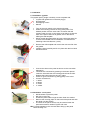
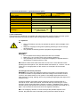
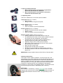
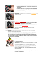
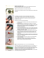
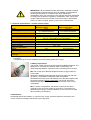
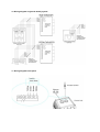
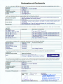
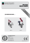
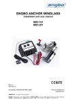
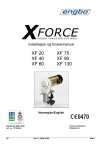
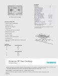
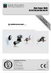
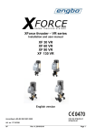
Installation & Maintenance Instructions
•
•
•
•
Joystick- single
Joystick - double
Touch panel
Wireless remote control
NS-EN ISO 9001:2000
FCC ID: R78-RC-01
R78-ECU-01
Art.nr. 117-00155
XF
Rev: 1-2008
Side 1
Contents
Side
1. Introduction........................................................................................................... 3
2. Installation............................................................................................................. 4
2.1 Installation- joystick ....................................................................................................................... 4
2.2 Installation - touch panel ............................................................................................................... 4
3. Technical specifications – joystick and touch panel......................................... 5
4. User instructions .................................................................................................. 5
4.1 Operation....................................................................................................................................... 5
4.2 Intelligent electronic protection...................................................................................................... 5
5. How to operate the thruster ................................................................................. 6
5.1 Optional panels ............................................................................................................................. 6
5.2 Operating instructions. .................................................................................................................. 6
6. Upgrade to wireless remote control.................................................................... 7
6.1 Antenna installation ....................................................................................................................... 7
6.2 Coding the remote control (transmitter and receiver) ................................................................... 8
7. Technical specifications – wireless remote control .......................................... 9
8. Battery replacement ............................................................................................. 9
9. Maintenance .......................................................................................................... 9
10. Wiring diagram single and double joystick .................................................... 10
11. Wiring diagram touch panel ............................................................................ 10
1. Introduction
First of all, we would like to thank you for choosing the XForce Thruster. Engbo AS has for several
years supplied Volvo Penta with thrusters, distributed as QL thrusters through Volvo Penta
dealers and distributors. In late 2006, Engbo and Volvo Penta agreed that distributing through two
channels and brand names would make our thrusters even more available. Together with Engbo
anchoring and mooring systems, the thrusters constitute a complete system for manoeuvring and
mooring your vessel. The control units on both thrusters and winches are based on the same
moduls, which makes it possible to manoeuvre and anchor using one single wireless remote
control.
To achieve maximum benefit from your XForce thruster, please study this manual properly before
installing and making use of the thruster panels. Keep this manual onboard. Do not hesitate to
contact us if you have any questions.
Best regards,
Engbo AS
IMPORTANT:
• Please read the entire instruction carefully before starting on
the installation work.
• The manufacturer does not assume any liability for the
installation of the thruster panels. Qualified installers should
be familiar with these installation instructions. The
responsibility for the installation rests entirely on the installer.
Compliance with regulations must be ensured by the
installer.
• Faulty installation or connection of any components will
render any warranty given by Engbo AS void.
• XForce Thruster(s) must only be operated by persons with
knowledge of the system.
• Keep main engine(s) running when operating thruster(s) to
ensure enough electrical power.
• Only operate the thruster(s) with the propellers fully
submerged.
WARNING:
• Do not operate the thruster(s) without the belt cover installed.
• Make sure no one is within reach of the rotating propeller(s)
• The propeller(s) must come to a stop before engaging in
opposite direction, otherwise the contactors will burn / fuse.
2. Installation
2.1 Installation- joystick
The joystick panel, (single or double), comes complete with;
• Joystick with gasket and connection plug(s)
• Drill template
• Self tapping screws
• Manual
•
•
•
•
•
•
•
•
•
•
•
•
•
Turn off the main switch to the electrical thruster.
Select the mounting position for the joystick panel. The
desired position must be even and in a location that will
prevent water from rain or sea spray to be able to access the
back of the panel. Remove all grease, dust or dirt before
affixing the drill template.
Mount the drill template sticker and use a hole saw and a file
to remove all needed area for installation. Pre-drill the four
fastening holes with Ø2,4mm, (3/32”).
Remove the drill template and remove the red cover film from
the gasket.
Install the panel carefully and fix it in place with the four black
stainless screws.
Connect the wires to the panel as shown on the connection
diagram(s).
The wires are connected by pressing in the button placed
under the hole while the wire is being pushed into the hole.
Release the button when the wire is in place.
Check for good connection by pulling gently in the wires.
Correct connection is;
1: White
2: Brown
3: Green
4: Yellow
2.2 Installation - touch panel
•
•
•
•
Decide where to place the panel.
Drill a Ø 15 mm hole.
Thread the panel cable trough the hole. Clean the surface.
Remove the covering paper on the back of the panel and stick
the panel onto the surface.
• The holes in the panel corners may be used to fasten the
panel with screws if needed. Tighten with care.
NB: For best appearance, be accurate about lining up the panel
before sticking it on.
3. Technical specifications – joystick and touch panel
Joystick
Single/double
Touch panel
Direct connection to control unit.
Power supply
-20 to + 50 degrees Celsius, (-4 to + 122 Fahrenheit)
Operating temperature:
-40 to + 70 degrees Celsius, (-40 to + 158 Fahrenheit)
Storage temperature
Polyester
Panel front material
UV and salt spray resistant Silicone rubber compound
Bellow material
Min. 500 000 cycles
Mechanical endurance
127x53x22 mm
2x62x52
Dimensions (HxWxD):
Environment protection:
(Floating)**
IP 67
Front side exposure, with
gasket installed
IP 68
4. User instructions
These panels are intended for use together with electrical thruster systems. Refer to thruster system
operator instructions and follow all advice and warnings before operating the panels.
4.1 Operation
NB:
• XForce Thruster(s) must only be operated by persons with knowledge of the
system.
• Keep main engine(s) running when operating thruster(s) to ensure enough
electrical power.
• Only operate the thruster(s) with the propellers fully submerged.
Test running:
WARNING:
• Do not operate the thruster(s) without the belt cover installed.
• Make sure no one is within reach of the rotating propeller(s)
• The propeller(s) must come to a stop before engaging in opposite direction,
otherwise the contactors will burn / fuse.
NB: When the boat is launched check that it moves in the correct directions when
operating the control panel. If not, shift the cables connected to no. 1 and no. 3 on the
control unit, or change position on DIL switch 8 on S100 (Ref. XForce thruster
manual).
4.2 Intelligent electronic protection
WARNING: The system has intelligent monitoring to measure run and pause time.
The XForce Thruster is not permitted to start if the voltage on the thruster is below
10.0V on 12V system/ 20.0V on 24V system. If the voltage drops below 9.0/18.0V
when thruster is running, warning will occur by showing orange light power light on the
wireless control.
Of security reasons, the system permits continuous running of the thruster in 4
intervals of 30 sec. After each interval, the thruster will stop. Switching off / on the
joystick or switch panel will make the thruster run again. If repeated 4 times, (total 2
minutes running), the thruster will cool down for 25 minutes before being ready to run
again. This to protect the motor and control unit against overheating.
NB: In an emergency situation, to save the ship at the possible expense of the
thruster, this protection can be override by turning the main switch off and on.
5. How to operate the thruster
•
•
Move / pull the joystick / touch panel to right and the
thruster will be activated to starboard.
Move / pull the joystick / touch panel to left and the
thruster will be activated to port.
5.1 Optional panels
There are 4 different XForce Thruster panels available.
Touch panel (Part no.12-79001)
• Easy to install.
• Designed similar to Engbo winch panel.
Single Joystick (Part no.12-79002)
• ON/OFF switch,
• LEDs for indication of power and direction.
Double joystick (Part no.12-79003)
• Needed if both bow and stern thruster installed.
• ON/OFF switch.
• LEDs for indication of power and direction.
Wireless remote control (Part no.12-47014)
• Floating, splash-proof, hand-held remote control unit.
• The wireless remote control can be used to operate maximum
two thrusters and two windlasses, bow and stern.
• Activates both bow and stern thruster simultaneously in
opposite direction by pushing the centre buttons.
• Operation range of 30 m under normal conditions.
• High quality, narrow band unit with two-way communication
with the electronic control unit.
• Each unit has a unique code.
• Equipped with anti-slip strips on the back.
• Hand/neck cord is included as standard (easily removed).
• The battery lifetime is more than 2 seasons based on normal
leisure use.
IMPORTANT! Always install at least one fixed XForce Thruster panel.
Operating instructions.
The remote control is battery-operated. To ensure longer life, it will
automatically go into sleep mode five minutes after the last button was
released. Deactivation is signalled with two short sound bursts and a
blinking “POWER” indicator. The remote control is activated by holding
down any button for 1.5 seconds. When the remote control has been
activated, the selected thruster can immediately be operated by
pressing the “arrow” button in the desired direction. The thruster will be
running as long as the button is depressed (max. 4x30 sec.)
Green light
NB: Activation is indicated by a steady green light in the “POWER”
indicator and a short sound. All subsequent use of buttons is shown on
the associated indicator above the button, accompanied by a short
sound.
•
•
•
Push the left arrow button, and the thruster moves the boat to
port.
Push the right arrow button, and the thruster pushes the boat
to starboard.
Push the centre (twin arrow) buttons to activate both bow and
stern thruster simultaneously in opposite directions. The boat
will start to rotate about its own axis. (Requires both bow and
stern thrusters installed.)
Orange light
Low voltage at the electronic unit is indicated by an orange light in the
“POWER” indicator.
Red light
The indicator will quickly blink red in case of system faults and
slowly blink red together with short sounds if the remote is unable to
communicate with the electronic unit (out of range.)
If the thruster is overloaded and requires time to cool down, this will
also be indicated by a quickly blink red.
These error messages are shown when buttons are pushed.
6. Upgrade to wireless remote control.
XForce Thrusters can optionally be delivered with 3 different electronic control units (MCU).
1. Relay box
2. Relay box with integrated radio receiver.
3. Transistor-controlled power electronics with integrated radio receiver that replace the
conventional power contactor. (Not yet available, developing process started.)
The new electronic unit contains no open contacts and is very flexible as regards voltage.
The control electronics are software based and feature an integrated radio receiver that
communicates with the wireless remote control and built in system to protect the thruster
motor and electronic components.
IMPORTANT! Turn off the thruster main switch when not in use. The
radio receiver current consumption will be approx 3.5 W as long as it is
turned on.
6.1 Antenna installation
If wireless remote control option is to be implemented after choosing
option 2 or 3.
If not already installed, the MCU must be fitted with an antenna.
The remote control and electronic unit must also be coded/taught
electronically to communicate with each other.
Remove the left rubber cover. Then push the antenna through the
cover (on one side).
While holding down the antenna connector handle, push the antenna
all the way down into the bottom of the clamp. Release the handle and
the antenna is fixed in place.
Replace the rubber cover.
Start by pushing the rubber cover in by the antenna and continue
around the edge until the cover is fixed in place.
Make sure not to twist the cover with the antenna.
(The remote control will function over short distances even without the
antenna.)
6.2 Coding the remote control (transmitter and receiver)
When programming the remote control, both the remote control
(sender) and the receiver in the thruster control unit must be in
programming mode.
Follow the procedure as described below
Picture A
Picture B
Picture C
Picture D
Picture E
1. Choose the pair of buttons on the remote control that is to be
programmed
2. Press both buttons simultaneously for approx 12 seconds.
When a small beep can be heard and the green “power” lamp
starts blinking, the remote control is in programming mode. It
will stay in this mode for 5 min, or until it is finished
programmed (Picture A)
3. Push and hold both buttons down on the mounted panel while
turning on the anchor winch main switch. After the buttons are
released, the receiver will be in programming mode for 10
seconds. (Picture B, C and D)
4. Immediately push and hold one of the buttons (of the chosen
pair) on the remote control until a new beep is heard. The
programming of the remote control and the receiver is now
completed.
5. When releasing the button after programming is complete, the
remote control will turn itself off. To turn it on, press one of the
buttons for 1.5 seconds.
6. Turn off the anchor winch main switch for 5 seconds before
turning it on again.
7. Check that the remote control operates correctly. NB!
Remember to always start with pushing the “down”-button
after the main current has been turned off.
NB! As an alternative way to pt. 3, one can do the following:
Disconnect cables on the mounted panel which are connected to 1, 2
and 3 on the green terminal plug on the control unit. Cut two small
wires (5 cm), and strip approx. 10 mm from their ends. Connect these
between 1 and 2, and also 2 and 3 on the green terminal plug
(Picture E). Turn on the current, and proceed with the
coding/programming as described in pt 4 and 5. Disconnect the small
wires and proceed with pt 6 and 7.
IMPORTANT: When installed in boats approved or classified according
to international or special national rules, the installer is responsible for
following the demands in accordance with these regulations /
classification rules. The instructions in this manual cannot be guaranteed
to comply with all different regulations / classification rules. The remote
control is approved for use in EU/EFTA countries (CE) or US/Canada
(FCC). For other countries, please contact your local authorities.
7. Technical specifications – wireless remote control
Wireless remote:
Model:
Power supply:
Battery life:
Communication:
Operating frequency:
Channels:
Channel separation:
Address range:
Temperature range:
Relative humidity
(without condensation):
Weight:
Dimensions (HxWxD):
Environment protection:
(Floating)**
Motor Control Unit:
RC-01
ECU-01
3 x 1.5 V DC
(3 x AAA/LR03 batteries)
From thruster (integrated)
2–3 years (normal leisure use)
Not applicable
Two-way, narrowband, GFSK modulation
868.075 – 869.125 MHz, CE (EU/EFTA)*
902.175 – 903.025 MHz, FCC (US/Canada)*
16 for communication
50 kHz
65.535 (16 bit), spread among the 16 channels
-20 to +60 degrees Celsius/-4 to +131 degrees Fahrenheit
20% – 90%
105 g
127x53x22 mm
Model dependent
Model dependent
IP 68
IP 41
*May apply to other countries. For information, please contact local authorities for the country
concerned.
**Conditional upon correct installation and intact rubber gasket and O-rings.
8. Battery replacement
The remote control uses three regular AAA/LR03 alkaline batteries. The
battery life is more than two seasons under normal leisure use.
When replacing batteries, open the unit by unscrewing all five screws.
NB: The screws are of different lengths and have O-rings under the
screw heads.
Replace the batteries and make sure all point the same way with the +
up and the – downwards towards the edge as illustrated.
Reassemble the back cover and carefully screw the parts together until
the housing gasket is lightly compressed. The remote will remain
waterproof as long as the O-rings and gasket are intact with correct
compression.
NB: To ensure a long lifetime, this remote control has acid-proof
machine screws and screw inserts in the housing. The screws may
penetrate the housing if screwed carelessly or too much force is used.
(Not covered by the warranty.)
9. Maintenance
Periodically before each season, or minimum once a year, check the electrical connections and
correct function according to the thruster user instructions.
10. Wiring diagram single and double joystick
11. Wiring diagram touch panel