1
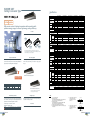
MITSUBISHI ELECTRIC MULTIPLE SPLIT TYPE AIR CONDITIONERS
Series
CITY MULTI
Eco Changes is the Mitsubishi Electric Group’s environmental statement,
and expresses the Group’s stance on environmental management.
Through a wide range of businesses, we are helping contribute to the
realization of a sustainable society.
The Air Conditioning & Refrigeration Systems Works acquired ISO 9001 certification under Series
9000 of the International Standard Organization (ISO) based on a review of Quality management for
the production of refrigeration and air conditioning equipment.
ISO Authorization System
The ISO 9000 series is a plant authorization system relating to quality management as stipulated by
the ISO. ISO 9001 certifies quality management based on the "design, development, production,
installation and auxiliary services" for products built at an authorized plant.
FM33568 / ISO 9001;2008
The Air Conditioning & Refrigeration Systems Works acquired environmental management system
standard ISO 14001 certification.
The ISO 14000 series is a set of standards applying to environmental protection set by the
International Standard Organization (ISO).
Registered on March 10, 1998.
Warning
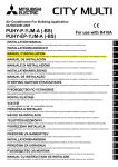
■ Do not use refrigerant other than the type indicated in the manuals provided with the unit and on the nameplate.
- Doing so may cause the unit or pipes to burst, or result in explosion or fire during use, during repair, or at the time of disposal of the
unit.
- It may also be in violation of applicable laws.
- MITSUBISHI ELECTRIC CORPORATION cannot be held responsible for malfunctions or accidents resulting from the use of the wrong
type of refrigerant.
http://Global.MitsubishiElectric.com
MEE11K010
CM11AS-
New publication effective Oct. 2011
Specifications subject to change without notice
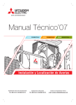
Air conditioning is an ideal way of controlling the temperature, movement and
cleanliness of air inside any building, large or small. With today's buildings being so
well insulated and increasingly full of electronic equipment, the need for effective
climate control is greater than ever. Not only does it cool in the summer months, but
air conditioning can also heat, doing away with the need for separate heating systems
altogether. More and more people today are enjoying the benefits of comfortable
working and living environments made possible with air conditioning.
Unsurpassed air conditioning
from Mitsubishi Electric
Known the world over, Mitsubishi
Our Latest Technologies
Electric is a trusted household name
associated with a variety of products
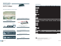
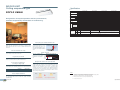
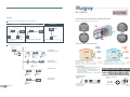
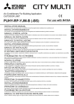
V RF system
VRF stands for Variable Refrigerant Flow.
A VRF air conditioning system modulates the
flow of refrigerant depending upon the capacity
requirements of the building. In its simplest
form, a VRF system comprises an air-cooled
outdoor unit and a series of indoor units that
regulate the air temperature inside an internal
space.
I
ntelligent Power Module (IPM)
technology
Features of Mitsubishi Electric
air conditioners
Page 1-10
Remote Controller
Page 11-30
Indoor unit
Page 31-70
Electric, quickly rose to the forefront of
Outdoor unit
Page 71-94
the air conditioning industry - a
Optional parts
Page 95-98
and services. Founded in 1920, the
company known today as Mitsubishi
The CITY MULTI range from Mitsubishi Electric
provides precise control of energy input,
through utilization of its Intelligent Power
Module (IPM) technology. By employing this
technology, highly efficient operation is possible
with compact units closely matching building
requirements.
Contents
position we still enjoy today. We pride
ourselves on offering some of the
I
nverter driven technology
At Mitsubishi Electric we strive to continually
meet the increasing demands of our customers,
being the first in the industry to offer highly
advanced ‘inverter driven’ systems. Using
inverter technology our systems produce just
the right amount of output to match the exact
requirement of any building. These systems
work so efficiently that they don’t waste
valuable
energy
by
over-heating
or
over-cooling, resulting in greatly reduced
running costs. Alternative systems that may
appear cheaper, can often cost substantially
more to run, making us the most cost effective
choice all round.
Page 1
R 410A refrigerant
most
energy
efficient
As scientific evidence points to man-made
chemicals for the damage caused to the ozone
layer, we only use chlorine-free refrigerants
that are safe with zero ODP (Ozone Depletion
Potential). Accordingly, our systems require
less energy to run, and have a significantly
lower indirect global warming potential. In
short, we produce the most efficient equipment
possible, while helping to protect the environment.
available on the market.
systems
Page 2
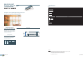
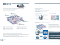
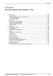
V RF system
Our answer to VRF
Mitsubishi Electric sets the boundaries of VRF technology with the CITY MULTI range, which is available using
R410A refrigerant with zero ODP (Ozone Depletion Potential). The range has been specifically designed for
today’s building requirements and addresses key market issues such as energy efficiency, adaptability and
reliability. With user friendly control systems utilizing internet technology and integrated cooling and ventilation
indoor units, CITY MULTI is the benchmark and market leader in VRF technology.
VRF is a multi and direct expansion type air conditioning system where by one outdoor unit can be connected with
multiples indoor units. The amount of refrigerant can be regulated freely according to the load on the indoor unit by
the inverter driven compressor in the outdoor unit. Zoning in a small office is possible with a small capacity indoor
unit. Energy conservation is easily handled because individual indoor units can stop and start their operation as
needed. There are various indoor units available in order to suit various interior design needs.
Inverter driven compressor
Sophisticated
yet simple technology
Outdoor unit
Joint
Header
Reliable
Designed and manufactured to the highest standards, the
CITY MULTI range offers one of the most reliable air
conditioning systems available. Simple to install and easy to
maintain, this range provides ideal solutions you can trust to
protect your investment.
Indoor unit
OFF
PEFY-VMS1
ON 27°c
ON 25°c
ON 25°c
ON 26°c
OFF
ON 23°c
Controller
PEFY-VMR
PFFY-VKM
>All the CITY MULTI outdoor units are made under stringent control.
Page 3
Page 4
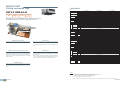
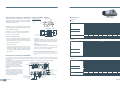
I nverter Driven Compressor
Technology - now up to 50HP
Low
Starting
Currents
Using inverter driven technology
saves energy for several reasons:
The compressor varies its speed to match the indoor cooling or heating demand and therefore only consumes the
energy that is required.
When an inverter driven system is operating at partial load, the energy
efficiency of the system is significantly higher than that of a standard fixed
speed, non inverter system.
The fixed speed system can only operate at 100%, however, partial load
conditions prevail for the majority of the time. Therefore fixed speed
systems cannot match the annual efficiencies of inverter driven systems.
Heating / Cooling Capacity
100%
Linear Capacity
Control
15%
Using proven single inverter driven compressor technology, the CITY
MULTI range is favored by the industry for low starting currents (only 8 amps
for a 16HP YHA/YJM-A outdoor unit), and smooth transition across the range of
compressor frequencies.
Unbeatable Efficiency
15Hz
Cooling:74Hz
Heating:81Hz
Compressor Frequency
* image
* The values vary depending on the actual
conditions such as ambient temperature.
All CITY MULTI compressors are inverter-driven type.
-Capable of precisely matching a building's cooling and heating demands.
Heat Interchange Circuit
The unique Heat Interchange Circuit (HIC) enhances efficiency by providing additional sub-cooling and allows the
expansion device to effectively control the refrigerant distribution, thereby increasing the operating efficiency and
reducing the volume of refrigerant in each system.
CITY MULTI Refrigerant Circuit
Common Refrigerant Circuit
Condenser
The outdoor unit combinations comprise 1 unit for 8-18HP systems, 2 units for 20-36HP systems and 3 units for
38-50HP systems. Each unit carries one inverter compressor making simple and highly reliable control possible.
Not only does it allow low starting currents, the inverter-driven compressor also provides precise indoor comfort
and adapts to the air conditioning load.
Stable and smooth operation
Condenser
Y series 8-18HP
Y series 20-36HP
High temperature
Compressor
Heat exchanger
Accumulator
100%
100%
3 inverter compressors
1 inverter compressor
LEV
2 inverter compressors
Accumulator
No2
Inverter
No1
load
Page 5
LEV
Evaporator
No3
No2
Medium temperature
Bypass
Evaporator
Y series 38-50HP
100%
capacity
Compressor
Supercooled
heat exchanger
Low temperature
capacity
capacity
No1
load
No1
No1
No2
No1
load
LEV
Page 6
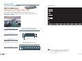
I ntelligent Power Module (IPM)
Technology
The YHA range from Mitsubishi Electric provides precise control of energy input, through utilization of its Intelligent
Power Module (IPM) technology. By employing this technology it is possible to closely match the building
requirements, achieving more accurate control of the occupied space. By using incremental 1Hz steps of capacity
control, the amount of power input required is significantly reduced, resulting in greatly improved COP’s.
In addition, IPM technology ensures effective performance under partial load conditions, a condition that most
systems will be in for the majority of the normal working life cycle. By taking account the efficiency at both part
load, and peak load conditions, R410A CITY MULTI is designed to provide unbeatable year round/seasonal
efficiency.
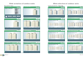
The difference between YHA/YJM-A and
previous Mitsubishi Electric models
Total Energy Conservation
Technology is key when increased efficiency is demanded.
The CITY MULTI YHA/YJM-A range is able to deliver this in simple ways.
A highly efficient R410A scroll compressor design results in less friction losses at the motor. A simplified refrigerant
circuit (low pressure loss) including a new accumulator design also adds a few more points to the efficiency scale.
Enhancements to the heat interchange circuit, an inverter driven fan motor and a heat exchanger design again add
vital increases to overall system efficiencies and COPs.
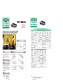
Comparison of COP (energy efficiency) – 8HP system
COP
5.0
The importance of COP
4.5
56%
4.0
Energy
Saving
41%
Energy Saving
3.5
4.45
4.02
3.0
2.5
High COP (Coefficient of Performance)
is realized
2.86
COP stands for “Coefficient of Performance”. It is a measure of the useful energy a system can deliver compared
to the energy it consumes. It is calculated by dividing the energy output by the energy input of a system. The
higher the figure then the more efficient the system is deemed to be. Mitsubishi Electric VRF models, the world's
highest energy-efficient air-conditioners, will undoubtedly reduce millions of tons of CO2 emissions.
2.0
0
R22
Our equivalent product
10 years ago, PUHY-200YMF
Standard model
PUHY-P200YHA
High COP model
PUHY-EP200YJM-A
* Average COP of cooling / heating
* The values were obtained under the standard conditions.
Page 7
Page 8
E fficient R410A refrigerant
History of refrigerant
R22, an HCFC-based refrigerant, has been a popular choice for most chillers. R22 has been targeted by the
Montreal Protocol to be phased out in new equipment. Additionally, governments in many countries are enforcing a
ban of HCFC-based refrigerants for new installations.
Because of these restrictions, R410A refrigerants are desirable. R410A is a blend of HFCs, which do not deplete
the ozone.
Technical aspects of refrigerant
For the Environment
R410A is a more efficient refrigerant as it has a higher specific heat capacity when compared to R407C or R22.
This higher energy carrying capacity allows for smaller pipe sizes, longer pipe runs and reduces the volume of
refrigerant within a system. This is a major factor when concerning safety and environmental requirements in the
design, manufacture, installation, operation, maintenance and disposal or refrigerating systems.
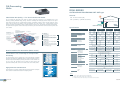
New Design
Reduction of operation noise
Enhancing environmental care (measures for the RoHS Directive and the refrigerant reduction)
Every unit is in compliance with the RoHS Directive,* which stands for the Restriction of Hazardous Substances:
Lead-free soldering is used to avoid Lead Groundwater Contamination on the print board. The amount of
refrigerant on the unit has also been reduced to enhance environmental care.
* RoHS Directive: the restriction of the use of certain hazardous substances in electrical and electronic equipment that has been sold in EU since July 2006
Improvement of COP
Improvement of COP
Photo : Y series
Improvement of reliability and
easy maintenance
Page 9
Page 10
The importance of control
The need for control is paramount in order
to optimise the performance of any air
conditioning system and minimize its
running costs. Mitsubishi Electric offers a
wide range of control options designed to
meet such needs.
Operating an air conditioning system without
the right control can prove costly. It's therefore
important to ensure that every system is
correctly specified to the degree of control it
requires. Mitsubishi Electric have a wide range
of controls available 'off-the-shelf' and
individual control systems can be specifically
designed to match.
A degree of difference
When an air conditioning system is not
properly controlled, it will not run as efficiently
as it should. For every degree that the system
deviates from the required temperature,
energy costs can rise by up to 5%. Specify one
of the many control options from Mitsubishi
Electric to ensure air conditioning works as
intended, whilst giving the optimum amount of
control.
The simpler, the better
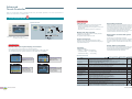
R emote Controller
Individual Remote Controller
Good controls will benefit any application,
large or small. Air conditioning products need
to react to a variety of factors: different room
sizes, usage and staff levels; changes in the
climate; electronic equipment and lighting ...the
list goes on. So whatever the application,
optimum control of air conditioning systems is
essential and will result in a constant,
comfortable environment, which in turn is both
energy and cost efficient.
With the array of comprehensive control
systems available from Mitsubishi Electric, it
becomes simple to design and install air
conditioning systems. From a simple
hand-held controller to a AG-150A system you are in control.
Centralized Remote Controller
Remote Controller
Page 11
Page 12
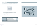
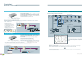
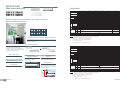
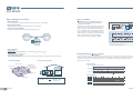
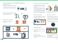
Integrated Communications Control with
Mitsubishi Electric's Unique Transmission Network (M-NET)
System Controller
MITSUBISHI ELECTRIC's Air-conditioner Network System (MELANS) leads air conditioner management a PC
browser and Network era.
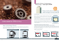
MELANS
Use of our MELANS products enhances EFFICIENCY and QUALITY of air-conditioning, contributing to
ENERGY SAVING and reduction in running cost. We offer a wide variety of MELANS products to meet all
requirements - from the smallest and simplest to the largest and most complex.
We have individual remote controllers, various centralized controllers, and centralized integrated software, as
well as BMS interface hardware and software etc. Above all, with AG-150A/GB-50ADA, PC browser and long
distance remote control (monitoring and operating) via communication Network is possible and easy.
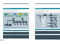
I
C entralized Remote Controller
ndividual Remote Controller
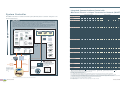
All of the local remote controllers feature liquid
crystal and LED displays and easy to operate.
M-NET
Remote
Controller
Simple
Remote
Controller
Wireless
Remote
Controller
AG-150A
PAC-YT51CRB
PAC-SE51CRA
PAC-YG50ECA
Advanced
Touch
Controller
PAR-30MAA
PAR-21MAA
PAR-FL32MA PAR-FA32MA
GB-50ADA
ON/OFF
Remote
Controller
AT-50A
PAC-YT40ANRA
PI Controller
PAR-F27MEA
PAR-SA9FA-E
PAR-SL94B-E
PAC-YG60MCA
DIDO Controller
OUTDOOR UNIT
S
Y
:PUMY
:PUHY
INDOOR UNIT
PEFY
PMFY
PLFY
PCFY
PKFY
PFFY
PAC-YG66DCA
AI Controller
Interface
BAC-HD150
Interface
PAC-YG63MCA
LMAP02
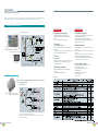
A ir-Conditioning
Control System
BACnet
transmission line
(Ethernet)
This is a specialized air conditioning management system, in which
up to 2000 indoor units can be
centrally controlled.
LONWORKS
transmission line
Integrated centralized
control software
TG-2000A
MITSUBISHI ELECTRIC's
CITY MULTI can be easily
connected to the building
managementsystem through
BACnet .
*Some controllers cannot be used in combination with certain models of devices.
Page 13
"#
"#
"#
76<:744*+4.:7=8;6-77:; :7=86-77:
C!8.:*<260
! !
7-.,7741.*<-:A/*6
%.58.:*<=:.;.<
7,*4".:52<":712+2<
*6;8..2:/47?-2:.,<276
C$<*<=;5762<7:260
! !
7-.,7741.*<-:A/*6
%.58.:*<=:.;.<
7,*4".:52<":712+2<
*6;8..2:/47?-2:.,<276
6-77:<.58.:*<=:.
24<.:;206
::7:/4*;1260
::7:,7-.
!8.:*<27617=:
C$,1.-=4260
!6.-*A
%25.;7/! !8.:-*A
(..34A
%25.;7/! !8.:?..3 @ @
66=*4
!8<252B.-;<*:<=8
=<77//<25.:
26<25.:;.<<260=62<526=<.
C#.,7:-260
::7::.,7:*24A576<14A:.87:<
4.,<:2,2<A,1*:0.
C!<1.:
%.58;.<4252<*<276+A7,*4#
%.58;.<4252<*<276+A$A;<.5,76<:744.:
$A;<.5,76<:744.:
"
"
"#
"
)%# $# )%
#
%
")
%
:7?;.: :7?;.: :7?;.:
@ @ @ @ @
=<747,3
201<;.<+*,3
$42-260<.58.:*<=:.,76<:74
C*6*0.5.6<:7=86<.:47,3.-
'.6<24*<27626<.:47,3
:7=8;.<<260
47,3;.<<260
#.>2;2767/.4.,<:2,2<A,1*:0.
C!8.:*<26076!$$ )26<.:47,3.-:7=86<.:47,3.-
! !
*6;8.. '.6<24*<27657-.
C$<*<=;5762<7:26076!$$ )26<.:47,3.-:7=86<.:47,3.-
! !
*6;8.. '.6<24*<27657-.
@
@
*,10:7=8*<,1.-
*,10:7=8
47,3/7:%)&%6-77:=62<67</7:*44:$
42,.6;.:.02;<:*<27687;;2+4.
2,.6;.:.02;<:*<276/7:<1.78<276*4/=6,<276;:.9=2:. 7<>*24*+4. 7<&;.-
*<,1.-764A
*<,1.-1*6-4260/7:5*26<.6*6,.
47,3
Ethernet
Remote Controller
7,*4:.57<.,76<:744.:
7-.4
Integrated centralized
control software TG-2000A
:7=8;.<<260>2*?2:260+.<?..66-77:=62<;?2<1,:7;;7>.:,*+4.
6;<*44*<27687;;2+4.*<62<2*4;.<<260?.++:7?;.:
6<.:47,32;;.<*<7,*4:.57<.,76<:744.:
42,.6;.:.02;<:*<276<7
2;:.9=2:.-<75762<7:*6-78.:*<.<1.=62<;+A+:7?;.:*6-%
,766.,<.-?2<1")
2;,758*<2+4.?2<1%
'.:7:4*<.:
2;,758*<2+4.?2<1%
'.:7:4*<.:
%12;/=6,<276,*6+.;.<764A76<1.$2584.:.57<.,76<:744.:%12;/=6,<276,*667<+.=;.-?2<1<1.$2584.:.57<.,76<:744.:
=<<1.>*42-2<A7/<12;/=6,<276?2<1<1.$2584.:.57<.,76<:744.:-.8.6-;76<1.26-77:=62<57-.4*6-<1.:.*:.87;;2+242<2.;<1*<<12;/=6,<276,*6+.=;.-?2<1<1.5
%12;/=6,<2762;*>*24*+4.764A?1.6*884A260<70.<1.:?2<1%
*6-
6<.:47,32;;.</:75;A;<.5,76<:744.:@,.8<")%
#
%1.5*@25=56=5+.:7/,76<:744*+4.=62<;-.,:.*;.;-.8.6-26076<1.26-77:=62<57-.4
7:26-77:=;.764A
Remote Controller
Page 14
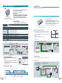
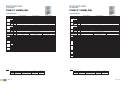
Individual
Remote Controller
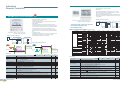
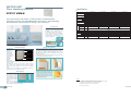
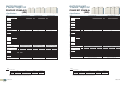
Wired MA remote controller PAR-21MAA
Wired MA remote controller PAR-30MAA
• Set temperature in 1°C/°F increment
• Weekly timer
Up to 8 ON/OFF/temperature setting per day in 1 minute
increment. Setting kept in nonvolatile memory. No need to
worry about re-setting at power failure.
• Room temperature control with thermostat sensor inside the unit
• Self-diagnosis function immediately informs error code in case
of malfunction
NEW
• Backlit LCD (Liquid Crystal Display)
Large, easy-to-see display
Full-dot LCD display with large characters for easy viewing
Contrast also adjustable
• Night Setback
To prevent indoor dew or excessive temperature rise, this
control starts heating operation when the control object group
is stopped and the room temperature drops below the preset
lower limit temperature. Also, this control starts cooling
operation when the control object group is stopped and the
room temperature rises above the preset upper limit temperature.
• Language selection
Language to be displayed on the screen can be selected from
eight languages: English, French, German, Spanish,
Italian,Portuguese, Swedish, and Russian.
"#($#(453B-453=-4<""
7627B-7627=-627#
Example of system configuration
Example of system configuration
Dimensions: 130(W) x 120(H) x 19(D) mm
: 5-1/8(W) x 4-23/32(H) x 3/4(D) in.
M-NET
Multi-language Display Example
Language
English
Non-polarized
2-wire
Non-polarized
2-wire
• New display-Larger, easier-to-see characters
• Dot Liquid Crystal Display (LCD)
• Multi-language Display
MA remote controller
MA remote controller
[Dot display table]
German
Spanish
Russian
Italian
Chinese
French
Japanese
Waiting for start-up
Operation mode
Cool
Dry
Heat
Auto
M-NET
Auto(Cool)
Non-polarized
2-wire
MA remote controller
Auto(Heat)
Non-polarized
2-wire
Fan
MA remote controller
*When a PAR-30MAA is connected to a group, no other MA
remote controllers can be connected to the same group.
Ventilation
Stand by
(Hot adjust)
Defrost
Cooling
Heating
Room temp.
21°C
Heating
ON
Heating
OFF
) $%')$#()')(
,#)#$$'
)"%')*''$%(!$,
)!$,'!")*'#
() $#)'$!)"
) $%')$#()$%(
,#)#$$')"%')*'
'((6F
$+)!$,'!")
?
,#)$#)'$!)"($+'
Lower limit temp.
12°C
@%%'!"))"%
5;F
)() $%')$#
Not use button
Cooling
OFF
Cooling
$$")"%
57F
Night setback operation
Setback control time
ON
Check (Error)
) $%')$#()')(
,#))"%')*'
-()*%%'!")
*'#() $#)'$!)"
) $%')$#()$%(
,#))"%')*''$%(
6F
!$,)*%%'!")
?
,#)$#)'$!)"($+'
Test run
Self check
Setback control time
Unit function selection
Functions
Setting of ventilation
*#)'ޓ$*%'ޓ$*%$'$!!)+$)+!!
Item
?2?
?%')$#"$(,)#
$$")"%
())#
'!$,')$#())#
$*+'())#
A#)!)$#&*%"#)$#)'$!
''$'#$'")$#
"'
!!$,(2(!!$,(!$!$%')$#
?%')$#!$
"%')*''#'()')$#
*)$')*'#
Remote Controller
Page 15
Description
Setting
Display
Functions
,)(),#?#?
,)("$#
$$!2'.2#2*)$2=)
)"%')*'#(),)#)$!!$,#'#
$$!2'.4<F
63F
29:F;:F
=) 4:F
5;F
296F;6F
*)$4<F
5;F
29:F;6F
1))"%')*''#+'(%##$#)"$!
#('!$,')$#
1+!!'!$,')$#(+'.%##$#)"$!
,)(),#!$*+'?2?
#)'!$ ())###)'!$ $%')$#())#,))
D>@?D*#)(#"
)$%2$,2=())#($)+#)!)$#&*%"#)#$#)'$!!
B##''$'$*'(#''$'$#)*#)'((%%'
'$#)$##*#)"$!('!#*"'#$#))#*"'#())$%%',##''$'$*'(
#$'")$#$+#()$#)'#+#
1#''$'$".#$)%%'%##$#)''$'
?2?)"'
*'#(?#?!.)())"
/"#()#8"#*)#'"#)(
/)(!($%$((!)$())?)"$#!.$')?)"$#!.
*)$?)"'
*'#($)*#))'')#%'$$$%')$#
/?%')$#)"#())$+!*'$"63)$573#43"#*)#'"#)(
$!!$,#$%')$##%'$)." #')#())#($#)#)'!E$#)'$!!'?2?
$%')$#"$())#)"%')*'())##!)'(#'()
1B!#$%')$#(%'$))$%')$#$#!)(*%$#!.$#)>#(%!.#)0*!!0"$
$!!$,#$%')$##%'$)'(%)+!.?2?$%')$#"$())#)"%')*'())##
'!$,')$#())#
'$$")"%')*''#$'$%')$#"$#'()')
*#)($%')))%'())"%')*')'(#)%'$
"#())$+!*'$"63)$453#43"#*)#'"#)(
1$)+!,#))"%')*'())#'#('()')
: Each unit
Item
ON/OFF
Operation mode switching
Temperature setting
G
Fan speed setting
Air flow direction setting
Permit / Prohibit local operation
Prohibition/permission of specified mode
(Cooling prohibited/heating prohibited
/cooling-heating prohibited)
C
Error
Ventilation equipment
Set temperature range limit
C
Auto lock function
ޓ: Each group ޓ
: Group or collective
Description
: Not available
Operations Display
ON and OFF operation for a single group
Switches between Cool / Dry / Auto* / Fan / Heat. Operation modes vary depending on the air conditioner unit.
* Auto only supported for the CITY MULTI R2 and WR2 series.
Sets the temperature for a single group
Range of temperature setting
Cool/Dry : 19°C - 30°C (14°C - 30°C) / 67°F - 87°F (57°F - 87°F)
Heat
: 17°C - 28°C (17°C - 28°C) / 63°F - 83°F (63°F - 83°F)
Auto
: 19°C - 28°C (17°C - 28°C) / 67°F - 83°F (63°F - 83°F)
( ) For PEFY/PFFY by setting DipSW 7-1 to ON and limits to NI6H fan speed only.
Models with 4 air flow speed settings: Hi/Mid-2/Mid-1/Low
Models with 3 air flow speed settings: Hi/Mid/Low
Models with 2 air flow speed settings: Hi/Low
Fan speed setting (including Auto) varies depending on the model.
Air flow direction angles (4-angle, or 5-angle Swing) Auto Louver ON/OFF
Air flow direction settings vary depending on the model.
Individually prohibit operation of each local remote control function (ON/OFF, Change operation mode, Set
temperature, Reset filter).*1: When the local remote controller inactivation command is received from the main
system controller, "
" is displayed.
X
By the setting from System Controller, the operation for the following modes is prohibited.
At cooling prohibited : Coo l, Dry, Auto,
At heating prohibited : Heat, Auto,
At cooling-heating prohibited : Cool, Heat, Dry, Auto
When an error is currently occurring on an air conditioner unit, the afflicted unit and the error code are displayed.
Up to 16 indoor units can be connected to an interlocked system that has one LOSSNAY. LOSSNAY items that can
be set are "Hi" "Low" "Stop". Ventilation mode switching is not available.
Set temperature range limit to cooling, heating, or auto mode.
Setting/releasing of simplified locking for remote control switch can be performed.
· Locking of all switches · Locking of all switches except ON/OFF switch
*1
X
X
Remote Controller
Page 16
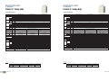
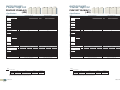
Wireless remote controller PAR-FL32MA / PAR-FA32MA / PAR-SA9FA
Wired ME remote controller PAR-F27MEA
• This remote control requires non-polar wiring to only one indoor unit.
• Group operation over multiple outdoor units is possible. Grouping can be changed without re-wiring, which makes dividing
rooms for tenants easier.
• LCD temperature setting and display in 1°C/1°F increments.
Example of
system configuration
Dimensions: 130(W) x 120(H) x 19(D) mm
: 5-1/8(W) x 4-23/32(H) x 3/4(D) in.
ME R/C
Functions
: Each unit
Item
ON/OFF
Operation mode switching
Temperature setting
Fan speed setting
ޓ: Each group ޓ
ME R/C
: Group or collective
Description
Air flow direction angles (4-angle, Swing) Louver ON/OFF
Air flow direction settings vary depending on the model.
Permit / Prohibit local operation
Individually prohibit operation of each local remote control function (ON/OFF, Change operation mode, Set
temperature, Reset filter). *1: When the local remote controller inactivation command is received from the master
system controller, "-CENTRALLY CONTROLLED-" is displayed.
Timer operation
Ventilation equipment
Set temperature range limit
Auto lock function
PAR-FL32MA
PAR-FA32MA
Dimensions: 58(W) x 159(H) x 19(D) mm
: 2-5/16(W) x 6-5/16(H) x 3/4(D) in.
ON and OFF operation for a single group
Switches between Cool / Dry / Auto / Fan / Heat. Operation modes vary depending on the air conditioner unit.
Auto mode the CITY MULTI R2 and WR2 series only.
Sets the temperature for a single group
Range of temperature setting
Cool/Dry : 19°C - 30°C (14°C - 30°C), Heat: 17°C - 28°C (17°C - 28°C), Auto: 19°C - 28°C (17°C - 28°C)
Models with 4 air flow speed settings: Hi/Mid-2/Mid-1/Low
Models with 3 air flow speed settings: Hi/Mid/Low
Models with 2 air flow speed settings: Hi/Low
Fan speed setting varies depending on the model.
Air flow direction setting
Prohibition/permission of specified mode
(Cooling prohibited/heating prohibited
/cooling-heating prohibited)
Error
: Not available
Operations Display
By the setting from System Controller, the operation for the following modes is prohibited.
At cooling prohibited : Cool, Dry, Auto, At heating prohibited : Heat, Auto,
At cooling-heating prohibited : Cool, Heat, Dry, Auto
When an error is currently occurring on an air conditioner unit, the afflicted unit and the error code are displayed.
Thanks to the three timer modes equipped, a proper mode can be selected to mee the usage.
One day timer
: ON/OFF setting of one time on one day can be applied.
Daily timer
: ON/OFF setting by the One day timer can be reperted for everyday.
Auto OFF timer : OFF timer can be set in a range from 30 minutes to 4 hours.
* Setting of Auto OFF timer automatically activates OFF timer at the next operation. This function can be utilized
to prevent the negligence of OFF setting.
Up to 16 indoor units can be connected to an interlocked system that has one LOSSNAY. LOSSNAY items that can
be set are "Hi" "Low" "Stop". Ventilation mode switching is not available.
Set temperature range limit to cooling, heating, or auto mode.
Setting/releasing of simplified locking for remote control switch can be performed.
· Locking of all switches · Locking of all switches except ON/OFF switch
Dimensions: 70(W) x 120(H) x 22.5(D) mm
: 2-3/4(W) x 4-3/4(H) x 7/8(D) in.
*1
X
PAR-SL94B-E
(Wireless remote controller kit for ceiling suspended)
X
PAR-SA9FA-E
(4-way Cassette signal receiver)
X
Dimensions: 256(H) x 19(D) mm
Dimensions: 182(W) x 57(H) x 31(D) mm
• No need to configure addresses for group operation.
• Lit LED keeps you informed of operation - blinking even gives you the error code via the number of blinks.
• Can be used with the MA remote controller.
*When used in group configurations, wiring between indoor units is required.
*Combining ME remote controller and/or LOSSNAY remote controller in a group is not possible.
• LCD temperature setting and display in 1°C /1°F increments.
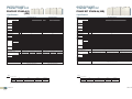
Simple remote controller PAC-YT51CRB (MA)
• The only wiring required is cross-over wiring based on two-wire signal lines.
• Room temperature sensors are built-in.
• LCD temperature setting and display in 1°C/1°F increments.
• Can operate all types of indoor units
*Since this controller has limited functions, it should always be used in conjunction
with standard controller or centralized controller.
Example of system configuration
receiver
PAR-SA9FA
Non-polarized
2-wire
Signal
receiving
unit
PLFY-P VCM/VLMD
PFFY-P VKM
PEFY-P VMR-E-L/R/VMH
PFFY-P VLEM/VKM/VLRM/VLRMM
PAR-SL94B-E
Wireless
remote
controller
Wireless
remote
controller
PAR-FA32MA
Simple MA R/C
: Each unit
Item
Operation mode switching
Temperature setting
Fan speed setting
Permit / Prohibit local operation
Error
Ventilation equipment
Set temperature range limit
Remote Controller
Page 17
PAR-FA32MA
PAR-SL94B-E
PLFY-P VBM-E
PAR-SA9FA-E
PAR-SA9FA-E
PKFY-P VHM/VKM
PAR-SL94B-E
Built-in
Power supply unit
(PAC-SC51KUA)
Functions
ON/OFF
PAR-FL32MA
PCFY-P VKM
PKFY-P VBM-E
24VDC
Dimensions: 70(W) x 120(H) x 41(D) mm
: 2-3/4(W) x 4-23/32(H) x 1-5/8(D) in.
PAR-FA32MA
PEFY-P VMS1(L)
PEFY-VMA(L)
Wireless
remote
controller
Centralized
controller
transmitter
PMFY-P VBM
Signal
receiving
unit
Signal
receiving
unit
Example of system configuration
PAC-YT51CRB
Correspondence table
ޓ: Each group ޓ
: Group or collective
Description
ON and OFF operation for a single group
Switches between Cool / Dry / Auto* / Fan / Heat. Operation modes vary depending on the air conditioner unit.
* Auto only supported for the CITY MULTI R2 and WR2 series.
Sets the temperature for a single group
Range of temperature setting
Cool/Dry : 19°C - 30°C (14°C - 30°C) / 67°F - 87°F (57°F - 87°F)
Heat
: 17°C - 28°C (17°C - 28°C) / 63°F - 83°F (63°F - 83°F)
Auto
: 19°C - 28°C (17°C - 28°C) / 67°F - 83°F (63°F - 83°F)
Models with 4 air flow speed settings: Hi/Mid-2/Mid-1/Low
Models with 3 air flow speed settings: Hi/Mid/Low
Models with 2 air flow speed settings: Hi/Low
Fan speed setting (including Auto) varies depending on the model.
Individually prohibit operation of each local remote control function (ON/OFF, Set temperature). *1: When the local
remote controller inactivation command is received from the main system controller, "CENTRAL" is displayed.
When an error is currently occurring on an air conditioner unit, the afflicted unit and the error code are displayed.
Up to 16 indoor units can be connected to an interlocked system that has one LOSSNAY.
Set temperature range limit to cooling, heating, or auto mode.
Simple MA R/C
Functions
: Each unit
: Not available
Operations Display
Item
ON/OFF
Temperature setting
Air flow direction setting
Timer operation
*1
X
X
Permit / Prohibit local operation
Ventilation equipment
X
ޓ: Each group ޓ
: Group or collective
Description
ON and OFF operation for a single group
Sets the temperature for a single group
Range of temperature setting
Cool/Dry : 19°C - 30°C (14°C - 30°C) / 67°F - 87°F (57°F - 87°F)
Heat
: 17°C - 28°C (17°C - 28°C) / 63°F - 83°F (63°F - 83°F)
Auto
: 19°C - 28°C (17°C - 28°C) / 67°F - 83°F (63°F - 83°F)
( ) For PEFY/PFFY by setting DipSW 7-1 to ON and limits to NI6H fan speed only.
* Set to PAR-FL32MA according to its Installation Manual 4 "Model setting".
Air flow direction angles (4-angle, Swing) Auto Louver ON/OFF.
Air flow direction settings vary depending on the model.
One ON/OFF setting can be set for one day.
Individually prohibit operation of each local remote control function (ON/OFF, Change operation mode, Set
temperature, Reset filter).
*1 If operation is performed when the local remote controller inactivation command is received from the main system
controller, a buzzer will ring and an LED will flash.
Up to 16 indoor units can be connected to an interlocked system that has one LOSSNAY.
: Not available
Operations Display
*1
X
X
X
Some models will have different display for the air flowdirection and fan speed.
Set the air flow direction and fan speed when performing initial setting.
Remote Controller
Page 18
Advanced
Touch Controller
With our new Advanced Touch Controller AT-50A, easy and simple operation on the touch panel offers an
optimal air environment for individual unit.
Touch controller AT-50A
NEW
New Functions
System structure
M-NET
M-NET
M-NET
adapter
AT-50A
Power supply unit
PAC-SC51KUA-J
Three in One
Night setback function
%""%, $)')*'(' $)') $)%
/%$)'%"*&)% $%%'*$ )('%#%$"%) %$
/,!".&'%'##") #' $")%%$)'%"*&)%
$%%'*$ )(
/%$)'%"*&)%*$ )('%*&(% '%$ ) %$'(
Weekly and daily schedule
(*$) %$""%,(+ $),%)#&')*'()) $)%
!&)( ''%%#)#&')*',$)*$ )('$%)
$%&') %$$*' $)) #) (*$) %$ () +
*$ )*)%#) "".()')() $%%" $%&') %$
,$))#&')*''%&("%,' ((%+)
&'()"%,'*&&'" # ))#&')*' ( ($%)%$".%'
%#%')$+ '%$#$)*)"(%%'(+ $$'.
&))'$(%%$.$
&))'$(%,!".(*"
()) $(#-&'&))'$
,%).&(%,!".(*"$()
Main system controller/Sub system
controller
A Control
General Equipment
DIDO Controller
Dimensions: 180(W) x 120(H) x 30(D) mm
: 7-2/16(W) x 4-12/16(H) x 1-3/16(D) in.
Lossnay
System changeover
&') %$#%$(, )&$ $%$ $%%'
)#&')*'()) $$)'))#&')*'%'%*&%'
'&'($)) + $%%'*$ )
New Design
$())%*.()#%$)'%""'
$%$$) $#*") &"(.()#%$)'%""'(( $)
)(.()#%$)'%""', )#$.*$) %$(() $
$())(.()#%$)'%""'(, ),*$) %$(()
*
Simple button arrangement
Backlit LCD (Liquid Crystal Display) Touch Panel
5-inch color LCD touch panel enables easy and simple operation.
The backlight lights up when the panel is touched, and lights off after certain period of time.
The touch panel displays the operation status of the units in GRID, LIST or in GROUP.
Functions
[Basic Functions]
/;/&') %$#%(, ) $
/#&')*'()) $/$(&()) $
/ '"%, ') %$()) $/:%*+'()) $
*$) %$
$)*$) %$*))%$$
()('*$*))%$%)%""%, $%"") +%&') %$
)!*"&') %$%#&')*'
%'') %$#%)%$)'%""''% ) %$
Advanced Functions
25*$ )ޓ25'%*&ޓ26'%*&%'%"") +2;%)+ ""
GRID (zoom-out) screen
Displays the operation status
of all groups.
GRID (zoom-in) screen
Displays the detailed
operation status of each
group.
Item
'# )'% )
&') %$"%!
5''%' (&".
=$) ") %$ $&$$)
LIST screen
GROUP screen
Displays the detailed
operation status of each
group with group name.
Displays the detailed operation
status of each group.
Sets group operations.
=$) ") %$ $)'"%!
#&')*'()
" # )) %$
& #%%&') %$
&'% )%%" $&'% )
) $&'% )%%" $
) $&'% )
Description
Operations Display
;%&') %$#%()) $)#&')*'$ ")'( $'()%&') %$(*( $)"%"'#%)%$)'%""'(
$&'% )
$".;$ ")''()$&'% )%'):;?'%*&
%&') %$"%!$())%) $&*)%&') %$%
5*))%$$()*$) %$3*))%$
*$) %$3*))%$%"") +;%*$"
5*$) %$$()&') %$#%)) $)#&')*'$(&$**))%$
&((,%'%')"%!'"($()
$$''%' (*''$)".%*'' $%$$ '%$ ) %$'*$ ))" )*$ )$)''%'%' (&".
0$$''%'%*'();:54"((%&') %$#%$ )%'('$(%,$%'#" %$%+')*$ )
>
''%'#%$ )%'('$(%,()$%'#"*$ )'(($''%'%''%'"%#%$ )%'('$(%,()
) #$))$%'#"*$ )'((''%'%$(%*'%)) %$
, )()#%3.&((7)'%+'.*)%%':;?'%*&(
:;?, ""'*$ $ $)'"%!, ))%&') %$% $%%'*$ )
#%$$%)$:54, "")*'$;*' $%&') %$)' $)'"%! $
3)()) $)%)#&')*''$" # ))%%" $) $$*)%#%
(*$) %$$$%)*(, ))'#%)%$)'%""'4&$(%$) $%%'*$ )#%"
$()()# $%$)'%""'%&') %$%)%""%, $#%(, ))"%"'#%)%$)'%""'($&'% )
$%%" $ (&'% )2%%" $'.*)%#) $$%)%($
$) $ (&'% )27) $*)%#) $$%)%($
$%%" $) $ (&'% )2%%" $'.) $*)%#) $$%)%($
5-)'$" $&*)
5#'$.()%& $&*))
%""%, $ $&*), )"+"( $"(%'&*"(( $"('+ ""
:+"( $"25#'$.()%& $&*)%'%"") +;
*"(( $"2%"") +;%':%"'#%)%$)'%""'&'% )&'# )
$ $&*)$(")'%#)%(%+
0$-)'$" $&*)%*)&*)&)'?1
7(%"(&')". ('@* '
".($4&%,'(*&&".%'%)'+ (#*()&'&'))( )
5-)'$"%*)&*)
5''%'%*)&*)%&') %$%*)&*)
;$''%'$%'#"'%*)&*), ))"+"( $"
0$-)'$" $&*)%*)&*)&)'?1
7(%"(&')". ('@* '
".($4&%,'(*&&".%'%)'+ (#*()&'&'))( )
! $)6(#%*$)
*"%&') %$
<() (*$) %$)%!%''' '$)"!'%#)%*)%%'*$ )
0$) (*$) %$ (*()(#%*$)! $*$) %$%)%*)%%'*$ )$$%)*(
(*$) %$ (%'8?<:8$?<? (-"*(' (%$".
!".(*"()) $*&)%
&))'$ (+ ""
8$%$&))'$*&)%
()) $%;&') %$#%)#&')*'$(& '"%, ') %$
$'# )'% )"%"%&') %$$(*"
,%).&(%,!".(*"*##' $)'$()%.A((*"()) $*&)%&))'$ $+ ""
04&$ $%$) $()"") %$%$ ) %$(&%,'(*&&".*$ )
9< ('@* '"(%$)).%*'"%" ()' *)%'%'8<38785:58'$% %'*')' $%'#) %$
Remote Controller
Page 19
Remote Controller
Page 20
Centralized
Remote Controller
Just press a switch to start. All of the units can be On/Off by pressing the main switch, and each unit in
the group can be On/Off with individual switch. The PAC-YT40ANRA also has hardwired connection
available (On/Off input, fire alarm input, run output, fault output).
ON/OFF remote controller PAC-YT40ANRA
System example
LOSSNAY
PAR-F27MEA
• Dimensions:130(W) x 120(H) x 19(D) mm
:5-1/8(W) x 4-23/32(H) x 3/4(D) in.
PZ-52SF
ON/OFF
remote
controller
• The group setting is kept in nonvolatile memory. No need to worry
about re-setting at power failure.
• No individual AC power supply is needed.
The power can be supplied from one outdoor unit (R410A) or Power
supply unit.
PAR-21MAA
PAC-YT51CRB
FUNCTION
DESCRIPTION
UNITS
Max No.Units
ON/OFF
Run and stop operation
LED flashes during failure.
(The error code can be confirmed by removing the cover.)
Group operation of only LOSSNAY units possible.
*Only ON/OFF of group.
The LOSSNAY will run in interlock with the operation of indoor unit.
*The fan rate and mode cannot be changed.
The LED will turn ON only during operation after interlocking.
On/Off/Fire Alarm
On/Off/Faults
PAC-YT40ANRA
50 units/16 groups
OPERATIONS DISPLAY
ERROR INDICATION
VENTILATION OPERATION
(INDEPENDENT)
VENTILATION OPERATION
(INTERLOCKED)
EXTERNAL INPUT
EXTERNAL OUTPUT
Remote Controller
Page 21
Remote Controller
Page 22
Centralized
Remote Controller
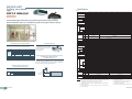
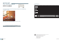
With a new colored touch panel, and continuation of all the G-50A functions, AG-150A visualizes its
functions from basic control to advanced operations and bringing an ultimate controller to reality.
Centralized controller AG-150A
New Design
System structure
Backlight color liquid crystal
Backlight makes it easy to see and control units.
One can identify whether a unit is ON or OFF from a
distance.
Control in the night with no lights is possible.
M-NET
Switching Hub
M-NET
adapter
LAN
(100BASE-TX)
M-NET
Remote
Monitoring PC
A Control
AG-150A
Touch panel
Remote monitoring
via a Web browser
Power supply unit
(PAC-SC51KUA)
9 inch wide, high-resolution
General Equipment
DIDO Controller (PAC-YG66DCA)
Switching Hub
Temp/Humidity sensor
Dimensions: 300(W) x 185(H) x 70.3(D) mm
: 11-13/16(W) x 7-5/16(H) x 2-13/16(D) in.
AI Controller (PAC-YG63MCA)
Lights
Ventilation
Watt hour meter
PI Controller (PAC-YG60MCA)
M-NET
Switching Hub
Central Control PC
(TG-2000A)
*Ver. 6.30 or later
AG-150A / GB-50ADA
VPN Modem
Router
Option : Black surface cover
PAC-YG71CBL
New Functions
Internet
Flat back
Easy installation
Service company
/Sales office
Modem
VPN
Router
Mobile phone
of service person
Touch panel enables operation of units by touching with
index finger.
When object unit is touched, orange box appears around
the unit icon indicating the unit selected.
Remote
monitoring PC
Remote monitoring
via a Web browser
Note : Use a security device such as a VPN router when connecting the
AG-150A/GB-50ADA to the Internet to prevent unauthorized access.
Allows for an installation of the unit either directly to the
wall surface* or using the installation hole in the wall.
*Optional parts are required.
USB memory compatible
Measurement/initial setting CSV data extractable with
USB memory.
Can save and overwrite setting data.
Expansion Controller PAC-YG50ECA
Functions
With a connection of a Expansion Controller, maximum of 150 units/groups
can be connected to AG-150A.
Controllable units/groups
Controls up to 50 units/groups (including indoor units,
LOSSNAY, DIDO/AI/PI controller)
Up to 150 units can be controlled via expansion
controller;PAC-YG50ECA (AG-150A software needs to be
upgraded to Ver. 2.10 or later.)
Monitoring functions
Temperature/Humidity (using AI controller with Web
browser) *1
General equipment such as lights on LCD (using DIDO
controller)
Interlock function from AI controller, DIDO controller to
indoor units and between DIDO units are available.
AG-150A interlock with DIDO controller or free contact on
an indoor unit available. * Ver. 2.30 or later
Energy saving functions
Seasonal scheduling and automatic switch over *1
Yearly scheduling on LCD *1
Scheduling fan speed and airflow direction
Optimized Start up
External temperature interlock control
Night setback control
*1 License required.
50 units/groups or 150 units/groups via expansion controller; PAC-YG50ECA.
System structure
Power supply unit
(PAC-SC51KUA)
Dimensions: 250(W) x 217(H) x 97.2(D) mm
: 9-7/8(W) x 8-9/16(H) x 3-7/8(D) in.
LAN
(100BASE-TX)
PAC-YG50ECA
Auto mode is for CITY MULTI R2 and WR2 series only.
Cool/Dry : 19˚C-30˚C (14˚C-30˚C) / 67˚F-87˚F(57˚F-87˚F)
Heat
: 17˚C-28˚C (17˚C-28˚C) / 63˚F-83˚F(63˚F-83˚F)
Auto
: 19˚C-28˚C (17˚C-28˚C) / 63˚F-83˚F(63˚F-83˚F)
AG-150A
PAC-YG50ECA
Central Control PC
(TG-2000A)
PAC-YG50ECA
*Do not connect PAC-YG50ECA to TB3 of the outdoor unit.
*Use a security device such as a VPN router when connecting the AG-150A etc. to the Internet
to prevent unauthorized access.
♦Future release schedule is subject to change without notice.
Remote Controller
Page 23
Remote Controller
Page 24
Centralized
Remote Controller
Centralized controller GB-50ADA-J*
*GB-50ADA-J is indicated as GB-50ADA.
New
The Web Server Function enables Remote Operation or Scheduling
Via a Web Browser on a Personal Computer!
Up to 50 indoor units can be controlled!
Web Browser
Enables monitoring and operation of indoor units using a PC
with Microsoft® Internet Explorer (Ver.6 or 7 or 8) (Web browser
function is an optional and needs license registration.)
GB-50ADA (without display)
• Dimensions:250 (W) x 217 (H) x 97.2 (D) mm
:9-7/8 (W) x 8-9/16 (H) x 3-7/8 (D) in.
PI Controller PAC-YG60MCA
*When connecting to the Internet, please use the VPN (Virtual Private
Network).
No more PLCs are needed!
Our new PI controller makes it possible to perform energy
saving without PLC, which is cost saving.
Maximum of 4 measurement meter (WHM, gas meter, water
meter, calorie meter) can be connected to the PI controller
and can be used also for charge calculation.
Using “Dial-up Connection”
• Enables monitoring and operation from a remote place
• Enables error notification by e-mails to a PC or to a mobile phone
Description
Function
GB-50ADA (web browser)
Dimension: 200(W) x 120(H) x 45(D) mm
: 7-7/8(W) x 4-3/4(H) x 1-13/16(D) in.
Up to 50 units/groups.
250 (9-7/8) x 217 (8-9/16) x 97.2 (3-7/8) mm (in)
Run and stop operation for the air conditioner units
Switches between Cool / Dry / Auto / Fan / Heat.
The temperature can be set within the following range.
Cool/Dry :19°C-30°C (14°C-30°C) / 67°F-87°F (57°F-87°F)
Heat
:17°C-28°C (17°C-28°C) / 63°F-83°F (63°F-83°F)
Auto
:19°C-28°C (17°C-28°C) / 67°F-83°F (63°F-83°F)
Controllable unit
Dimensions W x H x D
ON / OFF
Mode selection
Temperature setting
Energy Saving Control (Peak Cut)
( ) in case of using middle-temperature on PEFY, PEFY-VML/VMR/VMS/VMH by setting DipSW7-1 to ON. Yet, PEFY-P-VMH-E-F is excluded.
Air flow direction setting
Timer operation / Schedule
Permit / Prohibit function
Indoor unit intake temperature
Error
Test run
Ventilation interlock
*Set temperature range varies depending on the model.
Air flow direction angles, 4-angle or 5-angle Swing, Auto (Louver cannot be set)
Annaul/Weekly (2 types)/today schedule can be set for each group of air conditioning units.
Optimized startup setting is also available.
Individually prohibit operation of each local remote control function
Measures the intake temperature of the indoor unit only when the indoor unit is operating.
When an error is currently occurring on an air conditioner unit, the afflicted unit and the error code are displayed.
Operation of indoor groups or general equipment can be interlocked by the change of state (ON/OFF, mode, error of indoor groups
and general equipment).
*NOTE: Operation and displayed content vary depending on the indoor unit model.
License registration is necessary to perform each function on GB-50ADA.
System Structure
Remote monitoring via a
Switching
Web browser
LAN Hub
*24 VDC power needs to be provided on site.
Enables Energy Saving Control with the use of our new PI controller.
(Registration of “Energy Management license pack” is required.)
80%
To perform energy saving, the capacity of the outdoor unit is
controlled.
Maximum Capacity at 80%
Amount of saved energy
Capacity
Value
No energy-saving With energy-savining effects
effects
Time
*Please note that when using an energy saving control,
there are no warranties to failures such as usage over the contracted electricity.
System Structure
Remote monitoring via a
Web browser
GB-50ADA
. Control level setting
. Monitors current state
AG-150A
LAN
M-NET
Capacity
. Monitors demand level
Web license
M-NET
Registration of
“Energy Management
license pack”
. Outdoor unit control
- Capacity control
. Indoor unit control
- ± 2°C control
- Fan control
- Stop control
. Monitors electric power
Example of display icons (air conditioner icons)
Router
Error mail
Provider
PI controller
Transmits abnormality mail.
Watt-hour meter
Max. 4
Public telephone line
Note : Use a security device such as a VPN router when connecting the
AG-150A/GB-50ADA to the Internet to prevent unauthorized access.
Charge Calculation
Annual / Weekly Schedule
Enables charge calculation for each tenant and output as CSV file
Enables Weekly and Annual scheduling with a registering
license
System Structure
• ON/OFF, operation mode, temperature setting, prohibit remote
controller operation can be set.
• For annual schedule, it is possible to set 50 day-long settings up to
24 months into the future.
TG-2000A collects operation
and electric power data from
AG-150A and PI controller and
does apportion calculation.
Scheduling example in the office
8:00
(Start)
12:00
13:00
15:00
(Lunchtime)
(Energy saving)
ON
17:00
27°C [81°F] Cooling
OFF
1 All operations
permitted
2 All operations
prohibited
3 Temperature
adjustment
prohibited
(Overtime)
29°C [84°F] Cooling
4 All operations
permitted
5 Temperature
adjustment
prohibited
Up to 12 operation settings per day in 1-minute increment
Remote Controller
Page 25
LAN
22:00
AG-150A monitors every minute and
stores operation data necessary for
charging.
AG-150A
M-NET
Registration of
“Energy Management
license pack”
6 All operations
prohibited
PI controller counts pulse output from
the watt-hour meter.
PI controller
Watt-hour meter
Remote Controller
Page 26
Centralized
Remote Controller
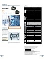
DIDO Controller PAC-YG66DCA
Integrated centralized control software TG-2000A
No more PLCs are needed!
Our new DIDO controller makes it possible to control
general-purpose equipment without PLC, which is cost saving.
Up to 6 general-purpose equipment can be connected to
the DIDO controller.
*24 VDC power needs to be provided on site.
Input
AG-150A
Single-phase 208/230V
Enables to control and monitor equipment other than air-conditioners (air-conditioners of other companies,
lights, ventilators, etc.)
System Structure
Power supply unit
PAC-SC51KUA
Indoor unit system watt-hour meter
• In addition to above, the
air-conditioners can be interlocked
with general-purpose equipment.
E.g. Interlock between indoor units
and security system.
• The indoor units can be turned
ON/OFF when the security system
is activated/deactivated.
3-phase 208/230V
(3-wire)
AG-150A
LAN
M-NET
This device complies with Part15 of the FCC Rules.Operation is
subject to the following two conditions: (1)this device may not cause
harmful interference, and (2)this device must accept any interference
received, including interference that may cause undesired operation.
[ 24 VDC Power Supply]
PI Controller
(PAC-YG60MCA)
Indoor unit system watt-hour meter
PLC (PAC-YG21CDA)
Outdoor unit system
watt-hour meter
The electric amount count software or separately
procured parts must be used with the designated PLC.
power source
Indoor unit system watt-hour meter
Uninterruptive
power supply (UPS)
DIDO controller
Icon display (Lights)
Lights
Security card reader
Error
Energy
management
license
pack
M-NET
24VDC
General-purpose equipment Control
OFF
Single-phase 208/230V
*1
etc.
Dimension: 200(W) x 120(H) x 45(D) mm
: 7-7/8(W) x 4-3/4(H) x 1-13/16(D) in.
ON
Example of Basic System Configuration
Personal computer for
TG-2000A
Indoor unit watt-hour meter
Outdoor unit system watt-hour meter
PLC (with electric amount count software)
AC of other companies
Schedule set
Integrated
centralized control
software installation
AI Controller PAC-YG63MCA
Our new AI controller makes it possible to monitor the values
measured by the temperature/humidity sensor connected to
the AI controller.
The AI controller has two input and two output channels.
*1 GB-50ADA can be used.
*24 VDC power needs to be provided on site.
The air-conditioning layout can be displayed
on the screen, making control and operation
easier.
Temperature/Humidity Monitoring
Monitors the values measured by the temperature/humidity
Dimension: 200(W) x 120(H) x 45(D) mm
: 7-7/8(W) x 4-3/4(H) x 1-13/16(D) in. sensor connected to the AI controller
Temperature : Pt100, 4 to 20mA DC, 1 to 5 VDC, 0 to 10 VDC
Humidity : 4 to 20mA DC, 1 to 5 VDC, 0 to 10 VDC
• Trend displays of measurement data can be shown on a Web browser.
• An alarm can be output by e-mail when measurement data exceeds a preset upper or lower limit.
System Structure
Effective use of TG-2000A
Remote monitoring via a
Web browser
Multiple air conditioning charges in multiple buildings can be calculated. The power apportionment percentage
data and apportioned power rate can be calculated for each unit, and can be output as a CSV file.
AG-150A
LAN
M-NET
For example, installing TG-2000A to the system in the headquarters makes it possible to control AG-150A/GB-50ADA
units that are used in branch offices.
Temperature sensor
AI controller
Remote Controller
Page 27
Humidity sensor
Remote Controller
Page 28
LONWORKS (LMAP02)
BACnet® (BAC-HD150)
CITY MULTI can easily combine into a Building Management System (BMS) via the LONWORKS and M-NET adapter LMAP02.
LONWORKS is an opened transmission protocol widely used at BMS, and related equipment control.
CITY MULTI is therefore compatible with large-scaled BMS management via LONWORKS .
CITY MULTI can easily combine into a Building Management System (BMS) via the BACnet® and M-NET adapter BAC-HD150. BACnet
is an opened transmission protocol widely used at BMS, and related equipment control. CITY MULTI is therefore compatible with
large-scaled BMS management via BACnet.
One LM ADAPTER unit can connect up to 50 Groups/50 indoor units.
Using a single LONWORKS adapter (LM ADAPTER), you can connect up to a maximum of 50 indoor units.
BAC-HD150 can control up to 50 units/groups (including LOSSNAY).
Up to 150 units/groups (including LOSSNAY) can be controlled from one BAC-HD150 with three expansion controllers
PAC-YG50ECA. (50 units/PAC-YG50ECA)
LMAP
LMAP 02
Protocol converter
between LONWORKS
and M-NET
LONWORKS
M-NET
LMAP
System example (Connection of 150 units / groups with PAC-YG50ECA)
CITY MULTI System
Central
monitor
BACnet® /IP
Example of System Configuration
BACnet® /IP
CITY MULTI
System design made simple through integration of
various devices into a total control configuration.
BMS
LAN1
LAN2
M-NET
M-NET
Outdoor unit
Outdoor unit
BAC-HD150
PAC-YG50ECA
HUB
ME remote
controller
PAC-SC51KUA
LONWORKS
(78kbps)
M-NET
LAN
ME remote
controller
M-NET
LMAP
LOSSNAY unit
ME remote
controller
PZ-52SF
AG-150A
Indoor units
Max. 50 indoor units
Indoor units
Indoor units
Indoor units
Indoor units
M-NET
M-NET
M-NET
PAC-YG50ECA
Lighting
Center
control device
Remote
controller
Security
Remote
controller
Remote
controller
Remote
controller
Remote
controller
ME remote
controller
M-NET
M-NET
LON, LONWORKS and the Echelon logo are trademarks of Echelon Corporation registered in the United
States and other countries.
INTERFACE
FUNCTION
Control
ON/OFF
Mode Operation
Setpoint Adjustment
Fan Speed Control
Permit/Prohibit
Emergency Stop
Monitoring
ON/OFF
Mode
Setpoint
Fan Speed
Permit/Prohibit
Alarm State
Room Temperature
Thermo ON/OFF
Remote Controller
Page 29
CONTENT
Run/Stop
Cooling/Drying/Heating/Auto/Fan
Cooling 19-30°C,Heating 17-28°C,Auto 19-28°C
Lo-Mi1-Mi2-Hi
On/Off,Mode,Setpoint
Run/Stop
Cooling/Drying/Heating/Auto/Fan
Cooling 19-30°C,Heating 17-28°C,Auto 19-28°C
Lo-Mi1-Mi2-Hi
On/Off,Mode,Setpoint
-10°C~50°C
On/Off
LOSSNAY unit
PAC-YG50ECA
LONWORKS
The building management system is connected to the CITY MULTI air conditioning system using LONWORKS , which is widely used on field
networks, allowing for an open network and savings in construction to face.
LONWORKS
ME remote
controller
ME remote
controller
PZ-52SF
BACnet® and M-NET adapter
FUNCTION
Operation
ON/OFF
Mode
Fan Speed
Airflow Direction
Set Temperature
Filter Sign Reset
Permit/Prohibit
Forced OFF
Monitoring
ON/OFF
Mode
Fan Speed
Air Direction
Set Temperature
Filter Sign
Permit/Prohibit
Indoor Temperature
Alarm Signal
Error Code
Communication State
CONTENT
Run/Stop
Cool/Dry/Heat/Auto/Fan
Low-Mid1-Mid2-Hi
Horizontal- 60°-80°-100°swing
Cooling 19-30°C [67-87°F], Heating 17-28°C [63-83°F], Auto 19-28°C [67-83°F]
Normal/Reset
ON/OFF, Mode, Filter sign reset, Set temp.
Release/Effective
Run/Stop
Cool/Dry/Heat/Auto/Fan
Low-Mid1-Mid2-Hi
Horizontal- 60°-80°-100°swing
Cooling 19-30°C [67-87°F], Heating 17-28°C [63-83°F], Auto 19-28°C [67-83°F]
Normal/Reset
ON/OFF, Mode, Filter sign reset, Set temp.
Normal/Abnormal
2 Character code- Indicates all unit alarms
Normal/Abnormal
Remote Controller
Page 30
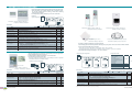
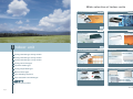
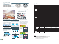
Wide selection of indoor units
Ceiling cassette (4-way air flow)
Page33
- Page34
Fresh Air Intake
Page47
PLFY-P VBM-E
PLFY-P VCM-E
Model
P20
P25
P32
P40
P50
Capacity
2.2kW
2.8kW
3.6kW
4.5kW
5.6kW
PEFY-P VMH-E-F
Model
P63
P80
P100
P125
Model
P80
P140
P200
P250
Capacity
7.1kW
9.0kW
11.2kW
14.0kW
Capacity
9.0kW
16.0kW
22.4kW
28.0kW
Ceiling cassette (2-way air flow)
Page35
- Page36
Ceiling suspended
Page49
PLFY-P VLMD-E
I ndoor unit
Model
P20
P25
P32
P40
P50
Capacity
2.2kW
2.8kW
3.6kW
4.5kW
5.6kW
Model
P63
P80
P100
P125
Model
P40
P63
P100
P125
Capacity
7.1kW
9.0kW
11.2kW
14.0kW
Capacity
4.5kW
7.1kW
11.2kW
14.0kW
Page37
- Page38
Wall mounted
Page51
PMFY-P VBM-E
PKFY-P VKM-E
Ceiling cassette type 2-way airflow
Ceiling cassette type 1-way airflow
Ceiling suspended type
- Page52
PKFY-P VBM-E
Ceiling cassette type 4-way airflow
Fresh Air Intake type
- Page50
PCFY-P VKM-E
Ceiling cassette (1-way air flow)
Ceiling concealed type
- Page48
PKFY-P VHM-E
Model
P20
P25
P32
P40
Model
P15
P20
P25
Capacity
2.2kW
2.8kW
3.6kW
4.5kW
Capacity
1.7kW
2.2kW
2.8kW
Ceiling concealed
Page39
- Page46
P40
P50
3.6kW 4.5kW
P32
5.6kW
Floor standing / Floor mounted concealed
P63
P100
7.1kW 11.2kW
Page53
- Page58
Wall mounted type
PEFY-P VMR-E-L/R
Floor standing exposed
PEFY-P VMA(L)-E
PFFY-P VLEM-E
New
PFFY-P VKM-E
Floor mounted concealed type
PEFY-P VMS1(L)-E
OA Processing Units
PEFY-P VMH(S)-E
Model
P15
P20
P25
P32
P40
P50
P63
Capacity
1.7kW
2.2kW
2.8kW
3.6kW
4.5kW
5.6kW
7.1kW
P125
P140
P200
P250
Model
P71
P80
P100
Capacity
8.0kW
9.0kW
11.2kW
14.0kW 16.0kW
22.4kW 28.0kW
PFFY-P VLRM-E
PFFY-P VLRMM-E
Model
P20
P25
P32
P40
P50
P63
Capacity
2.2kW
2.8kW
3.6kW
4.5kW
5.6kW
7.1kW
Indoor Unit
Page 31
Page 32
INDOOR UNIT
Ceiling cassette type
4-way airflow
PLFY-P VBM-E
PLFY-P VCM-E
Specifications
Power source
*1
*1
*1
Heating capacity
*1
Cooling
Power
Heating
consumption
Cooling
Current
Heating
External finish Unit
(Munsell No.)
Panel
Dimension
Unit
HxWxD
Panel
Unit
Net weight
Panel
Heat exchanger
Type x Quantity
*2
Airflow rate
Fan
(Lo-Mid1-Mid2-Hi)
Cooling capacity
PLFY-P VBM
PLFY-P VCM
The new 4-way cassette VBM offers 72 different airflow patterns, making
it ideal for applications with ceilings up to 4.2 m (13-13/16ft) in height.
Compact body to match with 2 feets
(600mm) x 2 feets (600mm) ceiling
design (VCM)
570mm
570mm
Motor
External static pressure
Type
Output
kW
BTU/h
kW
BTU/h
kW
kW
A
A
mm(in.)
mm(in.)
kg(lbs.)
kg(lbs.)
m3/min
L/s
cfm
Pa
PLFY-P32VBM-E PLFY-P40VBM-E PLFY-P50VBM-E PLFY-P63VBM-E PLFY-P80VBM-E PLFY-P100VBM-E PLFY-P125VBM-E
1-phase 220-240V 50Hz / 1-phase 220V 60Hz
3.6
4.5
9.0
5.6
7.1
11.2
14.0
12,300
15,400
30,700
19,100
24,200
38,200
47,800
4.0
5.0
10.0
6.3
8.0
12.5
16.0
13,600
17,100
34,100
21,500
27,300
42,700
54,600
0.04
0.03
0.07
0.05
0.15
0.16
0.03
0.02
0.06
0.04
0.14
0.15
0.29
0.22
0.51
0.36
1.00
1.07
0.22
0.14
0.43
0.29
0.94
1.00
Galvanized steel sheet
White (6.4Y 8.9/0.4)
298 x 840 x 840 (11-3/4 x 33-1/8 x 33-1/8)
258 x 840 x 840 (10-3/16 x 33-8/1 x 33-8/1)
35 x 950 x 950 (1-3/8 x 37-7/16 x 37-7/16)
27 (60)
22 (49)
23 (51)
6 (13)
Cross fin (Aluminum plate fin and copper tube)
Turbo fan x 1
14-15-16-18
11-12-13-14
12-13-14-16
183-200-217-233
388-424-459-494
200-217-233-267
424-459-494-565
22-25-28-30
21-24-27-29
16-18-20-22
233-250-267-300 267-300-333-367 350-400-450-483 367-417-467-500
494-530-565-636 565-636-706-777 742-848-953-1024 777-883-989-1059
0
DC motor
0.120
PP Honeycomb
0.050
kW
Air filter
Refrigerant
pipe diameter
Automatic Air Speed Adjustment
Auto-fan-speed mode enables speedy and
comfortable heating during heating startup.
The Auto-fan-speed mode is added to the
usual four steps “Low, Mid1, Mid2, High.”
The Auto-fan-speed mode enables speedy
and comfortable air conditioning because the
air flow speeds up when starting, and air flow
slows down when the air conditioning
becomes stable. (PLFY-P VBM-E ONLY)
Controls the four fan speed modes automatically
Low
Mid1
Mid2
High
Auto
* When using a wireless remote controller, initial settings are
required.
Draft-less Air Distribution
The horizontal blow mode* newly employed
supplies airflow horizontally not bringing
cooled/warmed air directly to occupants thus
preventing discomfort sensation due to
excessive cooling or direct exposing of
occupants to the air blow.
(PLFY-P VBM-E ONLY)
Wide Air Flow
(PLFY-P VBM-E ONLY)
Cooling softly with Wide Air Flow
Discharge air reaches wider area and the fan
speed is decreased by 20% thanks to the new
wide shape air outlet.
Conventional model
New model
“i-see sensor” can be used with
ceiling cassette type 4-way airflow
unit. (Option PAC-SA1ME-E, PLFYVBM-E ONLY)
New 4-way Cassette PLFY-VBM controls the
temperature difference at the top and bottom in
a room by checking the floor temperature with
“i-see sensor”. Comfortable air conditioning can
be realized smoothly with “sensible temperature
control.” (Option PAC-SA1ME-E, PLFY-VBM-E
ONLY)
Prevents overcooling/overheating, and
improves comfort/energy-efficiency
First in the industry
72 patterns of airflow to accommodate*On the commercial air
conditioners (According to the
any room layout are available.
survey by Mitsubishi Electric)
The number of outlet can be set to 4, 3, or 2. Flexible airflow is
available by fixing the up-down airflow direction of the outlet
with a wired remote controller (or manually).
72 airflow patterns
4-, 3-, or 2- way outlet selection*
Without i-see sensor: preset temperature at 23°C
37°C
In heating
25°C
ø12.7 (ø1/2)
ø12.7 (ø1/2) / ø15.88 (ø5/8)
(Compatible)
Liquid
(Flare) mm(in.)
ø6.35 (ø1/4)
ø6.35 (ø1/4) / ø9.52 (ø3/8)
(Compatible)
Field drain pipe diameter
Sound pressure level
(Lo-Mid1-Mid2-Hi) *2 *3
27-28-29-31
27-28-30-31
PLFY-P20VCM-E
kW
*1
*1
BTU/h
kW
*1
Heating capacity
*1
BTU/h
kW
Cooling
Power
consumption
kW
Heating
A
Cooling
Current
A
Heating
External finish Unit
(Munsell No.) Panel
mm(in.)
Unit
Dimension
Panel mm(in.)
HxWxD
kg(lbs.)
Unit
Net weight
kg(lbs.)
Panel
Heat exchanger
Cooling capacity
Fan
Airflow rate * 2
(Lo-Mid-Hi)
The area that the ceiling
cassette without
“i-see sensor” can monitor.
External static
pressure
Motor
Type
Output
2.2
7,500
2.5
8,500
0.05
0.05
0.23
0.23
30-32-35-37
34-37-39-41
35-38-41-43
PLFY-P40VCM-E
4.5
15,400
5.0
17,100
0.06
0.06
0.28
0.28
208 x 570 x 570 (8-1/4 x 22-1/2 x 22-1/2)
20 x 650 x 650 (13/16 x 25-5/8 x 25-5/8)
15.5 (35)
3 (7)
17 (38)
3 (7)
Cross fin (Aluminum plate fin and copper tube)
Turbo fan x 1
m3/min
8-9-10
8-9-10
8-9-11
8-9-11
L/s
cfm
133-150-167
283-318-353
133-150-167
283-318-353
133-150-183
283-318-388
133-150-183
283-318-388
Pa
0 (direct blow)
1-phase induction motor
kW
0.011
Gas(Flare) mm(in.)
Liquid(Flare) mm(in.)
Field drain pipe diameter mm(in.)
Sound pressure level
dB(A)
(Lo-Mid-Hi)
*2 *3
Refrigerant
pipe diameter
With i-see sensor+Auto fan speed: preset temperature at 20°C
28-29-30-32
PLFY-P32VCM-E
1-phase 220-240V 50Hz
3.6
2.8
12,300
9,600
4.0
3,2
13,600
10,900
0.05
0.06
0.05
0.06
0.23
0.28
0.23
0.28
Galvanized steel sheet with gray heat insulation
White (6.4Y 8.9/0.4)
Air filter
* Optional parts air outlet shutter plate (PLFY-P VBM-E
ONLY) is required for 2 or 3 way outlet selection.
ø9.52 (ø3/8)
PLFY-P25VCM-E
Type x Quantity
Suction temperature sensor
Preset temperature is
tended to be higher
than we need,
because heated air
rises to the ceiling.
dB(A)
ø15.88 (ø5/8) / ø19.05 (ø3/4)
(Compatible)
ø15.88(ø5/8)
O.D. 32 (1-1/4)
mm(in.)
Power source
13°C
Feeling temperature
at 20°C (Bottom17°C)
Gas
(Flare) mm(in.)
28-31-35
0.015
0.02
PP Honeycomb (long life type)
ø12.7 (ø1/2)
ø6.35 (ø1/4)
O.D. 32 (1-1/4)
28-31-37
29-33-38
0.02
30-34-39
37°C
In heating
25°C
Draft-less air distribution
can be performed
by horizontal blow.
13°C
Setting the air direction for each
outlet with wired remote controller
Horizontal blow
*Default
*The ceiling may be smudged at a spot where the supplied
airflow is seriously disturbed.
Fixed
Remote controller setting Down blow
Suction temperature sensor
Feeling temperature
at 20°C (Bottom 20°C)
Auto-fan-speed mode of
4-way Cassette with
“i-see sensor” heats the
floor well and decreases
the temperature
difference at the top and
bottom in a room.
360°
The area that the ceiling
cassette with
“i-see sensor” can monitor.
Notes:
2.7m
11.5m
*1 Cooling/Heating capacity indicates the maximum value at operation under the following condition.
Cooling : Indoor 27°C(81°F)DB/19°C(66°F)WB,Outdoor 35°C(95°F)DB
Heating : Indoor 20°C(68°F)DB,Outdoor 7°C(45°F)DB/6°C(43°F)WB
*2 Airflow rate/Sound pressure level are in (low-middle-high) or (low-middle1-middle2-high).
*3 It is measured in anechoic room at power source 230V.
Indoor unit
Page 33
Specifications
Page 34
INDOOR UNIT
Ceiling cassette type
2-way airflow
PLFY-P VLMD-E
Specifications
PLFY-P20VLMD-E
*1
kW
*1 BTU/h
*1
kW
Heating capacity
*1 BTU/h
Power
Cooling
kW
consumption
Heating
kW
Cooling
A
Current
Heating
A
External finish Unit
(Munsell No.)
Panel
Dimension
Unit
mm (in.)
HxWxD
Panel mm (in.)
Unit
kg(lbs.)
Net weight
Panel
kg(lbs.)
Heat exchanger
Type x Quantity
Fan
Motor
Slim body - only 290mm(11-7/16in.) height
The slimline body is highly suitable for installation in narrow
ceiling spaces and for replacing obsolete air-conditioning
equipment in older buildings. The main unit is only 290mm(117/16in.) height.
Equipped with drain pump
mechanism as standard
The drain can be positioned anywhere up to 583mm(22-15/16in.)
from the ceiling's surface, providing greater freedom with long
cross-piping and allowing more versatility with piping layouts.
290mm
.)
(11-7/16in
Drain height
max. 583(22-15/16)
Main unit height - 290(11-7/16)
Ceiling surface
583
Terminal block on outside of main unit
makes wiring easier
mm (in.)
Compact unit and low noise level attained!
Fresh air directly taken in
Sound pressure level table (Standard static pressure) at 0Pa
dB(A)
Fresh air can be taken in to the main unit directly (optional
accessories needed.)
Capacity P20 P25 P32 P40 P50 P63 P80 P100 P125
Sound
High
33
36
37
39
39
42
46
pressure
Fan
Mid
30
33
34
37
36
39 42/44
Level
Speed
27
29
31
32
33
36
2.2
7,500
2.5
8,500
0.072 / 0.075
0.065 / 0.069
0.36 / 0.37
0.30 / 0.32
Cooling capacity
Slim body of 290mm(11-7/16in.) height
Low
PLFY-P25VLMD-E
PLFY-P32VLMD-E
1-phase 220-240V 50Hz / 1-phase 220-230V 60Hz
3.6
2.8
12,300
9,600
4.0
3.2
13,600
10,900
0.072 / 0.075
0.072 / 0.075
0.065 / 0.069
0.065 / 0.069
0.36 / 0.37
0.36 / 0.37
0.30 / 0.32
0.30 / 0.32
Galvanized steel plate
Pure white (6.4Y 8.9/0.4)
290 x 776 x 634 (11-7/16 x 30-9/16 x 25)
20 x 1080 x 710 (13/16 x 42-9/16 x 28)
Power source
40
Airflow rate *2
(Lo-Mid-Hi)
External static pressure
Type
Output
23 (51)
PLFY-P40VLMD-E
4.5
15,400
5.0
17,100
0.081 / 0.085
0.074 / 0.079
0.40 / 0.42
0.34 / 0.37
24 (53)
6.5 (15)
Cross fin
Turbo fan x 1
7.0-8.5-10.5
117-142-175
247-300-371
6.5-8.0-9.5
108-133-158
230-283-335
m3/min
L/s
cfm
Pa
0
1-phase induction motor
0.015 (at 240V)
PP honeycomb fabric (long life type)
ø12.7 (ø1/2)
ø6.35 (ø1/4)
O.D.32 (1-1/4)
27-30-33
28-31-34
kW
Air filter
Refrigerant
Gas(Flare) mm(in.)
pipe diameter Liquid(Flare) mm(in.)
Field drain pipe diameter mm(in.)
Sound pressure level 220V,240V dB(A)
(Lo-Mid-Hi) *2 *3 230V
dB(A)
29-33-36
30-34-37
PLFY-P50VLMD-E
Power source
*1
*1
*1
Heating capacity
*1
Cooling
Power
Heating
consumption
Cooling
Current
Heating
External finish Unit
(Munsell No.) Panel
Unit
Dimension
Panel
HxWxD
Unit
Net weight
Panel
Heat exchanger
Type x Quantity
Airflow rate *2
Fan
(P50~P100:Lo-Mid-Hi)
(P125:Lo-Mid2-Mid1-Hi)
External static pressure
Type
Motor
Output
Cooling capacity
kW
BTU/h
kW
BTU/h
kW
kW
A
A
mm (in.)
mm (in.)
kg(lbs.)
kg(lbs.)
PLFY-P63VLMD-E
PLFY-P80VLMD-E
PLFY-P100VLMD-E
1-phase 220-240V 50Hz / 1-phase 220-230V 60Hz
7.1
9.0
11.2
5.6
24,200
30,700
38,200
19,100
8.0
10.0
12.5
6.3
27,300
34,100
42,700
21,500
0.101 / 0.105
0.147 / 0.156
0.157 / 0.186
0.082 / 0.086
0.094 / 0.099
0.140 / 0.150
0.150 / 0.180
0.075 / 0.080
0.49 / 0.51
0.72 / 0.74
0.75 / 0.88
0.41 / 0.43
0.43 / 0.46
0.66 / 0.69
0.69 / 0.83
0.35 / 0.38
Galvanized steel plate
Pure white (6.4Y 8.9 / 0.4)
290 x 946 x 634 (11-7/16 x 37-1/4 x 25)
290 x 1446 x 634 (11-7/16 x 56-15/16 x 25)
20 x 1250 x 710 (13/16 x 49-1/4 x 28)
20 x 1750 x 710 (13/16 x 68-15/16 x 28)
28 (62)
44 (98)
47 (104)
27 (60)
7.5 (17)
12.5 (28)
14.0
47,800
16.0
54,600
0.28 / 0.28
0.27 / 0.27
1.35 / 1.35
1.33 / 1.33
290 x 1708 x 606 (11-7/16 x 67-1/4 x 23-7/8)
20 x 2010 x 710 (13/16 x 79-3/16 x 28)
56 (124)
13.0 (29)
Cross fin
m3/min
L/s
cfm
Pa
9.0-11.0-12.5
150-183-208
318-388-441
kW
Turbo fan x 1
11.0-13.0-15.5
167-217-258
353-459-547
0.020 (at 240V)
Air filter
Turbo fan x 2
17.5-21.0-25.0
15.5-18.5-22.0
292-350-417
258-308-367
618-742-883
547-653-777
0
1-phase induction motor
0.030 (at 240V)
0.020 (at 240V)
PP honeycomb fabric (long life type)
Refrigerant
pipe diameter
PLFY-P125VLMD-E
Gas
(Flare)
mm(in.)
ø12.7 (ø1/2)
Liquid
(Flare)
mm(in.)
ø6.35 (ø1/4)
Field drain pipe diameter mm(in.)
Sound pressure level 220V,240V dB(A)
dB(A)
(Lo-Mid-Hi) *2 *3 230V
31-34-37
32-35-38
Sirocco fan x 4
24.0-27.0-30.0-33.0
400-450-500-550
848-953-1,059-1,165
0.078 x 2 (at 240V)
Synthetic fiber unwoven
cloth filter (long life)
ø15.88 (ø5/8)
ø9.52 (ø3/8)
32-37-39
33-38-40
O.D.32 (1-1/4)
33-36-39
34-37-40
36-39-42
37-41-43
40-42-44-46
(Lo-Mid2-Mid1-Hi)
Long life filter equipped as standard
<220V,240V>
dB(A)
Capacity
Sound
High
pressure
Fan
Mid
Level
Speed
Low
<230V>
Indoor unit
Page 35
The antibacterial long life filter does not require maintenance
for approximately a year.
P20 P25 P32 P40 P50 P63 P80 P100 P125
34
37
38
40
40
43
31
34
35
38
37
41 42/44
46
28
30
32
33
34
37
40
Easy installation
Lighter panel and placing the electric board near the panel
make installation and maintenance easier. Also, the heat
exchanger is washable by displacing the center panel, filter,
and fan.
Notes:
*1
Cooling/Heating capacity indicates the maximum value at operation under the following condition.
Cooling : Indoor 27°C(81°F)DB/19°C(66°F)WB,Outdoor 35°C(95°F)DB
Heating : Indoor 20°C(68°F)DB,Outdoor 7°C(45°F)DB/6°C(43°F)WB
*2 Airflow rate/Sound pressure level are in (low-middle-high) or (low-middle2-middle1-high).
*3 It is measured in anechoic room.
Specifications
Page 36
INDOOR UNIT
Ceiling cassette type
1-way airflow
PMFY-P VBM-E
Specifications
PMFY-P20VBM-E
Power source
*1
kW
*1 BTU/h
kW
*1
Heating capacity
*1 BTU/h
Power
Cooling
kW
consumption
Heating
kW
Cooling
A
Current
Heating
A
External finish (Munsell No.)
Dimension
Unit
mm(in.)
HxWxD
Panel
mm(in.)
Unit
kg(lbs.)
Net weight
Panel
kg(lbs.)
Heat exchanger
Type
*2 m3/min
Airflow rate
Fan
L/s
(Lo-Mid2-Mid1-Hi)
cfm
External staticpressure
Pa
Type
Motor
Output
kW
Air filter
Refrigerant
Gas(Flare) mm(in.)
pipe diameter Liquid(Flare) mm(in.)
Field drain pipe diameter mm(in.)
Sound pressure level
dB(A)
(Lo-Mid2-Mid1-Hi) *2 *3
2.2
7,500
2.5
8,500
0.042
0.042
0.20
0.20
Cooling capacity
Compact and lightweight body perfect for
limited ceiling space applications.
Compact size for smooth
installation and maintenance
6.5-7.2-8.0-8.7
108-120-133-145
230-254-283-307
PMFY-P25VBM-E
PMFY-P32VBM-E
1-phase 220-240V 50Hz / 1-phase 220V 60Hz
2.8
3.6
9,600
12,300
3.2
4.0
10,900
13,600
0.044
0.044
0.21
0.21
White (0.98Y 8.99/0.63)
230 x 812 x 395 (9-1/16 x 32 x 15-9/16)
30 x 1000 x 470 (1-3/16 x 39-3/8 x 18-9/16)
14 (31)
3 (7)
Cross fin (Aluminum plate fin and copper tube)
Line flow fan x 1
7.3-8.0-8.6-9.3
122-133-143-155
258-283-304-328
0
1-phase induction motor
0.028
PP Honeycomb fabric
ø12.7 (ø1/2)
ø6.35 (ø1/4)
O.D. 26 (1)
PMFY-P40VBM-E
32-34-36-37
33-35-37-39
27-30-33-35
4.5
15,400
5.0
17,100
0.054
0.054
0.26
0.26
7.7-8.7-9.7-10.7
128-145-162-178
272-307-343-378
Drain pump
Unit body size has been standardized for all
models at 812mm for easier installation.
Body weight is only 14kg for the main unit
and 3kg for the panel, making this unit one
of the lightest in the industry.
The drain can be positioned anywhere up to 600mm(23-5/8in.) from the ceiling's surface.
max.
600
(23-5/8)
Quiet operation
Newly developed airflow control technology
reduces noise level to only 27dB (P20VBM)
for industry-leading quiet performance.
max.
402
(15-7/8)
230
(9-11/16)
PMFY-VBM
198
(7-13/16)
mm (in.)
Sound pressure level table
Capacity
P20 P25 P32 P40
35
37
39
33
36
37
Mid 2
30
34
35
Low
27
32
33
High
Sound
pressure Fan
Mid 1
level
Speed
<220V,240V>
Notes:
Indoor unit
Page 37
*1
Cooling/Heating capacity indicates the maximum value at operation under the following condition.
Cooling : Indoor 27°C(81°F)DB/19°C(66°F)WB,Outdoor 35°C(95°F)DB
Heating : Indoor 20°C(68°F)DB,Outdoor 7°C(45°F)DB/6°C(43°F)WB
*2
Airflow rate/Sound pressure level are in (low-middle2-middle1-high).
*3
It is measured in anechoic room.
Specifications
Page 38
INDOOR UNIT
Ceiling concealed type
Specifications
PEFY-P20VMR-E-L
PEFY-P VMR-E-L/R
Power source
Static Pressure
Heating capacity
5Pa
Width
640mm
25-6/32in.
Ultra
Low Noise
Cooling capacity
Piping connection
L model
R model
Power
consumption
Current
Problem solver for residential hotels, museums, libraries,
or hospitals where low noise is especially a must!
Key Card
Switch
Cooling
Heating
Cooling
Heating
kW
BTU/h
kW
BTU/h
kW
kW
A
A
2.2
7,500
2.5
8,500
0.06 / 0.06
0.06 / 0.06
0.29 / 0.29
0.29 / 0.29
External finish
Dimension Rear inlet mm (in.)
Bottom inlet mm (in.)
HxWxD
kg(lbs.)
Net weight
Heat exchanger
Type x Quantity
m3/min
Airflow rate
L/s
(Lo-Mid-Hi)
Fan
cfm
External static
Pa
*2
pressure
Type
Motor
Output
kW
Air filter
Refrigerant
mm(in.)
Gas
pipe diameter Liquid mm(in.)
Field drain pipe diameter mm(in.)
Sound pressure 220V
dB(A)
level (Lo-Mid-Hi) 230V
*3 240V
Inlet
Access
door
*1
*1
*1
*1
Noise measurement point
Noise measurement point
Operable by key card switch
It is possible to operate / stop by taking a key card in and out.
Ultra low noise
Quiet indoor environment can be achieved with 21dB around
the bed and 22dB around the desk.
*The noise level may differ by the room size or the setting of the
unit.
Enables to install for symmetric design room
Energy saving
Left or right piping and control boxes are available depending
on the layout of each room. Plus, as in the above figure, easy
maintenance is possible from the access door in the bathroom.
*Seen from the front, the pipe and control box are on the right
side for -R models.
Energy saving can be realized by preventing us from failing to
switch off of the air conditioners with a centralized system when no
one is in the room.
Note: Compact and simple controllers, designed specifically to
control only start/stop, fan speed and temperature can be set in
each room for the occupants' enhanced individual comfort.
Easy Maintenance
Heating capacity
Power
consumption
Current
Cooling
Heating
Cooling
Heating
kW
BTU/h
kW
BTU/h
kW
kW
A
A
External finish
Dimension Rear inlet mm (in.)
Bottom inlet mm (in.)
HxWxD
kg(lbs.)
Net weight
Heat exchanger
Type x Quantity
m3/min
Airflow rate
L/s
(Lo-Mid-Hi)
Fan
cfm
External static
Pa
*2
pressure
Type
Motor
Output
kW
Air filter
Refrigerant
mm(in.)
Gas
pipe diameter Liquid mm(in.)
Field drain pipe diameter mm(in.)
Sound pressure 220V
dB(A)
level (Lo-Mid-Hi) 230V
*3 240V
3.6
12,300
4.0
13,600
0.07 / 0.08
0.07 / 0.08
0.34 / 0.38
0.34 / 0.38
4.8-5.8-9.3
80-97-155
170-205-328
5
0.018
0.023
PP Honeycomb fabric (washable)
ø12.7 (ø1/2) Brazed
ø6.35 (ø1/4) Brazed
O.D. 26 (1)
20-25-33
21-26-35
22-27-33
20-25-30
21-26-32
22-27-30
PEFY-P20VMR-E-R
*1
*1
*1
*1
PEFY-P32VMR-E-L
1-phase induction motor
Power source
Cooling capacity
PEFY-P25VMR-E-L
1-phase 220-230-240V 50Hz / 1-phase 220-230V 60Hz
2.8
9,600
3.2
10,900
0.06 / 0.06
0.06 / 0.06
0.29 / 0.29
0.29 / 0.29
Galvanized
292 x 640 x 580 (11-1/2 x 25-1/4 x 22-7/8)
300 x 640 x 570 (11-7/8 x 25-1/4 x 22-1/2)
18 (40)
Cross fin (Aluminum fin and copper tube)
Sirocco fan x 1
4.8-5.8-7.9
80-97-132
170-205-279
2.2
7,500
2.5
8,500
0.06 / 0.06
0.06 / 0.06
0.29 / 0.29
0.29 / 0.29
PEFY-P25VMR-E-R
1-phase 220-230-240V 50Hz / 1-phase 220-230V 60Hz
2.8
9,600
3.2
10,900
0.06 / 0.06
0.06 / 0.06
0.29 / 0.29
0.29 / 0.29
Galvanized
292 x 640 x 580 (11-1/2 x 25-1/4 x 22-7/8)
300 x 640 x 570 (11-7/8 x 25-1/4 x 22-1/2)
18 (40)
Cross fin (Aluminum fin and copper tube)
Sirocco fan x 1
4.8-5.8-7.9
80-97-132
170-205-279
PEFY-P32VMR-E-R
3.6
12,300
4.0
13,600
0.07 / 0.08
0.07 / 0.08
0.34 / 0.38
0.34 / 0.38
4.8-5.8-9.3
80-97-155
170-205-328
5
1-phase induction motor
0.018
0.023
PP Honeycomb fabric (washable)
ø12.7 (ø1/2) Brazed
ø6.35 (ø1/4) Brazed
O.D. 26(1)
20-25-30
21-26-32
22-27-30
20-25-33
21-26-35
22-27-33
Drain pan and heat exchangers are washable from the access
door in the bathroom, making maintenance easy and cost
saving.
Notes:
*1 Cooling/Heating capacity indicates the maximum value at operation under the following condition.
Cooling : Indoor 27°C (81°F) DB/19°C (66°F) WB, Outdoor 35°C (95°F) DB
Heating : Indoor 20°C (68°F) DB, Outdoor 7°C (45°F) DB/6°C (43°F) WB
*2 The external static pressure is set to 5Pa (at 220V, 230V, 240V).
*3 Measured in anechoic room. Sound pressure levels of the unit with a rear air inlet. (Sound pressure levels are higher than the unit with a bottom air inlet.)
Indoor unit
Page 39
Specifications
Page 40
INDOOR UNIT
Ceiling concealed type
Specifications
PEFY-P VMS1(L)-E
Static Pressure
Height
5~50Pa
200mm
Power source
Width
Low Noise
7-28/32in.
*1
*1
*1
Heating capacity
*1
Power
*3 Cooling
consumption Heating
Cooling
Current *3
Heating
External finish
Dimension
HxWxD
Net weight
*3
Heat exchanger
Type x Quantity
Cooling capacity
790mm
31-1/8in.
Width
Width
990mm 1,190mm
39in.
46-7/8in.
The ultra thin unit of 200mm offers increased flexibility, and is
particularly suitable for places where low noise operation is desired
from a slim line body.
Fan
Motor
Airflow rate
(Lo-Mid-Hi)
External static press
type
output
PEFY-P15VMS1(L)-E PEFY-P20VMS1(L)-E PEFY-P25VMS1(L)-E PEFY-P32VMS1(L)-E PEFY-P40VMS1(L)-E PEFY-P50VMS1(L)-E PEFY-P63VMS1(L)-E
1-phase 220-240V 50Hz / 1-phase 220-240V 60Hz
4.5
3.6
kW
7.1
5.6
2.8
1.7
2.2
15,400
12,300
BTU/h
24,200
19,100
9,600
5,800
7,500
5.0
4.0
kW
8.0
6.3
3.2
1.9
2.5
17,100
13,600
BTU/h
27,300
21,500
10,900
6,500
8,500
0.07 [0.05]
0.07 [0.05]
kW
0.09 [0.07]
0.09 [0.07]
0.06 [0.04]
0.05 [0.03]
0.05 [0.03]
0.05 [0.05]
0.05 [0.05]
kW
0.07 [0.07]
0.07 [0.07]
0.04 [0.04]
0.03 [0.03]
0.03 [0.03]
0.56 [0.45]
0.50 [0.39]
A
0.72 [0.61]
0.67 [0.56]
0.50 [0.39]
0.42 [0.31]
0.47 [0.36]
0.45 [0.45]
0.39 [0.39]
A
0.61 [0.61]
0.56 [0.56]
0.39 [0.39]
0.31 [0.31]
0.36 [0.36]
Galvanized
200 x 790 x 700
200 x 990 x 700
200 x 1,190 x 700
mm
7-7/8 x 31-1/8 x 27-9/16
7-7/8 x 39 x 27-9/16
7-7/8 x 46-7/8 x 27-9/16
In.
24(53) [23(51)]
20(45) [19(42)]
19(42) [18(40)]
28(62) [27(60)]
kg(lbs.)
Cross fin (Aluminium fin and copper tube)
Sirocco fan x 3
Sirocco fan x 2
Sirocco fan x 4
8-9.5-11
6-8-10
9.5-11-13
5.5-7-9
5.5-6.5-8
5-6-7
12-14-16.5
m3/min
100-133-167
133-158-183
158-183-217
91-117-150
91-108-133
83-100-117
200-233-275
L/s
212-282-353
282-335-388
335-388-459
194-247-317
194-229-282
176-212-247
424-494-583
cfm
5-15-35-50
Pa
DC motor
0.096
kW
PP Honeycomb fabric (washable)
ø15.88 (ø5/8) Brazed
mm(in.)
ø12.7 (ø1/2) Brazed
ø9.52 (ø3/8) Brazed
mm(in.)
ø6.35 (ø1/4) Brazed
O.D. 32 (1-1/4)
mm(in.)
Air filter
Refrigerant Gas
pipe diameter Liquid
Field drain pipe diameter
Sound pressure level
(Lo-Mid-Hi)
dB<A>
(mesured in anechoic room)
Changeable static pressure
The unit is made suitable for a variety of applications with its four static pressure settings of 5, 15,
35, 50Pa.
22-24-28
23-25-29
24-26-30
24-27-32
28-30-33
30-32-35
30-33-36
Ultra low height unit with 200mm (7-28/32in.) high
Ultra-narrow width of 790mm (P15-P32 models)
[990mm for P40,50 models / 1190mm for P63 models]
Can be installed easily in tight spaces, such as ceiling cavities or drop-ceilings.
790mm
Choice for drain pump
Drain pump is an optional part for the VMS1L, and
a standard for VMS1.
*For places where low noise operation is especially
required (i.e. Hotels), VMS1L (without drain pump)
is recommended.
Ceiling surface
200mm
More than 10mm
Low, middle, and high fan speed settings deliver
precise comfort.
More than 20mm
Changeable airflow rate
Access door
Make the access door at the appointed position properly
for service maintenance.
Reduced noise thanks to the use of newly
designed centrifugal fan and coil
Sound pressure level table (Standard static pressure) at 15Pa
dB(A)
PP Honeycomb fabric
Washable PP Honeycomb fabric filter as standard
Capacity
P15
P20
P25
P32
P40
P50
P63
Sound
High
pressure
Fan
Level Speed Mid
28
29
30
32
33
35
36
24
25
26
27
30
32
33
Low
22
23
24
24
28
30
30
Notes:
*1 Cooling/Heating capacity indicates the maximum value at operation under the following condition.
Cooling : Indoor : 27°CD.B./19°CW.B. (81°FD.B. / 66°FW.B.) Outdoor : 35°CD.B. (95°FD.B. )
Heating : Indoor : 20°CD.B. (68°FD.B.) Outdoor : 7°CD.B. / 6°CW.B. (45°FD.B. / 43°FW.B.)
Pipe length : 7.5m (24-9/16ft)
Height difference : 0m (0ft)
*2 The external static pressure is set to 15 Pa at factory shipment.
*3 [
Indoor unit
Page 41
] is in case of PEFY-P15-63VMS1L-E
Specifications
Page 42
INDOOR UNIT
Ceiling Concealed Type
Specifications
PEFY-P20VMA(L)-E
PEFY-P VMA(L)-E
Middle Static Pressure
Power source
Cooling capacity
(Nominal)
Heating capacity
(Nominal)
Power
Cooling
consumption Heating
Cooling
Current
Heating
External finish
Slim Body
35~150Pa Height 250mm
With precise control of indoor temperature while operating with
optimum energy usage, it offers a high-energy saving efficiency.
Dimension H x W x D
Net weight
Heat exchanger
Type x Quantity
Air Inlet
(1) Rear inlet
(2) Bottom inlet
Fan
Air inlet
Motor
Air inlet
Air outlet
*1
*1
*2
*2
*3
*3
*3
*3
Air outlet
* The units with bottom inlet make more noise than those with rear inlet.
It is recommended that the rear inlet be selected when installing the units in the
rooms that should be quiet such as bedrooms.
Compact Indoor Units
Drain Pump Option
For all models, unit height are unified to 250mm. Compared to the
previous model, the height size is reduced, allowing installation in
tight spaces, such as ceiling cavities or drop-ceilings.
The line-up consists of two types, models with or without a
built-in drain pump allowing more freedom in piping layout
design.
Airflow rate
(Low-Mid-High)
External static
pressure
*4
Type
Output
Power source
Cooling capacity
(Nominal)
Heating capacity
(Nominal)
Power
Cooling
consumption Heating
Cooling
Current
Heating
External finish
*1
*1
*2
*2
*3
*3
*3
*3
Net weight
Heat exchanger
Type x Quantity
Fan
PEFY-P VMA-E Drain pump built-in
Reduction in height size
Motor
PEFY-P VMA(L)
Height mm
Width mm
Depth mm
20
25
700
32
40
50
900
63 71 80 100 125 140
250
1,100
1,400 1,600
732
PEFY-P VMAL-E No Drain pump
2.2
7,500
2.5
8,500
0.06 [0.04]
0.04
0.53 [0.42]
0.42
mm
in.
kg(lbs)
250 x 700 x 732
9-7/8 x 27-9/16 x 28-7/8
23 (51) [22 (49)]
m3/min
L/s
cfm
6.0 - 7.5 - 8.5
100 - 125 - 142
212 - 265 - 300
kW
Airflow rate
(Low-Mid-High)
External static
pressure
*4
Type
Output
250 x 900 x 732
9-7/8 x 35-7/16 x 28-7/8
26 (58) [25 (56)]
12.0 - 14.5 - 17.0
200 - 242 - 283
424 - 512 - 600
0.085
0.085
6.35 (1/4) Brazed
12.7 (1/2) Brazed
O.D.32(1-1/4)
6.35 (1/4) Brazed
12.7 (1/2) Brazed
O.D.32 (1-1/4)
6.35 (1/4) Brazed
12.7 (1/2) Brazed
O.D.32 (1-1/4)
26-28-29
23-25-26
28-30-34
23-26-29
28-30-34
23-27-30
28-32-35
25-29-32
0.085
PEFY-P71VMA(L)-E
kW
BTU/h
kW
BTU/h
kW
kW
A
A
7.1
24,200
8.0
27,300
0.12 [0.10]
0.10
1.01 [0.90]
0.90
8.0
27,300
9.0
30,700
0.14 [0.12]
0.12
1.15 [1.04]
1.04
mm
in.
kg(lbs)
250 x 1,100 x 732
9-7/8 x 43-5/16 x 28-7/8
32 (71) [31(69)]
250 x 1,100 x 732
9-7/8 x 43-5/16 x 28-7/8
32 (71) [31 (69)]
m3/min
L/s
cfm
13.5 - 16.0 - 19.0
225 - 267 - 317
477 - 565 - 671
14.5 - 18.0 - 21.0
242 - 300 - 350
512 - 636 - 742
kW
5.6
19,100
6.3
21,500
0.11 [0.09]
0.09
0.74 [0.63]
0.63
DC motor
0.085
PP honeycomb fabric.
6.35 (1/4) Brazed
12.7 (1/2) Brazed
O.D.32(1-1/4)
0.085
PEFY-P63VMA(L)-E
Pa
PEFY-P50VMA(L)-E
<20> - <35> - 50 - <70> - <100> - <150> <20> - <35> - 50 - <70> - <100> - <150> <20> - <35> - 50 - <70> - <100> - <150> <20> - <35> - 50 - <70> - <100> - <150> <20> - <35> - 50 - <70> - <100> - <150>
Air filter
Refrigerant
6.35 (1/4) Brazed
Liquid (R410A) mm(in.)
pipe diameter Gas (R410A) mm(in.)
12.7 (1/2) Brazed
Field drain pipe diameter mm(in.)
O.D.32 (1-1/4)
Sound pressure level (measured in anechoic room)
(Low-Mid-High) *3 *5 dB(A)
26-28-29
23-25-26
*3 *6 dB(A)
Dimension H x W x D
250mm
kW
BTU/h
kW
BTU/h
kW
kW
A
A
Pa
PEFY-P40VMA(L)-E
PEFY-P32VMA(L)-E
1-phase 220-230-240V 50 / 60Hz
4.5
3.6
2.8
15,400
12,300
9,600
5.0
4.0
3.2
17,100
13,600
10,900
0.09 [0.07]
0.07 [0.05]
0.06 [0.04]
0.07
0.05
0.04
0.64 [0.53]
0.55 [0.44]
0.53 [0.42]
0.53
0.44
0.42
Galvanized steel plate
250 x 700 x 732
250 x 900 x 732
250 x 700 x 732
9-7/8 x 27-9/16 x 28-7/8 9-7/8 x 35-7/16 x 28-7/8
9-7/8 x 27-9/16 x 28-7/8
23 (51) [22 (49)]
26 (58) [25 (56)]
23 (51) [22 (49)]
Cross fin (Aluminum fin and copper tube)
Sirocco fan x 1
7.5 - 9.0 - 10.5
10.0 - 12.0 - 14.0
6.0 - 7.5 - 8.5
125 - 150 - 175
167 - 200 - 233
100 - 125 - 142
265 - 318 - 371
353 - 424 - 494
212 - 265 - 300
PEFY-P25VMA(L)-E
PEFY-P80VMA(L)-E PEFY-P100VMA(L)-E PEFY-P125VMA(L)-E PEFY-P140VMA(L)-E
1-phase 220-230-240V 50 / 60Hz
9.0
11.2
14.0
16.0
47,800
30,700
38,200
54,600
16.0
10.0
12.5
18.0
54,600
34,100
42,700
61,400
0.34 [0.32]
0.14 [0.12]
0.24 [0.22]
0.36 [0.34]
0.32
0.12
0.22
0.34
2.05 [1.94]
1.15 [1.04]
1.47 [1.36]
2.21 [2.10]
1.94
1.04
1.36
2.10
Galvanized steel plate
250 x 1,100 x 732
250 x 1,400 x 732
250 x 1,400 x 732
250 x 1,600 x 732
9-7/8 x 43-5/16 x 28-7/8 9-7/8 x 55-1/8 x 28-7/8
9-7/8 x 55-1/8 x 28-7/8
9-7/8 x 63 x 28-7/8
32 (71) [31 (69)]
42 (93) [41 (91)]
42 (93) [41 (91)]
46 (102) [45 (100)]
Cross fin (Aluminum fin and copper tube)
Sirocco fan x 2
14.5 - 18.0 - 21.0
23.0 - 28.0 - 33.0
28.0 - 34.0 - 40.0
29.5 - 35.5 - 42.0
242 - 300 - 350
383 - 467 - 550
467 - 567 - 667
492 - 592 - 700
512 - 636 - 742
812 - 989 - 1,165
989 - 1,201 - 1,412 1,042 - 1,254 - 1,483
<20> - <35> - 50 - <70> - <100> - <150> <20> - <35> - 50 - <70> - <100> - <150> <20> - <35> - 50 - <70> - <100> - <150> <20> - <35> - 50 - <70> - <100> - <150> <20> - <35> - 50 - <70> - <100> - <150> <20> - <35> - 50 - <70> - <100> - <150>
0.121
Air filter
Refrigerant
9.52 (3/8) Brazed
Liquid (R410A) mm(in.)
pipe diameter Gas (R410A) mm(in.)
15.88 (5/8) Brazed
Field drain pipe diameter mm(in.)
O.D.32 (1-1/4)
Sound pressure level (measured in anechoic room)
(Low-Mid-High) *3 *5 dB(A)
29-32-36
25-29-33
*3 *6 dB(A)
0.121
9.52 (3/8) Brazed
15.88 (5/8) Brazed
O.D.32 (1-1/4)
30-34-38
26-29-34
DC motor
0.121
0.244
PP honeycomb fabric.
9.52 (3/8) Brazed
9.52 (3/8) Brazed
15.88 (5/8) Brazed
15.88 (5/8) Brazed
O.D.32 (1-1/4)
O.D.32 (1-1/4)
30-34-38
26-29-34
32-37-41
28-33-37
0.244
0.244
9.52 (3/8) Brazed
15.88 (5/8) Brazed
O.D.32 (1-1/4)
9.52 (3/8) Brazed
15.88 (5/8) Brazed
O.D.32 (1-1/4)
35-40-44
32-36-40
36-41-45
33-37-42
* Units with a "L" at the end of the model name
are not equipped with a drain pump.
Five-stage external static pressure settings provide flexibility for
duct extension, branching and air outlet configuration and are
adjustable to meet different application conditions.
Setting ranges to a maximum of 150Pa.
Analogue input allows unit to control the fan speed setting in
conjunction with damper condition.
External static pressure setting
Series
20 25 32 40 50 63 71 80 100 125 140
NEW PEFY-P VMA(L)
35/50/70/100/150Pa
Notes:
*
*1
*2
IT terminal
IT terminal is available. For details, contact your local distributor.
*3
*4
[ ] is in case of PEFY-P VMAL-E
Nominal cooling conditions
Indoor: 27°CDB/19°CWB(81°FDB/66°FWB), Outdoor: 35°CDB(95°FDB)
Pipe length: 7.5m(24-9/16ft.), Level difference: 0m(0ft.)
Nominal heating conditions
Indoor: 20°CDB(68°FDB), Outdoor: 7°CDB/6°CWB(45°FDB/43°FWB)
Pipe length: 7.5m(24-9/16ft.), Level difference: 0m(0ft.)
The values are measured at the rated external static pressure.
The rated external static pressure is shown without < >.The factory setting
is the rated value.
*5
Measured in anechoic room with a 1m
air inlet duct and 2m air outlet
duct attached to the unit and 1.5m
below the unit.
Aux. duct
2m
1m
1.5m
Analogue input
Measurement location
*6
Measured in anechoic room with a 2m
air inlet duct and 2m air outlet
duct attached to the unit and 1.5m
below the unit.
Aux. duct
2m
1.5m
External static pressure
2m
Measurement location
Indoor unit
Page 43
Specifications
Page 44
*Metal Blower
INDOOR UNIT
Ceiling concealed
type
PEFY-P VMH(S)-E
Specifications
PEFY-P40VMH-E
New
Power source
Cooling capacity
Heating capacity
High Static Pressure
Power
consumption
Increased design flexibility from sufficient external static pressure
allows authentic duct air- conditioning with an elegant interior layout.
Current
*1
*1
*1
*1
Cooling
Heating
Cooling
Heating
kW
BTU/h
kW
BTU/h
kW
kW
A
A
External finish
Dimension H x W x D
Net weight
Heat exchanger
Type x Quantity
Fan
mm
in.
kg(lbs.)
m3/min
L/s
cfm
Pa
Pa
Airflow rate
(Lo-Hi)
External static 220V
pressure *2 230,240V
Type
Motor
Output
*3
kW
Air filter (option)
Gas
mm(in.)
(Flare)
Refrigerant
pipe diameter Liquid
mm(in.)
(Flare)
Field drain pipe diameter mm(in.)
dB(A)
Sound pressure 220V
level (Lo-Hi) *6 230,240V dB(A)
+2#-.+0-!#
High static pressure of 200 Pa or higher
One-side maintenance
The additional external static pressure capacity provides flexibility
for duct extension, branching and air outlet configuration.
# /'*%! , !'/4
All maintenance to the unit, including
fan inspection and fan motor removal,
can be conducted from the inspection
opening on one side.
(VMH model only)
380V
110/220
++('*%
# /'*%
6
++('*%
6
6
0--#*/
6
# /'*%
6
6
83/#-* ($'*'.&
400/415V
130/260
')#*.'+*33
PEFY-P VMH-E
External
static
pressure
(Pa)
++('*%! , !'/4
P40 P50 P63 P71 P80 P100 P125 P140 P200 P250
220V
50/100/200
230/240V
100/150/200
PEFY-P VMHS-E
P200
P250
<50> – <100> – 150 – <200> – <250>*
External static pressure (Pa)
*The rated external static pressure is shown without < >.
The factory setting is the rated value.
+2#-
!+*.0),/'+*
Drain pump (option) ensures up to 550mm (21-11/16in.)
for VMH model / 700mm (27-9/16in.)
for VMHS model of lift
The introduction of an upper drain pump allows the drain connection to
be raised as high as 550mm(21-11/16in.) for VMH model/700mm
(27-9/16in.) for VMHS model, allowing more freedom in piping layout
design and reducing horizontal piping requirements.
Reduced noise thanks to the use of
newly designed centrifugal fan
Sound pressure level table (Standard static pressure 220V)
dB(A)
Capacity
Sound
High
pressure Fan
Level Speed
Low
P40
P50
P63
P71
P80
P100 P125 P140
34
34
38
39
41
42
42
42
27
27
32
32
35
34
34
34
MAX.
550
(21-11/16)
222
(8-3/4)
(700 (27-9/16) for
328
VMHS model) (12-15/16)
mm (in.)
<#/2#'%&/
# /#3!& *%#4,#3=0 */'/4
C
@&
C
@&
C
C
7
7
7
7
))
'*
C%(B.
))'*
:.
!$)
))'*
:+6;'"6'
:.
*
!$)
83/#-* (./ /'! ,-#..0-#
))
4,#
;+/+0/,0/
C
7'-$'(/#-+,/'+*
9 .
))'*
- E'*%
>#$-'%#- */
:'D0'"
,',#"' )#/#))'*
- E'*%
'#(""- '*,',#"' )#/#- ))'*
"7
?+0*",-#..0-#
"7
(#1#(
:+6;'"6' "7
7'-$(+2- /#
PEFY-P50VMH-E
PEFY-P63VMH-E PEFY-P71VMH-E PEFY-P80VMH-E PEFY-P100VMH-E PEFY-P125VMH-E PEFY-P140VMH-E
6,& .#
6
E6,& .#
6
E
11.2
9.0
4.5
8.0
14.0
7.1
5.6
16.0
38,200
30,700
15,400
27,300
47,800
24,200
19,100
54,600
12.5
10.0
5.0
9.0
16.0
8.0
6.3
18.0
42,700
34,100
17,100
30,700
54,600
27,300
21,500
61,400
0.32 / 0.40
0.26 / 0.33
0.48 / 0.58
0.19 / 0.23
0.24 / 0.30
0.48 / 0.59
0.32 / 0.40
0.26 / 0.33
0.48 / 0.58
0.19 / 0.23
0.24 / 0.30
0.48 / 0.59
1.47 / 1.83
1.20 / 1.51
2.34 / 2.66
0.88 / 1.06
1.12 / 1.38
2.35 / 2.70
1.47 / 1.83
1.20 / 1.51
2.34 / 2.66
0.88 / 1.06
1.12 / 1.38
2.35 / 2.70
Galvanized
380 x 1,200 x 900
380 x 750 x 900
380 x 1,000 x 900
15 x 47-1/4 x 35-7/16
15 x 29-9/16 x 35-7/16
15 x 39-3/8 x 35-7/16
44 (98)
70 (155)
45 (100)
50 (111)
Cross fin (Aluminum plate fin and copper tube)
Sirocco fan x 2
Sirocco fan x 1
18.0-25.0
15.5-22.0
26.5-38.0
10.0-14.0
13.5-19.0
28.0-40.0
300-417
258-367
442-633
167-233
225-317
467-667
636-883
547-777
936-1342
353-494
477-671
989-1413
50 · 100 · 200
100 · 150 · 200
1-phase induction motor
0.18
0.14
0.08
0.26
0.12
Synthethic fiber unwoven cloth filter (long life)
ø12.7 (ø1/2)
HH
ø9.52 (ø3/8)
ø6.35 (ø1/4)
27-34
31-37
32-38
36-41
O.D. 32 (1-1/4)
35-41
32-39
38-43
35-41
8A6
;68
8A6
;68
6,& .#6E<F6E
I
I
I
I
9 (1 *'E#"
3
3
63636
-+..$'*7(0)'*0),( /#$'* *"!+,,#-/0B#
?'-+!!+$ *3
I
I
I
I
I
I
G
G
I
I
6,& .#'*"0!/'+*)+/+ ?4*/&#/&'!$'B#-0*2+1#*!(+/&$'(/#-(+*%('$#
HH
H
H
34-42
38-44
8A6
;?68
8A6
;?68
6,& .#
6
E6,& .#
6
E
I
I
66 6
6 I
I
66 6
6 9 (1 *'E#"./##(,( /#
3
3
63636
-+..$'*7(0)'*0),( /#$'* *"!+,,#-/0B#
?'-+!!+$ *3
I
I
I
I
I
I
66
66
66
66
6
6
6
6
I
I
666
6
6
66
6
)+/+
?4*/&#/&'!$'B#-0*2+1#*!(+/&$'(/#-(+*%('$#$'(/#- *"$'(/#-B+3 -#-#!+))#*"#"
H
H
6
I
I
H
H
HH
H
H
6
I
I
66 I
I
6
6 Notes:
*1 Cooling/heating capacity indicates the maximum value at operation under the following condition.
Cooling Indoor : 27°C(81°F)DB/19°C(66°F)WB, Outdoor : 35°C(95°F)DB
Heating Indoor : 20°C(68°F)DB, Outdoor : 7°C(45°F)DB/6°C(43°F)WB
*2 The external static pressure is set to 100Pa (at 220V) /150Pa (at 230, 240V) at factory shipment.
*3 The value are that at 240V.
*6 It is measured in anechoic room.
*7 The values are measured at the rated external static pressure.
*8 The rated external static pressure is shown without < >.
The factory setting is the rated value.
*9 It is measured at the rated external static pressure in anechoic room.
*4 The external static pressure is set to 220Pa (at 380V) /260Pa (at 400, 415V) at factory shipment.
*5 The value are that at 415V.
Indoor unit
Page 45
Specifications
Page 46
INDOOR UNIT
Fresh Air Intake Type
Specifications
PEFY-P VMH-E-F
Power source
*1
*1
*1
Heating capacity
*1
Cooling
Power
consumption Heating
Cooling
Current
Heating
External finish
Dimension
HxWxD
Net weight
Heat exchanger
Type x Quantity
Cooling capacity
Fresh
Air Intake
Fresh Air can be taken in with temperature control.
Ideal for Offices, Stores and Restaurants.
Airflow rate
Fan
External
static
pressure
(Lo-Mid-Hi)
Type
Motor
Output
Air filter (option)
208V
220V
230V
240V
kW
BTU/h
kW
BTU/h
kW
kW
A
A
mm(in.)
kg(lbs.)
m3/min
L/s
cfm
Pa
Pa
Pa
Pa
kW
Gas
mm(in.)
(Flare)
Liquid
mm(in.)
(Flare)
Field drain pipe diameter mm(in.)
Sound pressure level 208, 220V dB(A)
(Lo-Mid-Hi)
*2 230, 240V dB(A)
PEFY-P80VMH-E-F
PEFY-P140VMH-E-F
1-phase 220-240V 50Hz / 1-phase 208-230V 60Hz
9.0
16.0
30,700
54,600
8.5
15.1
29,000
51,500
0.16 / 0.21
0.29 / 0.33
0.16 / 0.21
0.29 / 0.33
0.67 / 0.91
1.24 / 1.48
0.67 / 0.91
1.24 / 1.48
Galvanized
380 x 1000 x 900
380 x 1200 x 900
(15 x 39-3/8 x 35-7/16)
(15 x 47-1/4 x 35-7/16)
50 (111)
70 (155)
Cross fin (Aluminum plate fin and copper tube)
Sirocco fan x 1
Sirocco fan x 2
9.0
18.0
150
300
318
636
35 - 85 - 170
35 - 85 - 170
40 - 115 - 190
50 - 115 - 190
50 - 130 - 210
60 - 130 - 220
80 - 170 - 220
100 - 170 - 240
1-phase induction motor
0.09 (at 220V)
0.14 (at 220V)
Synthetic fiber unwoven cloth filter (long life)
ø15.88 (ø5/8)
Refrigerant
pipe diameter
Power source
The Fresh Air intake indoor unit
can be installed in any place.
Fresh Air can be taken in with temperature
control.
Outside air will be cooled down or heated
up to supply it to the room, and this
reduces the air conditioning load in a room.
High-capacity humidifier will keep room air
moist and comfortable during heating.
*Supply air temperature control cannot be
used.
Office, Lobby, Workshop,
Restroom, Nursing home,
Smoking corner,
Kitchen in restaurant
* Limits of capacity connectable to outdoor unit
Max. 110% of outdoor unit capacity, excepting heating at outdoor temperature of less than -5°C(23°F) (100%).
Cooling capacity
Heating capacity
Example
Outdoor
unit
Exhaust air
EA
Outdoor
unit
Supply air
Indoor
unit
Fresh air
R/C
A/C
Indoor
unit
Fresh air
A/C
Fresh Air
Intake Unit
Fresh air
OA
Fresh air
R/C
< Note>
Fan remains in operation during Thermo-OFF. Using this model with other type of
indoor unit is recommended to prevent cold draft which is caused due to intaken fresh
air.
kW
BTU/h
kW
BTU/h
kW
kW
A
A
Cooling
Power
consumption Heating
Cooling
Current
Heating
External finish
Dimension
mm(in.)
HxWxD
kg(lbs.)
Net weight
Heat exchanger
Type x Quantity
m3/min
L/s
Airflow rate
cfm
Fan
Pa
External 380V
Pa
400V
static
Pa
pressure 415V
Type
Motor
kW
Output
Air filter (option)
Gas
mm(in.)
Refrigerant
(Flare)
pipe diameter Liquid
mm(in.)
(Flare)
Field drain pipe diameter mm(in.)
dB(A)
380V
Sound pressure
dB(A)
400V
level
*2
dB(A)
415V
ø9.52 (ø3/8)
27 - 38 - 43
33 - 43 - 45
O.D.32 (1-1/4)
28 - 38 - 43
34 - 43 - 45
PEFY-P200VMH-E-F
PEFY-P250 VMH-E-F
3-phase 380-415V 50Hz / 3N~ 380-415V 60Hz
22.4
28.0
76,400
95,500
21.2
26.5
72,300
90,400
0.34 / 0.42
0.39 / 0.50
0.34 / 0.42
0.39 / 0.50
0.58 / 0.74
0.68 / 0.86
0.58 / 0.74
0.68 / 0.86
Galvanized
470 x 1250 x 1120
(18-9/16 x 49-1/4 x 44-1/8)
100 (221)
Cross fin (Aluminum plate fin and copper tube)
Sirocco fan x 2
28
35
467
583
989
1236
140 / 200
110 / 190
150 / 210
120 / 200
160 / 220
130 / 210
3-phase induction motor
0.20
0.23
Synthetic fiber unwoven cloth filter (long life type)
ø19.05 (ø3/4)
ø22.2 (ø7/8)
ø9.52 (ø3/8)
39 / 42
40 / 43
40 / 44
O.D.32 (1-1/4)
40 / 44
40 / 45
41 / 46
Notes:
1. The cooling and heating capacites are the maximum capacites that were obitained by operating in the above air conditions and with a refrigerant pipe of about 7.5m.
2 .The actual capacity characteristics vary with the combination of indoor and outdoor units. See the technical infomation.
3 .The operating noise is the data that was obitained by measuring it 1.5m from the the bottom of the unit in an anechoic room. (Noise meter A-scale value)
4 .The figure of Electrical characteristic indicates at 240V 50Hz/230V60Hz (PEFY-P80, 140VHM-E-F type), at 220Pa setting at 415V (PEFY-P200, 250VMH-E-F type).
5 . When the 100% fresh air indoor units are connected, the maximum connectable indoor units to 1 outdoor unit are as follows
Heat pump models
Cooling only
110%(100% in case of heating below-5°C(23°F))
110%
6. Operational temp range is
: from 21°C(70°F)DB/15.5°C(60°F)WB to 43°C(109°F)DB/35°C(95°F)WB
( Cooling
)
Heating : from -10°C(14°F)DB to 20°C(68°F)DB
* Thermo off(Fan) operation automatically starts either when temperature is lower than 21°C(70°F)DB in cooling mode or when the temperature exceeds 20°C(68°F)DB in heating mode.
7. As the room temp in sensed by the thermo in the remote controller or the one in the room, be sure to use either remote controller or room thermo.
8. Autochangeover function or Dry mode is NOT available. Fan mode operation during the thermo off in Cooling/Heating mode.
9. In any case, the air flow rate should be kept lower than 110% of the above chart. Please see "Fan curves" for the details.
10. When this unit is used as sole A/C system, be careful about the dew in air outlet grilles in cooling mode.
11. Un-conditioned outdoor air such as humid air or cold air blows to the indoor during thermo off operation.
Please be careful when positioning indoor unit air outlet grilles, ie take the necessary precautions for cold air, and also insulate rooms for dew condensation prevention as required.
12. Air filter must be installed in the air intake side. The filter should be attached where easy maintenance in possible in case of usage of fild supply filters.
13. Long life cannot be used with Hi-efficiency filter together (PEFY-P80 . 140VMH-E-F type).
Indoor unit
Page 47
Specifications
Page 48
INDOOR UNIT
Ceiling suspended type
Specifications
PCFY-P40VKM-E
Power source
PCFY-P VKM-E
*1
*1
*1
*1
kW
BTU/h
kW
Heating capacity
BTU/h
kW
Cooling
Power
kW
consumption Heating
A
Cooling
Current
A
Heating
External finish(Munsell No.)
mm
Dimension H x W x D
in.
kg(lbs.)
Net weight
Heat exchanger
Type x Quantity
*2 m3/min
Airflow rate
L/s
Fan
(Lo-Mid2-Mid1-Hi)
cfm
External static pressure
Pa
Type
Motor
Output
kW
Air filter
Gas
mm(in.)
(Flare)
Refrigerant
Liquid
pipe diameter
mm(in.)
(Flare)
Field drain pipe diameter mm(in.)
Sound pressure level
dB(A)
(Lo-Mid2-Mid1-Hi) *2 *3
Cooling capacity
Designed for ultra-quiet operation and easy maintenance,
provides exceptionally comfortable air-conditioning.
4.5
15,400
5.0
17,100
0.04
0.04
0.28
0.28
230 x 960 x 680
9-1/16 x 37-13/16 x 26-3/4
24(53)
Sirocco fan x 2
10-11-12-13
167-183-200-217
353-388-424-459
0.090
ø12.7 (ø1/2)
PCFY-P63VKM-E
PCFY-P100VKM-E
PCFY-P125VKM-E
1-phase 220-240V 50Hz / 1-phase 220V 60Hz
14.0
7.1
11.2
47,800
24,200
38,200
16.0
8.0
12.5
54,600
27,300
42,700
0.11
0.05
0.09
0.11
0.05
0.09
0.76
0.33
0.65
0.76
0.33
0.65
6.4Y 8.9/ 0.4
230 x 1,600 x 680
230 x 1,280 x 680
9-1/16 x 63 x 26-3/4
9-1/16 x 50-3/8 x 26-3/4
38 (84)
36 (79)
32 (71)
Cross fin (Aluminum fin and copper tube)
Sirocco fan x 4
Sirocco fan x 3
21-24-27-31
21-24-26-28
14-15-16-18
350-400-450-517
350-400-433-467
233-250-267-300
742-847-918-989
742-847-953-1,095
494-530-565-636
0
DC motor
0.160
0.095
PP Honeycomb (long life)
ø15.88 (ø5/8)
ø15.88 (ø5/8) / ø19.05 (ø3/4) (Compatible)
ø6.35 (ø1/4)
ø9.52 (ø3/8)
O.D. 26 (1)
29-32-34-36
31-33-35-37
36-38-41-43
36-39-42-44
Drain pump option available with all models
Sleek and slim with stylishly curved lines, the PCFY series
blends right into any interior. It also features a single air outlet
which allows the auto vane to act as a shutter when the unit is
turned off.
Auto vane distributes air evenly
The pumping height of the
optional drain pump has been
increased from 400 mm to 600
mm, expanding flexibility in choosing unit location during installation
work.
Units are equipped with a
knock-out hole that enables
the induction of fresh outsideair.
Long life filter as standard
Drain pump
installation possible
Drainage outlet
can be 600mm
above ceiling
surface
Ceiling surface
Outside-air intake
The auto vane swings up and down automatically to distribute air
more evenly to every corner of the room.
Long life filter is equipped as standard enabling up to 2,500
hours of operation (office use) without maintenance.
Outside-air intake characteristics
Static pressure (Pa)
Extra slim, extra stylish
50
0
-50
-100
PCFY-P100-P125VKM
PCFY-P63VKM
PCFY-P40VKM
-150
-200
-250
-300
0
1
2
Airflow volume (m
3
3/min)
4
Equipped with automatic air-speed adjustment
Keeps airflow at optimum level
according to ceiling height
The most suitable airflow can be selected for ceilings up to 4.2m
high, enhancing air-conditioning efficiency and comfort. (P100/P125)
Ceiling height
Standard
High ceiling
3.0(9-13/16)
4.2(13-3/4)
m (ft)
In addition to the conventional 4-speed setting, units are now
equipped with and automatic air-speed adjustment mode. This
setting automatically adjusts the air-speed to conditions that
match the room environment. At the start of heating/cooling
operation, the airflow is set to high-speed to quickly heat/cool the
room. When the room temperature reaches the desired setting,
the airflow speed is decreased automatically for stable comfortable heating/cooling operation.
Notes:
Greatly simplified installation
The direct suspension system eliminates the task of removing
the attachment fixture from the main unit, greatly shortening
installation time.
Indoor unit
Page 49
Strong
Gentle
*1 Cooling/Heating capacity indicates the maximum value at operation under the following condition.
Cooling Indoor : 27°C(80.6°F)DB/19°C(66.2°F)WB,Outdoor 35°C(95°F)DB
Heating Indoor : 20°C(68°F)DB,Outdoor 7°C(44.6°F)DB/6°C(42.8°F)WB
*2 Airflw rate/Sound pressure level are shown in (low-middle 2-middle 1-high).
Start of cooling/heating
After room temperature is stabilized
*3 It is measured in anechoic room.
Specifications
Page 50
INDOOR UNIT
Wall mounted type
Specifications
PKFY-P VBM
PKFY-P VBM-E
PKFY-P VHM-E
PKFY-P VKM-E
PKFY-P VHM
PKFY-P15VBM-E
*1
*1
*1
*1
kW
BTU/h
kW
Heating capacity
BTU/h
kW
Cooling *4
Power
kW
consumption Heating
A
Cooling *4
Current
A
Heating
External finish(Munsell No.)
mm(in.)
Dimension H x W x D
kg(lbs.)
Net weight
Heat exchanger
Type x Quantity
*2 m3/min
Airflow rate
L/s
Fan
(Lo-Mid2-Mid1-Hi)
cfm
External static pressure
Pa
Type
Motor
Output
kW
Air filter
Gas
mm(in.)
(Flare)
Refrigerant
pipe diameter Liquid
mm(in.)
(Flare)
Field drain pipe diameter mm(in.)
Sound pressure level
dB(A)
(Lo-Mid2-Mid1-Hi) *2 *3
Cooling capacity
PKFY-P VKM
Elegant Design and Compact Dimensions Ideal for Offices,
Stores and Residential Uses.
Capacity range
Capacity P15 P20 P25 P32 P40 P50 P63 P100
VBM*
VHM
VKM
*External LEV box (optional) is recommended for hotels, hospitals
or dormitories where the background noise is low.
PKFY-P20VBM-E
Power source
PKFY-P25VBM-E
PKFY-P32VHM-E
1-phase 220-240V 50Hz / 1-phase 220V 60Hz
2.8
3.6
9,600
12,300
3.2
4.0
10,900
13,600
PKFY-P40VHM-E
PKFY-P50VHM-E
5.6
4.5
19,100
15,400
6.3
5.0
21,500
17,100
0.04
0.04
0.03
0.04
0.40
0.20
0.30
0.20
Plastic (1.0Y 9.2/0.2)
Plastic (1.0Y 9.2/0.2)
295 x 898 x 249(11-5/8 x 35-3/8 x 9-13/16)
295 x 815 x 225 (11-5/8 x 32-1/8 x 8-7/8)
13(29)
10 (23)
Cross fin (Aluminum fin and copper tube)
Line flow fan x 1
9-10.5-11.5
9-10.5-12
4.9-5.0-5.2-5.3
9-10-11
4.9-5.2-5.6-5.9
150-175-192
150-175-200
82-83-87-88
150-167-183
82-87-93-98
318-371-406
318-371-424
173-177-184-187
318-353-388
173-184-198-208
0
DC motor
1-phase induction motor
0.030
0.017
PP Honeycomb
ø12.7 (ø1/2) / ø15.88 (ø5/8)
ø12.7 (ø1/2)
(Compatible)
ø6.35 (ø1/4) / ø9.52 (ø3/8)
ø6.35 (ø1/4)
(Compatible)
I.D.16 (5/8)
1.7
5,800
1.9
6,500
2.2
7,500
2.5
8,500
29-31-32-33
34-37-41
29-31-34-36
34-38-41
34-39-43
Notes:
4-way piping provides more flexibility in selecting installation sites
All piping including drainage can be connected from the rear, right, base,
and left of the unit, providing much greater flexibility in piping and
selecting installation site.
*1 Cooling/Heating capacity indicates the maximum value at operation under the following condition.
Cooling Indoor : 27°C(81°F)DB/19°C(66°F)WB,Outdoor 35°C(95°F)DB
Heating Indoor : 20°C(68°F)DB,Outdoor 7°C(45°F)DB/6°C(43°F)WB
*2 Airflow rate/Sound pressure level are in (low-middle2-middle1-high).
*3
It is measured in anechoic room.
*4
Electrical characteristic of cooling are included optional drain-pump.
Flat panel & Pure white finish
All models have changed from the grill
design, adopting the flat panel layout.
Pursuing a design that harmonizes with
virtually any interior, the unit color has been
changed from white to pure white.
Power source
PKFY-P VHM
PKFY-P VKM
PKFY-P VFM
Built-in signal receiver
PKFY-P VBM features
PKFY-P VHM features
Compact size of 898mm
Light unit
Width size reduced to match small
size buildings and offices.
Approx. 3kg reduced from conventional
model (P32-50). Easier installation.
Compact profile
-45mm
Drain pump (option)
-92mm
Quiet operation
898mm
Comparison with PKFY-P VGM-E
The optional drain pump allows the
drain connection to be raised as high
as 800mm, allowing more freedom in
piping layout design.
*1
*1
*1
*1
kW
BTU/h
kW
Heating capacity
BTU/h
kW
Cooling *4
Power
kW
consumption Heating
A
Cooling *4
Current
A
Heating
External finish(Munsell No.)
mm(in.)
Dimension H x W x D
kg(lbs.)
Net weight
Heat exchanger
Type x Quantity
*2 m3/min
Airflow rate
L/s
Fan
(Lo-Hi)
cfm
External static pressure
Pa
Type
Motor
Output
kW
Air filter
Gas
mm(in.)
(Flare)
Refrigerant
pipe diameter Liquid
mm(in.)
(Flare)
Field drain pipe diameter mm(in.)
Sound pressure level
dB(A)
(Lo-Hi)
*2 *3
Cooling capacity
PKFY-P VGM
PKFY-P63VKM-E
PKFY-P100VKM-E
1-phase 220-230-240V 50Hz / 1-phase 220V 60Hz
7.1
11.2
24,200
38,200
8.0
12.5
27,300
42,600
0.05
0.08
0.04
0.07
0.37
0.58
0.30
0.51
Plastic (1.0Y 9.2/0.2)
365 x 1,170 x 295 (14-3/8 x 46-1/16 x 11-5/8)
21 (46)
Cross fin (Aluminum fin and copper tube)
Line flow fan x 1
16-20
20-26
267-333
333-433
565-706
706-918
0
DC motor
0.056
PP Honeycomb
ø15.88 (ø5/8) / ø19.05 (ø3/4)
ø15.88 (ø5/8)
(Compatible)
ø9.52 (ø3/8)
I.D. 16(5/8)
39-45
41-49
Drain pump
Indoor unit
800mm
Notes:
*1 Cooling/heating capacity indicates the maximum value at operation under the following condition.
Cooling Indoor : 27°C(81°F)DB/19°C(66°F)WB, Outdoor : 35°C(95°F)DB
Heating Indoor : 20°C(68°F)DB, Outdoor : 7°C(45°F)DB/6°C(43°F)WB
*2 Airflow rate/Sound pressure level are in (low-high).
*3 It is measured in anechoic room.
*4
Indoor unit
Page 51
Electrical characteristic of cooling are included optional drain-pump.
Specifications
Page 52
INDOOR UNIT
Floor standing exposed
Specifications
PFFY-P20VKM-E
Power source
PFFY-P VKM-E
*1
*1
*1
Heating capacity
*1
Cooling
Power
Heating
consumption
Cooling
Current
Heating
External finish
Dimension
HxWxD
Net weight
Heat exchanger
Type x Quantity
Airflow rate *2
(Lo-Mid-Hi-SHi)
Fan
Eaternal static
pressure
Type
Motor
Output
Air filter
Gas(Flare)
Refrigerant
pipe diameter Liquid(Flare)
Field drain pipe diameter
Sound pressure level
(Lo-Mid-Hi-SHi)
*2
Cooling capacity
PFFY-P VKM-E
For living rooms, bed rooms, or offices where a sophisticated
design is required. The latest Mitsubishi innovation – floor-standing
air-conditioner sophisticated in design, rich in function.
Quiet operation
Mitsubishi Electric air conditioners have
always been some of the quietest models
available in the market. Our new
floorstanding models are no exception.
It can create a silent and comfortable
space where the occupants would not
even recognize the existence of air
conditioner operation.
ONLY
*2.5kw class
kW
BTU/h
kW
BTU/h
kW
kW
A
A
2.2
7,500
2.5
8,500
0.025
0.025
0.20
0.20
mm
in.
kg(lbs.)
m3/min
5.9-6.8-7.6-8.7
PFFY-P32VKM-E
PFFY-P25VKM-E
1-phase 220-240V 50Hz
2.8
3.6
9,600
12,300
3.2
4.0
10,900
13,600
0.025
0.025
0.025
0.025
0.20
0.20
0.20
0.20
Plastic (Pure white)
600 x 700 x 200
23-5/8 x 27-9/16 x 7-7/8
15 (34)
Cross fin (Alminium plate fin and copper tube)
Line flow fan x 2
6.1-7.0-8.0-9.1
4.5
15,400
5.0
17,100
0.028
0.028
0.24
0.24
8.0-9.0-9.5-10.7
0
Pa
DC motor
0.03 x 2
PP honeycomb fabric (Catechin Filter)
ø12.7 (ø1/2)
ø6.35 (ø1/4)
I.D.16 (5/8)
kW
mm(in.)
mm(in.)
dB(A)
6.1-7.0-8.0-9.1
PFFY-P40VKM-E
27-31-34-37
28-32-35-38
28-32-35-38
35-38-42-44
27dB
Noise level Quiet passenger
Human
Subway car
interior
car interior
(40km/h)
Library interior
80dB
60dB
40dB
hearing limits
Sound of
rustling leaves (Extremely quiet)
27dB
10dB
the
quietest!
Sophisticated Design
Optimum Air Distribution
From Mitsubishi
Deluxe look in
Electric, an
“Glossy Pure White” color
innovative new
floor-standing
air-conditioner.
Sleek louvers look just like
Our pleasing mix
flat panels
of streamlined
form and
Smart upper/lower air outlets
diversified
close when switched off
function.
Engineered to
keep room walls free, furnish comfy cooling in summer, toasty
heating in winter.
The “Glossy Pure White” colour ensures a deluxe look, the
perfect match for any room. Both upper and lower air outlets
remain closed when switched OFF, in a smart and striking
image.
A superb new air-conditioner from Mitsubishi, providing a
handsome fit for your own distinctive interior.
Comfy room temperatures are realized by the optimum, powerful
and efficient air distribution through upper and lower air outlets.
The upper vane angle is remote controllable, with 5 air flow
direction levels (+Swing and Auto modes) and 4 wind power
levels (+Auto mode).
By setting the vane angle almost vertical, annoying direct wind
can be avoided for your better comfort.
Slim but Mighty
600 mm
The unit body is slim and
trim, the essence in compact.
An ideal size for living
rooms, bedrooms, and more.
The removable and washable
front panel makes cleaning
200
700 mm
a snap.
mm
Easy and regular cleaning
allows your air-conditioner stay beautiful while keeping its
energy-efficient operation always possible.
The air from both upper and lower air
outlets is optimally controlled and distributed
evenly to every corner of the room. In
heating mode, the warm air is smartly
controlled to stay at the floor level: Your feet
do not feel chilled any more!
14 16 18 20 22 24 26 °C
Notes:
*1Cooling/heating capacity indicates the maximum value at operation under the following condition.
Cooling Indoor : 27°C(81°F)DB/19°C(66°F)WB, Outdoor : 35°C(95°F)DB
Heating Indoor : 20°C(68°F)DB, Outdoor : 7°C(45°F)DB/6°C(43°F)WB
*2 Airflow rate/Sound pressure level are in (low-middle-high-shigh).
*3 It is measured in anechoic room.
Indoor unit
Page 53
Specifications
Page 54
INDOOR UNIT
Floor standing exposed
Specifications
PFFY-P63VLEM-E
PFFY-P50VLEM-E
PFFY-P40VLEM-E
PFFY-P25VLEM-E
PFFY-P32VLEM-E
1-phase 220-240V 50Hz / 1-phase 208-230V 60Hz
7.1
5.6
4.5
2.2
2.8
3.6
24,200
19,100
15,400
7,500
9,600
12,300
8.0
6.3
5.0
2.5
3.2
4.0
27,300
21,500
17,100
8,500
10,900
13,600
0.1 / 0.11
0.085 / 0.09
0.065 / 0.075
0.06 / 0.07
0.04 / 0.06
0.1 / 0.11
0.085 / 0.09
0.065 / 0.075
0.06 / 0.07
0.04 / 0.06
0.46 / 0.47
0.40 / 0.41
0.32 / 0.33
0.29 / 0.30
0.19 / 0.25
0.46 / 0.47
0.40 / 0.41
0.32 / 0.33
0.29 / 0.30
0.19 / 0.25
Acrylic paint (5Y 8/1)
630 x 1,170 x 220
630 x 1,050 x 220
630 x 1,410 x 220
24-13/16 x 46-1/8 x 8-11/16
24-13/16 x 41-3/8 x 8-11/16
24-13/16 x 55-9/16 x 8-11/16
32 (71)
30 (67)
26 (58)
25 (56)
23 (51)
Cross fin (Aluminum plate fin and copper tube)
Sirocco fan x 1
Sirocco fan x 2
12.0-15.5
12.0-14.0
9.0-11.0
7.0-9.0
5.5-6.5
200-258
200-233
150-183
117-150
92-108
424-547
424-494
318-388
247-318
194-230
0
1-phase induction motor
0.050
0.035
0.030
0.018
0.015
PP Honeycomb fabric (washable)
PFFY-P20VLEM-E
PFFY-P VLEM-E
A compact cased unit providing simple, effective air conditioning
in perimeter zones.
Power source
*1
*1
*1
Heating capacity
*1
Cooling
Power
consumption Heating
Cooling
Current
Heating
kW
BTU/h
kW
BTU/h
kW
kW
A
A
External finish(Munsell No.)
mm
Dimension H x W x D
in.
kg(lbs.)
Net weight
Heat exchanger
Type x Quantity
m3/min
Airflow rate
L/s
Fan
*2
(Lo-Hi)
cfm
Pa
External static pressure
Type
Motor
kW
Output
Air filter
Cooling capacity
Gas
mm(in.)
(Flare)
Liquid
mm(in.)
(Flare)
Field drain pipe diameter mm(in.)
Sound pressure level
dB(A)
(Lo-Hi)
*2 *3 *4
Refrigerant
pipe diameter
ø12.7 (ø1/2)
ø15.88 (ø5/8)
ø6.35 (ø1/4)
ø9.52 (ø3/8)
I.D.26 (1) <Accessory hose O.D.27 (1-3/32) (top end :20 (13/16))>
34-40
35-40
38-43
40-46
Its basic design is suitable for various locations such as offices, shops, and hospitals.
A remote controller can be mounted on the unit on site.
Compact unit for easy air conditioning in perimeter zones.
The unit is easy to install, and at only 220mm (8-11/16 in.) deep offers an unobtrusive
method of delivering highly efficient air conditioning performance.
Notes:
*1 Cooling/Heating capacity indicates the maximum value at operation under the following condition.
Cooling Indoor : 27°C(81°F)DB/19°C(66°F)WB,Outdoor 35°C(95°F)DB
Heating Indoor : 20°C(68°F)DB, Outdoor 7°C(45°F)DB/6°C(43°F)WB
*2 Air flow rate/Sound pressure level are in (Low-High)
*3 Measured point : 1m x 1m, Power supply : AC240V/50Hz
· 1dB(A) lower at AC230V/50Hz
· 2dB(A) lower at AC220V/50Hz
· 3dB(A) lower at 1.5m x 1.5m point
*4 It is measured in anechoic room.
Indoor unit
Page 55
Specifications
Page 56
INDOOR UNIT
Floor mounted concealed type
Specifications
PFFY-P63VLRM-E
PFFY-P50VLRM-E
PFFY-P40VLRM-E
PFFY-P25VLRM-E
PFFY-P32VLRM-E
1-phase 220-240V 50Hz / 1-phase 208-230V 60Hz
7.1
5.6
4.5
2.8
3.6
2.2
24,200
19,100
15,400
9,600
12,300
7,500
8.0
6.3
5.0
3.2
4.0
2.5
27,300
21,500
17,100
10,900
13,600
8,500
0.1 / 0.11
0.085 / 0.09
0.065 / 0.075
0.06 / 0.07
0.04 / 0.06
0.1 / 0.11
0.085 / 0.09
0.065 / 0.075
0.06 / 0.07
0.04 / 0.06
0.46 / 0.47
0.40 / 0.41
0.32 / 0.33
0.29 / 0.30
0.19 / 0.25
0.46 / 0.47
0.40 / 0.41
0.32 / 0.33
0.29 / 0.30
0.19 / 0.25
Galvanized steel plate
639 x 1,006 x 220
639 x 1,246 x 220
639 x 886 x 220
25-3/16 x 39-5/8 x 8-11/16
25-3/16 x 49-1/16 x 8-11/16
25-3/16 x 34-15/16 x 8-11/16
27 (60)
25 (56)
21 (47)
20 (45)
18.5 (41)
Cross fin (Aluminum plate fin and copper tube)
Sirocco fan x 2
Sirocco fan x 1
12.0-15.5
12.0-14.0
9.0-11.0
7.0-9.0
5.5-6.5
200-258
200-233
150-183
117-150
92-108
424-547
424-494
318-388
247-318
194-230
0
1-phase induction motor
0.050
0.035
0.030
0.018
0.015
PP Honeycomb fabric (washable)
PFFY-P20VLRM-E
PFFY-P VLRM-E
PFFY-P VLRMM-E
Power source
*1
*1
*1
Heating capacity
*1
Cooling
Power
consumption Heating
Cooling
Current
Heating
kW
BTU/h
kW
BTU/h
kW
kW
A
A
External finish(Munsell No.)
mm
Dimension H x W x D
in.
kg(lbs.)
Net weight
Heat exchanger
Type x Quantity
*2 m3/min
Airflow rate
L/s
Fan
(Lo-Hi)
cfm
External static pressure
Pa
Type
Motor
Output
kW
Air filter
Gas
mm(in.)
(Flare)
Refrigerant
Liquid
pipe diameter
mm(in.)
(Flare)
Field drain pipe diameter mm(in.)
Sound pressure level
dB(A)
(Lo-Hi)
*2 *3 *4
Cooling capacity
Easily installable floor-standing concealed unit for perimeter zone
SA
ø12.7 (ø1/2)
ø15.88 (ø5/8)
ø6.35 (ø1/4)
ø9.52 (ø3/8)
I.D.26 (1) <Accessory hose O.D.27 (1-3/32) (top end :20 (13/16))>
34-40
35-40
38-43
40-46
Notes:
RA
*1 Cooling/Heating capacity indicates the maximum value at operation under the following condition.
Cooling Indoor : 27°C(81°F)DB/19°C(66°F)WB, Outdoor 35°C(95°F)DB
Heating Indoor : 20°C(68°F)DB, Outdoor 7°C(45°F)DB/6°C(43°F)WB
installation image
(PFFY-P VLRMM-E)
*2 Air flow rate/Sound pressure level are in (Low-High)
*3 Measured point : 1m x 1m, Power supply : AC240V/50Hz
· 1dB(A) lower at AC230V/50Hz
· 2dB(A) lower at AC220V/50Hz
· 3dB(A) lower at 1.5m x 1.5m point
Compact unit for easy air conditioning in perimeter zones.
The unit is designed for applications requiring a built-in, concealed, floor-standing
unit.
*4 It is measured in anechoic room.
Power source
Installation flexibility
The unit can be field-converted from top discharge to front discharge to increase
installation flexibility.
Maximum external static pressure 60Pa (VLRMM model)
The additional external static pressure capacity provides flexibility for duct
extension, branching, and air outlet configuration.
*1
*1
*1
*1
kW
BTU/h
kW
Heating capacity
BTU/h
kW
Cooling
Power
kW
consumption Heating
A
Cooling
Current
A
Heating
External finish(Munsell No.)
mm
Dimension H x W x D
in.
kg(lbs.)
Net weight
Heat exchanger
Type x Quantity
m3/min
Airflow rate
L/s
Fan
(Lo-Mid-Hi)
cfm
External static pressure *2
Pa
Type
Motor
Output
kW
Air filter
Gas
mm(in.)
Refrigerant
pipe diameter Liquid mm(in.)
Field drain pipe diameter mm(in.)
dB(A)
Sound pressure 20Pa
dB(A)
level (Lo-Mid-Hi) 40Pa
dB(A)
*3 60Pa
Cooling capacity
PFFY-P20VLRMM-E PFFY-P25VLRMM-E PFFY-P32VLRMM-E PFFY-P40VLRMM-E PFFY-P50VLRMM-E PFFY-P63VLRMM-E
1-phase 220-240V 50Hz / 1-phase 220-240V 60Hz
7.1
5.6
4.5
2.8
2.2
3.6
24,200
19,100
15,400
9,600
7,500
12,300
8.0
6.3
5.0
3.2
2.5
4.0
27,300
21,500
17,100
10,900
8,500
13,600
0.07
0.05
0.05
0.04
0.04
0.07
0.05
0.05
0.04
0.04
0.59
0.48
0.43
0.38
0.34
0.59
0.48
0.43
0.38
0.34
Galvanized steel plate
639 x 1,006 x 220
639 x 1,246 x 220
639 x 886 x 220
25-3/16 x 39-5/8 x 8-11/16
25-3/16 x 49-1/16 x 8-11/16
25-3/16 x 34-15/16 x 8-11/16
27 (60)
25 (56)
21 (47)
20 (45)
18.5 (41)
Cross fin (Aluminum plate fin and copper tube)
Sirocco fan x 2
Sirocco fan x 1
11.0-13.0-15.5
10.0-12.0-14.0
8.0-9.5-11.0
6.5-7.5-9.0
4.5-5.5-6.5
183-217-258
167-200-233
133-158-183
108-125-150
75-92-108
388-459-547
353-424-494
282-335-388
230-265-318
159-194-230
20/40/60
DC brushless motor
0.096
PP Honeycomb fabric (washable)
ø12.7 (ø1/2) Brazed
ø15.88 (ø5/8) Brazed
ø6.35 (ø1/4) Brazed
ø9.52 (ø3/8) Brazed
I.D.26 (1) <Accessory hose O.D.27 (1-3/32) (top end :20 (13/16))>
35-40-44
32-37-41
30-36-40
27-32-37
31-36-40
36-42-47
35-40-44
32-38-42
30-35-41
34-39-42
38-43-48
36-41-45
3.5-39-44
32-37-42
35-40-43
Notes:
*1 Cooling/Heating capacity indicates the maximum value at operation under the following condition.
Cooling Indoor : 27°C(81°F)DB/19°C(66°F)WB, Outdoor 35°C(95°F)DB
Heating Indoor : 20°C(68°F)DB, Outdoor 7°C(45°F)DB/6°C(43°F)WB
pipe length : 7.5m(24-9/16ft)
Height difference : 0m(0ft)
*2 The external static pressure is set to 20Pa at factory shipment.
*3 The sound pressure level in operation is measured at 1m apart from the front side and the bottom side of the unit in anechoic room.
(Noise meter A-scale value) Connect the duct of 1m in length to the air outlet.
Indoor unit
Page 57
Specifications
Page 58
The Ventilation System for Enhanced Air Quality - Lossnay
LOSSNAY Technology
Combine with Lossnay Ventilation System Enhanced Air Quality.
Unified Control System Allows Greater Design Freedom.
• Two paths ventilation
LOSSNAY simultaneously intakes Fresh Air and exhausts Dirty Air.
• Total energy recover
LOSSNAY returns BOTH sensible heat and latent heat.
A. Two paths ventilation
4°C (39.2
0°C (32
°F)
Stale hot air (exhaust)
EA
Stale air exhaust
(dirty indoor air)
°F)
Fresh cool air (outdoor)
Outdoors
Indoors
B. Total Energy transfer
SA
Fresh air exhaust
(fresh heating/cooling air)
Partition plate
Spacer plate
OA
RA
Stale air induction
(dirty heating/cooling air)
Fresh air induction
(fresh air)
Sensible heat
20°C (68
°F)
Stale warm air (indoor air)
Latent heat
• Hyper Eco Core
Better energy conservation by improved total heat exchange efficiency.
16°C
(60.8°F)
Fresh warm air (indoor supply air)
LGH-15RX5
LGH-25RX5
LGH-35RX5
LGH-50RX5
LGH-65RX5
[150m3/h Single phase 220-240V 50Hz]
[250m3/h Single phase 220-240V 50Hz]
[350m3/h Single phase 220-240V 50Hz]
[500m3/h Single phase 220-240V 50Hz]
[650m3/h Single phase 220-240V 50Hz]
LGH-80RX5
LGH-100RX5
LGH-150RX5
LGH-200RX5
Introducing the new Hyper Eco Element
Mitsubishi's newly developed Hyper Eco Element is on
board, offering the industry's best total heat exchange
efficiency. Energy conservation performance has been
improved not only by reducing the air conditioning load
associated with ventilation, but also by facilitating humidity
penetration.
[800m3/h Single phase 220-240V 50Hz]
[1000m3/h Single phase 220-240V 50Hz]
[1500m3/h Single phase 220-240V 50Hz]
[2000m3/h Single phase 220-240V 50Hz]
Outdoors
EA
(exhaust air)
Indoors
SA
Element Structure
(supply air)
Enthalpy exchange efficiency improve
*Cooling, High Fan speed, 50Hz
RX4
RX5
74%
Heat-Exchange Efficiency Obtainable Only with Lossnay.
The secret to the unmatched comfort provided by Lossnay core is the cross-flow, plate-fin structure off the
heat-exchange unit. A diaphragm made of a specially processed paper fully separates inducted and exhausted air
supplies, ensuring that only fresh air is introduced to the indoor environment.
The superior heat-transfer and moisture permeability of the special paper assure highly effective total heat exchange
(temperature and humidity) when inducted and exhausted air supplies cross in the Lossnay core.
OA
RA
(outside air)
(return air)
73%
72%
71%
Hyper Element
Hyper Eco Element
Humidity does not
penetrate easily.
Humidity penetration is
facilitated.
Spacerplates
70%
69%
68%
Improved adhesive
agent material
67%
66%
Dividerplates
65%
Adhesive agent
with low humidity
penetration rate
Indoor unit
Page 59
Humidity
New adhesive agent
with high humidity
penetration rate
64%
15RX
Type
25RX
Type
35RX
Type
50RX
Type
65RX
Type
80RX
Type
100RX 150RX 200RX
Type
Type
Type
LOSSNAY
Page 60
RX5 SERIES
Why LOSSNAY is necessary.
Extra Low Mode
Additional energy conservation by using a
four-level air volume system that allows
more precise control.
• Without ventilation...
Lack of Ventilation makes people sick by dirty indoor air including CO2, Dust, Bacteria.
• If just opening windows...
In addition to the conventional Extra High, High, and Low
modes, an Extra Low mode is added to provide a more
dynamic range of air volume settings and versatility in a
variety of installation environments, yielding much better
energy conservation. Using a simplified timer function, it
switches to Extra Low operation when the operation stop
button is activated and it is accordingly possible to
implement 24-hour energy conservation ventilation.
Opening windows eliminates dirty air BUT wastes much air-con energy.
• So we recommend LOSSNAY
LOSSNAY is simultaneous pursuit of Ventilation and Energy Saving.
Ventilation
Energy Save
A)
Extra Low
Low
High
B)
Extra Low
Low
Extra High
* The Extra High and High ventilation modes are selectable by the initial
setting.
* Extra-Low not equipped LGH-150RX 5 and 200RX 5.
* The ventilation mode is actually selected in three levels, and the remote
controller also displays these three levels.
• This is LOSSNAY !
ADVANTAGES
Clean air supply, dirty air exhaust by Two air paths (OA SA and RA EA)
Energy recovery by LOSSNAY Core
Free cooling by bypass damper
MULTI VENTILATION MODE for multi ventilation request (Power supply, Power supply/exhaust, Power exhaust)
UNIT STRUCTURE
Energy Recovery Image
EA (exhaust air)
Energy Saving by
timer
Air volume level can be set hourly (max 8 times) and weekly. You can pre-set air volume according to the predictable
requirement so that LOSSNAY can automatically operate at only necessary air-speed at the specified time period, which
saves power consumption while maintaining the indoor air quality. Besides, once the weekly timer has been set, no
switching on-off is required.
Example A (Hourly)
current RX4 series with PZ-41SLB controller
LOSSNAY Core
8:00
OA (outside air)
Bypass damper
22:00
high
Air conditioner
new RX5 series with PZ-60DR-E
8:00
16°C
Thermal
energy
RA (return air)
Outdoor:0°C Indoor:20°C
Page 61
13:00
low
17:00
high
19:00
low
Tolal power consumption in one day : LGH-100RX4-E : 6,600W (14 hours)
LGH-100RX5-E : 5,390W (14 hours)
Monday
to
Thursday
SA temp. : 16°C
(Indoor 20°C)
8:00
9:00
low
8:00
Friday
Saturday
to
Sunday
Indoor unit
12:00
high
22:00
extra low
1,210W (18%) less
Example B (Weekly)
SA (supply air)
How much recovery?
OA temp. : 0°C
9:00
low
12:00
high
9:00
low
12:00
high
13:00
low
17:00
high
13:00
low
19:00
low
17:00
high
8:00
22:00
extra low
22:00
extra low
22:00
extra low
LOSSNAY
Page 62
Model line up
New function: "By-pass" Ventilation External Control Setting
In addition to the automatic damper open/close function,
open/close control via external devices is now possible,
delivering a “By-pass” ventilation system that is suitable
to the installed environment.
"By-pass" operation
Control devices (example)
· Timers
Specification
Damper
· Temperature sensor
· Humidity sensor
Exhaust air
Return air
Establish the wire connection by inserting the optional
remote display adaptor (PAC-SA88HA-E) in the connector
CN16 (Ventilation mode selector).
LOSSNAY core
Remote display adaptor
(Optional) PAC-SA88HA-E
Red 2
LOSSNAY
control board
CN16
Yellow 4
SW1
SW1: By-pass ventilation operation switch
(When closed: For By-pass ventilation operation)
Green 5
50Hz / Single phase 220-240V
LOSSNAY ventilation
Fan speed/
entilation
mode selection
Not used. Insulate completely
Max wiring length 10 m
Extra High
High
Low
Extra Low
Extra High
High
Low
Extra Low
Current (A)
0.44-0.46
0.37-0.38
0.25-0.25
0.14-0.15
0.45-0.46
0.37-0.38
0.25-0.26
0.14-0.15
96-110
80-90
53-59
30-35
97-110
81-91
54-61
30-35
(m3/h)
150
150
110
70
150
150
110
70
(L/s)
42
42
31
19
42
42
31
19
(mmH2O)
10.2-10.7
6.6-7.1
3.6-4.1
1.4
10.2-10.7
6.6-7.1
3.6-4.1
1.4
(Pa)
100-105
65-70
35-40
14
100-105
65-70
35-40
14
82.0
82.0
84.0
85.5
Heating
75.0
75.0
77.5
81.0
Cooling
73.0
73.0
76.5
81.0
27.5-28
26.5-27
22-23.5
18
28.5-29
27-28
23-24
18-19
Air volume
External static pressure
Enthalpy exchange efficiency (%)
Noise (dB)
(Measured at 1.5m under the center
of panel in an anechoeic chamber)
Weight (kg)
20
Under 0.8 A Less
Starting current
The automatic damper mode automatically provides
the correct ventilation for the conditions in the room.
The following shows the effect “By-pass” ventilation will
have under various conditions.
1. Reduces cooling load
I f t he air out s i d e i s c o o l e r th a n th e a i r i n s i de the
building during the cooling season (such as early
morning or at night), “By-pass” ventilation will draw
in the cooler outside air and reduce the cooling load
on the system.
2. Night purge
“By-pass” ventilation can be used to release hot air
from inside the building that has accumulated in
buildings a business district during the hot summer
season.
3. Office equipment room cooling
During cold season, fresh air can be drawn in and
used as is to cool rooms where the temperature has
risen due to the use of office equipment.
New Remote Controller PZ-60DR-E
Timer MENU (MONITOR/SET) button
Set time buttons Back Ahead
LGH-25RX5-E
LGH-25RX5-E
Model
Frequency / Power source
50Hz / Single phase 220-240V
LOSSNAY ventilation
By-pass ventilation
Ventilation mode
Fan speed
Extra High
High
Low
Extra Low
Extra High
High
Low
Extra Low
Current (A)
0.52-0.55
0.47-0.48
0.26-0.27
0.17-0.18
0.53-0.55
0.47-0.48
0.26-0.27
0.17-0.18
Power consumption (W)
113-129
102-114
56-62
36-42
115-131
103-115
56-63
36-42
(m3/h)
250
250
155
105
250
250
155
105
(L/s)
69
69
43
29
69
69
43
29
(mmH2O)
8.2-8.7
5.1-6.1
2-2.5
0.9
8.2-8.7
5.1-6.1
2-2.5
0.9
(Pa)
80-85
50-60
20-25
9
80-85
50-60
20-25
9
79.0
79.0
81.5
83.5
Heating
69.5
69.5
74.0
77.5
Cooling
68.0
68.0
72.5
76.0
26-27
25-26
20-21.5
18-19
26.5-27.5
25.5-26.5
20.5-22
18-19
Air volume
External static pressure
Enthalpy exchange efficiency (%)
Noise (dB)
(Measured at 1.5m under the center
of panel in an anechoeic chamber)
Weight (kg)
20
Under 0.9 A Less
Starting current
*The Air outlets noise (45 angle,1.5 meters in front of the unit) is about 10 dB greater than the indicated value. (at High Fan speed)
A new remote controller for the RX5 series is now available. In addition to boosting the energy conservation performance of the main unit, the remote controller features a variety of new functions which also pursue additional energy
conservation.
The appearance of the remote controller conforms to Mitsubishi air conditioner interface design standards.
Functions that were set using DipSwitch on the LOSSNAY main unit
can now be configured as needed
Dot matrix display
using the new remote controller.
This eliminates the need to crawl
under the eaves to change operation
settings.
Also, a newly adopted dot matrix
ON/OFF button
display provides much more informaFan speed Adjustment button
tion, making it easy to check mainteButton
CLEAR button
nance indications, operation status
FILTER button
display, and explanations required
"Extra Low" fan speed button
when configuring settings.
OPERATION button
Return button
*The Air outlets noise (45 angle, 1.5 meters in front of the unit) is about 6 dB greater than the indicated value. (at High Fan speed)
Temperature exchange efficiency (%)
* When the outdoor air tempereture drops lower than 8°C it changes to the heat
exchange ventilation. (Display of the remote controller does not change.)
* In the case of “By-pass” ventilation, the supply air temperature slightly rises more
than the outside air temperature because of the heat effect around the ducts or the
unit motors.
By-pass ventilation
Ventilation mode
Fan speed
Temperature exchange efficiency (%)
Orange 3
•Automatic ventilation setting
Page 63
LGH-15RX5-E
Frequency / Power source
Power consumption (W)
Brown 1
Indoor unit
LGH-15RX5-E
Model
Supply air
Fresh air
With SW1 is “ON”, the ventilation mode of LOSSNAY is
changed to the By-pass ventilation regardless of the
setting on the remote controller.
LGH-15~100RX5-E
LGH-35RX5-E
LGH-35RX5-E
Model
Frequency / Power source
50Hz / Single phase 220-240V
LOSSNAY ventilation
By-pass ventilation
Ventilation mode
Fan speed
Extra High
High
Low
Extra Low
Extra High
High
Low
Extra Low
Current (A)
0.92-0.92
0.74-0.74
0.5-0.51
0.28-0.3
0.93-0.94
0.77-0.77
0.51-0.52
0.28-0.3
Power consumption (W)
195-212
160-169
105-116
58-69
197-217
164-173
105-116
58-69
(m3/h)
350
350
210
115
350
350
210
115
(L/s)
97
97
58
32
97
97
58
32
(mmH2O)
15.8-16.3
7.6-8.2
2.5-3.1
0.9
15.8-16.3
7.6-8.2
2.5-3.1
0.9
(Pa)
155-160
75-80
25-30
9
155-160
75-80
25-30
9
80.0
80.0
85.0
88.0
Heating
71.5
71.5
76.5
81.5
Cooling
71.0
71.0
75.5
81.0
32-32
28.5-29.5
21.5-23
18
32.5-32.5
29.5-30.5
21.5-24
18
Air volume
External static pressure
Temperature exchange efficiency (%)
Enthalpy exchange efficiency (%)
Noise (dB)
(Measured at 1.5m under the center
of panel in an anechoeic chamber)
Weight (kg)
Starting current
29
Under 2.4 A Less
*The Air outlets noise (45 angle, 1.5 meters in front of the unit) is about 10 dB greater than the indicated value. (at High Fan speed)
OPERATION buttons
Back Ahead
Function selector button
Timer ON/OFF (DAY) button
LOSSNAY
Page 64
LGH-15~100RX5-E
LGH-15~100RX5-E
LGH-50RX5-E
LGH-100RX5-E
LGH-50RX5-E
Model
Frequency / Power source
LOSSNAY ventilation
By-pass ventilation
High
Low
Extra Low
Extra High
High
Low
Extra Low
Current (A)
1.2-1.25
1.0-1.0
0.85-0.85
0.4-0.4
1.25-1.25
1.0-1.0
0.85-0.85
0.4-0.4
Power consumption (W)
255-286
207-228
175-190
80-95
260-290
210-230
180-195
80-95
(m3/h)
500
500
390
180
500
500
390
180
(L/s)
139
139
108
50
139
139
108
50
(mmH2O)
15.3-15.8
6.6-9.2
4.1-6.1
1.0
15.3-15.8
6.6-9.2
4.1-6.1
1.0
(Pa)
150-155
65-90
40-60
10
78.0
78.0
81.0
86.0
Heating
69.0
69.0
71.0
78.0
Cooling
66.5
66.5
68.0
77.0
33-34
30.5-32
26.5-28
19
Temperature exchange efficiency (%)
Enthalpy exchange efficiency (%)
(Measured at 1.5m under the center
Noise (dB)
of panel in an anechoeic chamber)
Weight (kg)
150-155
65-90
40-60
10
50Hz / Single phase 220-240V
LOSSNAY ventilation
Ventilation mode
Fan speed
High
Low
Extra Low
Extra High
High
Low
Current (A)
2.3-2.4
2.1-2.1
1.7-1.7
0.9-0.9
2.3-2.4
2.1-2.1
1.7-1.7
0.9-0.9
Power consumption (W)
500-535
445-475
350-380
175-200
510-550
460-485
365-395
175-200
(m3/h)
1000
1000
755
415
1000
1000
755
415
(L/s)
278
278
210
115
278
278
210
115
(mmH2O)
16.3-17.3
10.2-11.2
5.6-6.1
1.8
16.3-17.3
10.2-11.2
5.6-6.1
1.8
(Pa)
160-170
100-110
55-60
18
160-170
100-110
55-60
18
80.0
80.0
83.0
87.0
Heating
72.5
72.5
74.0
80.0
Cooling
71.0
71.0
73.0
79.0
36-37
34-35
31-32.5
21-22
37-38
35-36
32-33
21-22
Air volume
External static pressure
Enthalpy exchange efficiency (%)
34-35
31-32.5
27-29
19
By-pass ventilation
Extra High
Temperature exchange efficiency (%)
32
Under 3.0 A Less
Starting current
Noise (dB)
(Measured at 1.5m under the center
of panel in an anechoeic chamber)
Weight (kg)
Starting current
*The Air outlets noise (45 angle, 1.5 meters in front of the unit) is about 17 dB greater than the indicated value. (at High Fan speed)
LGH-65RX5-E
LGH-150RX5-E
LGH-65RX5-E
Frequency / Power source
LOSSNAY ventilation
Ventilation mode
Fan speed
Current (A)
Power consumption (W)
External static pressure
Noise (dB)
By-pass ventilation
High
Low
Extra Low
Extra High
High
Low
Extra Low
1.7-1.8
1.5-1.5
1.2-1.2
0.6-0.6
1.7-1.8
1.5-1.5
1.2-1.2
0.6-0.6
Current (A)
Power consumption (W)
308-322
248-265
120-140
350-385
310-335
250-265
120-140
650
650
520
265
650
650
520
265
(L/s)
181
181
144
74
181
181
144
74
(mmH2O)
11.2-12.2
6.1-8.2
4.1-5.1
0.8
11.2-12.2
6.1-8.2
4.1-5.1
0.8
(Pa)
110-120
60-80
40-50
8
110-120
60-80
40-50
8
77.0
77.0
80.0
86.0
Heating
68.5
68.5
70.5
78.0
Cooling
66.0
66.0
68.5
77.0
34-34.5
32-33
28.5-31.5
22
(Measured at 1.5m under the center
of panel in an anechoeic chamber)
Weight (kg)
LOSSNAY ventilation
External static pressure
Enthalpy exchange efficiency (%)
34.5-35
32.5-33.5
28.5-30.5
22-22.5
Noise (dB)
By-pass ventilation
Extra High
High
Low
Extra High
High
Low
3.5-3.5
3.2-3.2
2.9-2.9
3.5-3.5
3.2-3.2
2.9-2.9
760-830
690-740
630-680
765-835
695-745
635-685
(m3/h)
1500
1500
1300
1500
1500
1300
(L/s)
417
417
361
417
417
361
(mmH2O)
16.3-17.8
13.3-13.8
9.7-10.2
16.3-17.8
13.3-13.8
9.7-10.2
(Pa)
160-175
130-135
95-100
160-175
130-135
95-100
80.0
80.0
81.0
Heating
72.0
72.0
72.5
Cooling
70.5
70.5
71.5
38-39
36-37.5
33.5-35
39-40.5
37.5-39
35.5-37
Air volume
Temperature exchange efficiency (%)
40
Under 4.4 A Less
Starting current
50Hz / Single phase 220-240V
Ventilation mode
Fan speed
Extra High
350-380
Temperature exchange efficiency (%)
Enthalpy exchange efficiency (%)
Frequency / Power source
(m3/h)
Air volume
LGH-150RX5-E
Model
50Hz / Single phase 220-240V
(Measured at 1.5m under the center
of panel in an anechoeic chamber)
Weight (kg)
105
Under 7.3 A Less
Starting current
*The Air outlets noise (45 angle, 1.5 meters in front of the unit) is about 10 dB greater than the indicated value. (at High Fan speed)
*The Air outlets noise (45 angle, 1.5 meters in front of the unit) is about 19 dB greater than the indicated value. (at High Fan speed)
LGH-80RX5-E
LGH-200RX5-E
LGH-80RX5-E
Model
Frequency / Power source
LOSSNAY ventilation
LGH-200RX5-E
Model
50Hz / Single phase 220-240V
Frequency / Power source
By-pass ventilation
Ventilation mode
Fan speed
Extra High
High
Low
Extra Low
Extra High
High
Low
Extra Low
Ventilation mode
Fan speed
Current (A)
1.75-1.75
1.6-1.6
1.45-1.45
0.60-0.65
1.75-1.75
1.6-1.6
1.45-1.45
0.60-0.65
Current (A)
Power consumption (W)
Power consumption (W)
380-415
345-370
315-340
125-145
380-415
345-370
315-340
120-145
(m3/h)
800
800
700
355
800
800
700
355
(L/s)
222
222
194
99
222
222
194
99
(mmH2O)
14.8-15.3
10.7-12.2
8.2-9.7
2
14.8-15.3
10.7-12.2
8.2-9.7
2
Air volume
External static pressure
(Pa)
145-150
105-120
80-95
20
79.0
79.0
80.5
87.5
Heating
71.0
71.0
72.5
79.5
Cooling
70.0
70.0
71.5
79.5
33.5-34.5
32-33
30-31
22
Temperature exchange efficiency (%)
Enthalpy exchange efficiency (%)
Noise (dB)
(Measured at 1.5m under the center
of panel in an anechoeic chamber)
Weight (kg)
145-150
80-95
20
50Hz / Single phase 220-240V
LOSSNAY ventilation
Enthalpy exchange efficiency (%)
34.5-35.5
53
Under 3.8 A Less
33-34
31-32
22
Noise (dB)
Starting current
Low
Extra High
High
Low
4.8-4.8
4.2-4.2
3.4-3.4
4.8-4.8
4.2-4.2
3.4-3.4
910-980
715-785
1040-1110
915-980
720-785
2000
2000
1580
2000
2000
1580
(L/s)
556
556
439
556
556
439
(mmH2O)
16.3-16.8
10.2-10.7
6.1-6.6
16.3-16.8
10.2-10.7
6.1-6.6
(Pa)
160-165
100-105
60-65
160-165
100-105
60-65
80.0
80.0
83.0
Heating
72.5
72.5
73.5
Cooling
71.0
71.0
72.0
39.5-40
37-38
32.5-34
40.5-41
38-39
33.5-35
(Measured at 1.5m under the center
of panel in an anechoeic chamber)
Weight (kg)
High
1035-1100
Air volume
External static pressure
By-pass ventilation
Extra High
(m3/h)
Temperature exchange efficiency (%)
Starting current
*The Air outlets noise (45 angle, 1.5 meters in front of the unit) is about 16 dB greater than the indicated value. (at High Fan speed)
Indoor unit
105-120
Extra Low
59
Under 4.6 A Less
*The Air outlets noise (45 angle, 1.5 meters in front of the unit) is about 16 dB greater than the indicated value. (at High Fan speed)
Model
Page 65
Frequency / Power source
Extra High
Air volume
LGH-100RX5-E
Model
50Hz / Single phase 220-240V
Ventilation mode
Fan speed
External static pressure
LGH-150/200RX5-E
118
Under 11.9A Less
*The Air outlets noise (45 angle, 1.5 meters in front of the unit) is about 20 dB greater than the indicated value. (at High Fan speed)
LOSSNAY
Page 66
VL-100U-E
Control
Heat Recovery Ventilators for Residential Use
The New Remote Controller PZ-60DR-E enable simple control setting
Time Spent in Comfort with a Breath of Fresh Air
Interlocked with Air conditioners
Quiet
Operation
LOSSNAY independent
Interlocked with CITY MULTI
Interlocked with Mr.Slim
M-NET transmission line
City Multi
Energy Saving
Slim-LOSSNAY connection cable
LOSSNAY
RX5
Mr.Slim
LOSSNAY RX5
(Max 15 unit)
OA
Simple
Installation
Fresh Air
LOSSNAY remote
controller
PZ-60DR-E
The LOSSNAY remote controller (PZ-60DR-E,
PZ-41SLB-E) can not be used with this system.
PZ-41SLB-E can be connected however function
is limited.
Simultaneous air
supply/exhaust
function ensures that
air stays fresh
with efficient
ventilation.
SA
Easy Installation
through boring
of 2 installation
holes.
EA
Total-Heat-Exchange Concept
Centralized Controller System
Centralized controller
AG-150A
Super sound
insulation
and quiet
operation.
LOSSNAY
RX5
LOSSNAY remote
controller
PZ-60DR-E
can be connected
PZ-52SF-E can be used insted of PZ-60DR-E,
However, function is limited and connecting
position is different.
RA
Reduced heat loss
contributes to
lower air
conditioning
costs.
operation
in Summer
operation
in Winter
Outdoor unit
Interlocked with
CITY MULTI indoor units
Indoor unit
LOSSNAY RX5
15.4°C
24.2°C
4.6°C
Fresh warm air
(indoor supply air)
31.8
°C
Stale cool air
Fresh cool air
(indoor supply air)
Stale hot air
(exhasut)
(exhasut)
Indoor unit
Power supply unit
(PAC-SC51KUA)
Network remote
controller
20°C
Interlocked with
Mr. Slim indoor units
LOSSNAY RX5
LOSSNAY RX5
LOSSNAY remote
controller
PZ-60DR-E
LOSSNAY remote
controller
PZ-60DR-E
Indoor unit
Page 67
{
}
Indoor supply-air Outdoor
Outdoor
Indoor
temp exchange
=
−
−
x
temperature (°C) temperature (°C) temperature (°C) temperature (°C)
efficiency (㧑)
(Low notch)
Calculation example : 24.2°C = 35°C - (35°C - 21°C) x 77㧑
(Low notch)
•Simple installation through boring of 2 installation holes.
•Low-noise(Less than 30dB at low notch).
•1-motor 2-fan system.
•Air-volume:low/high 2-notch.
•Air-supply/exhaust pipes and plastic weather cover are
supplied as accessories.
•Equipped with an outdoor-air shutter. •Pull-string switch
Supply Power line
Temp.exchange
Power
Air volume
Noise Weight
Voltage frequency Notch
efficiency
Consumption
(m3/h)
(kg)
(dB)
(V)
(Hz)
(%)
(W)
220-240
50
220
60
HI
105
26
70
39
LO
65
23
77
29.5
HI
90
26
73
37
LO
50
21
80
26
6.5
Optional parts
Extension Pipe
P-100P
Ext. signal source
280
Extension Pipe Coupling
P-100PJ
(unit: mm)
• Total length when connected
to the pipe extension
coupling is 300mm.
60
20 20
• Screw-in method
M75
ø70
Interlocked with
external devices
LOSSNAY RX5
}
temp exchange
x
efficiency (㧑)
Specification
LOSSNAY units only
LOSSNAY remote
controller
PZ-60DR-E
•Heat-exchange calculating equation
Indoor
Outdoor
−
temperature (°C) temperature (°C)
Calculation example : 15.4°C = 0°C + (20°C - 0°C) x 77㧑
Mr.Slim
remote controller
LOSSNAY RX5
{
Fresh hot air
(outdoor air)
ø79
Mr.Slim
indoor unit
Indoor supply-air
Outdoor
=
+
temperature (°C)
temperature (°C)
35°C
Stale cool air
(indoor air)
Fresh cool air
(outdoor air)
•Heat-exchange calculating equation
Outer diameter ø75
Mr.Slim
outdoor unit
21°C
0°C
Stale warm air
(indoor air)
ø75
LOSSNAY remote
controller
PZ-60DR-E
Inner diameter ø70
Network remote
controller
(unit: mm)
LOSSNAY
Page 68
OA Processing
Units
RDH3 SERIES
OUTDOOR AIR PROCESSING UNIT GUF type
General
Ideal Indoor-Air Quality — For Your Comfort and Health
The OA (outdoor-air) Processing Unit creates an optimum indoor-air environment at an unparalleled rate of cost
efficiency providing substantial energy savings. Forced air ventilating and humidifying functions unique to this system
keep indoor-air fresh and free of contaminants preventing “sick building syndrome” and the spread of airborne viruses
such as the flu. Another novel feature of the OA Processing Unit is the “Lossnay core,” a heat-exchange unit that
functions to transfer heat efficiently, cutting ventilation load by as much as 70%. This special combination of functionality
and performance designed to ensure users ample comfort and year-round health which cannot be found anywhere else
on the market.
GUF - For the finest indoor quality
GUF = [ LOSSNAY ] + [ HEATING & COOLING ]
DX Coil(Heating & Cooling)
GUF model image
Specification
Model
OA (Outdoor air)
Fresh, outdoor-air in a quantity
required for ventilation is drawn
in by the supply fan.
EA (Exhaust air)
Heat from the indoor air (both sensible
and latent) is recovered by the Lossnay
Core and vented outside by the
exhaust fan.
The exhaust fan
High efficiency filters (Option)
The supply fan
RA (Return air)
The exhaust
fan draws in
contaminated
indoor-air.
Heat recovery unit
(Lossnay Core)
Temperature and humidity are
exchanged between the supply
air and the exhaust air.
Maintenance cover
Air filter
Prevents clogs in
the Lossnay Core.
DX Heat exchanger
Cools or heats the drawn
in outdoor-air.
SA (Supply air)
The processed, fresh
outdoor-air is vented
to the indoor rooms.
GUF-50RD(H)3 *1
Cooling Capacity
5.46 (DX coil:3.63, Lossnay:1.83)KW
Heating capacity
6.18 (DX coil:4.17, Lossnay:2.01)KW
500m3/h Single phase 220-240V 50Hz
GUF-100RD(H)3 *1
Cooling Capacity
11.17 (DX coil:7.32, Lossnay3.85)KW
Heating capacity
12.50 (DX coil:8.30, Lossnay:4.20)KW
1000m3/h Single phase 220-240V 50Hz
*1 H : Humidifying Type
Comfortable Level of Humidity for Exceptionable
Air Quality
The OA Processing Unit is equipped with a new permeable film humidifier
developed and patented by Mitsubishi Electric. Steam transmission efficiency
has been improved remarkably by lowering the resistance of the material. The
use of a 3-layer film that allows only the transfer of steam prevents the
production of white powder, so there is no need for the use of a water purifier.
Highly Efficient Humidification
Improvements in the system of airflow patterns and water injection techniques
have resulted in a substantial increase in humidifying volume.
GUF-50RDH3 *3
Power source
Cooling capacity
Figure in < > is the recovery
capacity by LOSSNAY core.
Power input
Current input
Heating capacity
Figure in < > is the recovery
capacity by LOSSNAY core.
Power input
Current input
Capacity equivalent to indoor unit
Humidifying capacity
Outdoor
air
Ultra-water
repellant
cell-based
water-vapor
transmission
filter
Ultra-water
repellant
cell-based
water-vapor
transmission
filter
Spacer
3-dimensional
cloth
Steam
New filter
*2
*2
*2
kW
kcal / h
BTU / h
W
A
kW
kcal / h
BTU / h
W
A
Sound pressure level (Low-High)
(measured in anechoic room)
Insulation material
Air filter
Supplying air
Exhausting air
Protection device
Refrigerant control device
Diameter of
Liquid
refrigerant pipe Gas
Diameter of drain pipe
GUF-100RDH3 *3
GUF-50RD3
1-phase 220-240V 50Hz, 1-phase 220V 60Hz
11.17
<3.85>
<1.83>
5.46
9,600
<3,300>
<1,600>
4,700
38,100
<13,100>
<6,200>
18,600
235-265
480-505
1.15
2.20
12.50
<4.20>
<2.01>
6.18
10,800
<3,600>
<1,700>
5,300
42,700
<14,300>
<6,900>
21,100
235-265
480-505
1.15
2.20
P32
P63
5.4
12.0
GUF-100RD3
kg / h
lbs / h
<1.83>
5.46
<1,600>
4,700
<6,200>
18,600
235-265
1.15
<2.01>
6.18
<1,700>
5,300
<6,900>
21,100
235-265
1.15
P32
2.7
6.0
mm
in.
kg (lbs)
Permeable film humidifier
Galvanized, with grey insulation sheet
398 x 1,231 x 1,580
317 x 1,016 x 1,288
317 x 1,016 x 1,288
398 x 1,231 x 1,580
15-11/16 x 48-1/2 x 62-1/4
12-1/2 x 40 x 50-3/4
12-1/2 x 40 x 50-3/4
15-11/16 x 48-1/2 x 62-1/4
92 (203)
57 (126)
54 (120)
98 (217)
Pa
mmH2O
125
12.7
Partition, Cross-flow structure, Special preserved paper-plate.
Cross fin (Aluminum fin and copper tube)
SA: Centrifugal fan (Sirocco fan) x 1
EA: Centrifugal fan (Sirocco fan) x 1
140
135
14.3
13.8
kW
Totally enclosed capacitor permanent split-phase induction motor, 4 poles, 2units
-
LOSSNAY core
Refrigerant coil
Type x Quantity
External
static press.
Motor type
Motor output
Driving mechanism
Airflow rate
(High value)
Humidified air
Water
*1
*1
*1
Humidifier
External finish
External dimension H x W x D
Net weight
Heat
exchanger
FAN
New Permeable Film Humidifier (RDH3 model)
Lossnay (Energy Recover)
m3 / h
L/s
cfm
dB <A>
500
139
294
33.5-34.5
Direct-driven by motor
500
1,000
139
139
294
589
38-39
33.5-34.5
<3.85>
11.17
<3,300>
9,600
<13,100>
38,100
480-505
2.20
<4.20>
12.50
<3,600>
10,800
<14,300>
42,700
480-505
2.20
P63
-
140
14.3
1,000
139
589
38-39
Polyester sheet
Non-woven fabrics filter (Gravitational method 82%) & Optional part: High efficiency filter (Colorimetric method 65%)
Non-woven fabrics filter (Gravitational method 82%)
Fuse
LEV
mm (in.)
ø9.52 (ø3/8) Flare
ø6.35 (ø1/4) Flare
ø6.35 (ø1/4) Flare
ø9.52 (ø3/8) Flare
mm (in.)
ø15.88 (ø5/8) Flare
ø12.7 (ø1/2) Flare
ø12.7 (ø1/2) Flare
ø15.88 (ø5/8) Flare
mm (in.)
VP25
Notes:
Water
Indoor unit
Page 69
*1
Cooling : Indoor 27°CDB/19°CWB, Outdoor 35°CDB/24°CWB
*2
Heating : Indoor 20°CDB/13.8°CWB, Outdoor 7°CDB/16°CWB
*3
Available for limited countries. Please contact your local distributor for further information.
LOSSNAY
Page 70
S (Heat Pump) series
Y (Heat Pump) series
Cooling or Heating
S series
PUMY-P VHMB(-BS)
PUMY-P YHMB(-BS)
Y series
PUHY-P YHA(-BS)
PUHY-P YSHA(-BS)
PUHY-EP YJM-A(-BS)
PUHY-EP YSJM-A(1)(-BS)
The two-pipe zoned system designed for Heat
Pump Operation
The CITY MULTI S series (for small applications) and Y series (for large applications) make use of a two-pipe
refrigerant system, which allows for system changeover from cooling to heating, ensuring that a constant indoor
climate is maintained in all zones. The compact outdoor unit utilizes R410A refrigerant and an INVERTER-driven
compressor to use energy effectively.
With a wide line-up of indoor units in connection with a flexible piping system, the CITY MULTI series can be
configured for all applications. Up to 12 (S series) or 50 (Y series) indoor units can be connected with up to 130%
connected capacity to maximize engineer's design options. This feature allows easy air conditioning in each area
with convenient individual controllers.
Small Offices (S series)
Large Offices (Y series)
Joint
Outdoor unit
Header
Outdoor unit
O utdoor unit
Heat Pump Series (S)
Heat Pump Series (Y)
System Pipe Lengths
[8-50HP (Y series)]
[8-36HP (High COP Y series)]
[4-6HP (S series)]
Heat Pump Series - High COP (Y)
Refrigerant Piping Lengths
Total length
Maximum allowable length
Farthest indoor from first branch
Maximum meters [Feet]
120 [393]
80 [262]
30 [98]
Vertical differentials between units
Indoor/outdoor (outdoor higher)
Indoor/outdoor (outdoor lower)
Indoor/indoor
Maximum meters [Feet]
50 [164]
20 [65]
12 [39]
Refrigerant Piping Lengths
Total length
Maximum allowable length
Farthest indoor from first branch
Maximum meters [Feet]
1,000 [3,280]
165 (190equivalent)
[541(623)]
40 [131]
Vertical differentials between units
Indoor/outdoor (outdoor higher)
Indoor/outdoor (outdoor lower)
Indoor/indoor
Maximum meters [Feet]
50 [164]*1
40 [131]*1, *2
15 [49]
Outdoor unit
Furthest piping length
80m [262ft]
Top-bottom differential
50m [164ft]
Outdoor unit
Furthest piping length
190m [623ft] (equivalent length)
(actual length 165m [541ft])
Top-bottom differential
50m [164ft] *1
Between indoor units
top-bottom differential
15m [49ft]
Between indoor units
top-bottom differential
12m [39ft]
Indoor unit
Indoor unit
.*1 Depending on the model and installation conditions, top-bottom differential 90m [295ft] (o/u
above) and 60m [196ft] (o/u below) is available. For more detailed information, please contact
your nearest sales office or distributor.
.*2 4m or less in cooling at outdoor temperature 10͠ QT NQYGT for PUHY-P-YHA (-BS) only.
Outdoor Unit
Page 71
Page 72
Y series
Y series
Common Features in Y (Heat Pump) series
Low Noise Levels New Fan Design
Compact Design
Industry leading weight saving
CITY MULTI VRF systems led the introduction of
larger single fan motors some ten years ago,
achieving substantially lower noise levels over
multiple designs.
Continuing the development in the areas of blade
shape and weight, Mitsubishi Electric have managed
to achieve even higher performance and lower noise
levels. To reduce noise levels further and comply
with inner city residential noise regulations, all
outdoor units include low noise mode. This function
works by lowering the fan speed and compressor
frequency proportionally with reduction in demand.
10HP outdoor unit
The manageability of the outdoor unit has been improved
due to a drastic reduction in its weight, leading to easy
transportation, installation, and reduction in withstand load.
33kg
reduction in weight
233kg
PUHY-P250YGM-A
200kg
PUHY-P250YHA
Industry leading space saving
8-12HP outdoor units
mm (in.)
Example of 6-people elevator.
R410A Pipe Sizing
60
11
(7/16)
Height
1,650
(65)
Width
920
(36-1/4)
Depth
760
(29-15/16)
10
(13/32)
10
(13/32)
800 (31-1/2)
The new models have a smaller foot print
and service space requirement than
previous models.
mm (in.)
300
(11-13/16)
300
(11-13/16)
760
(29-15/16)
1,510
(59-15/32)
As R410A has a higher specific heat capacity than
R22, the pipework is smaller. This means the pipe
itself is cheaper, easier to install and less riser space
is required within the building.
450
(17-23/32)
450
(17-23/32)
15 (19/32) 920 (36-1/4) 15 (19/32)
15 (19/32)
8-12HP systems (Y series)
1.43m2
Conventional
760
(29-15/16)
1,510
(59-15/32)
1,220 (48-1/16)
15 (19/32)
14-18HP systems (Y series)
1.89m2
18HP (Yseries)
Low
Noise
Photo : Y series
Newly designed refrigerant
circuit (low pressure loss)
Highly efficient R410A
Scroll compressor
The compressor compartment is sealed by metal panels to attain
low noise levels in all directions.
Blue Fin Treatment
mm (in.)
Effective Use of Space
Low
Noise
mm (in.)
1,400 (55-1/8)
850 (33-15/32)
The downsized outdoor unit can be
transported through a 800 mm wide door.
New inverter driven outdoor fan motor
Gas
piping
Liquid
piping
Gas
piping
Liquid
piping
ø28.58
ø12.7
ø22.2
ø9.52
(ø1-1/8)
(ø1/2)
(ø7/8)
(ø3/8)
The anti-corrosion Blue Fin treatment of the heat
exchanger is especially effective in urban
environments where the traffic pollutions can
damage the aluminum fins reducing the capacity
and life expectancy of the unit. All CITY MULTI
R410A outdoor units have been treated with Blue
Fin.
*Standard:Anti-corrosion Blue Fin treatment & copper tube.
BS type (optional):salt-resistant cross fin & copper tube.
Based on 10HP model
mm (in.)
Conventional CITY MULTI (YGM series)
450
(17-23/32)
840
(33-1/16)
1,740
(68-17/32)
300
(11-13/16)
760
(29-15/16)
1,510
(59-15/32)
450
(17-23/32)
450
(17-23/32)
1,990 (78-11/32)
15 (19/32)
3.46m2
1,220 (48-1/16)
15 (19/32)
1.89m2
The unit can easily be transported even into slender buildings.
Easy to
transport
CITY MULTI
makes it easy.
The narrow space between buildings
makes it difficult to use a crane.
Outdoor unit
Page 73
45%
reduction
Easy Maintenance
Under maintenance
In operation
Even when one of the indoor units in the system is
under maintenance, the other indoor unit can still
operate.
* Not applicable to all situations.
* Be sure to turn off the power to the indoor unit when repairing or
servicing the unit.
System Check
Ensuring simple and easy maintenance, system
tests are available to check wiring, sensors and the
refrigerant amount.
60Pa High Static Pressure
as standard
Y series corresponds to high static pressure of
60Pa, ideal and flexible for any type of application.
Outdoor Unit
Page 74
Wide selection of outdoor units
Wide selection of outdoor units
Heat Pump Series - High COP
Heat Pump Series
S Series (4HP-6HP)
Page77,78
PUHY-P YHA(-BS)
PUMY-P VHMB(-BS)
PUMY-P YHMB(-BS)
4HP
Model
Model Name
5HP
Model
PUMY-P100YHMB(-BS) PUMY-P125YHMB(-BS) PUMY-P140YHMB(-BS)
Model Name
Page80
14HP
16HP
18HP
PUHY-P350YHA(-BS) PUHY-P400YHA(-BS) PUHY-P450YHA(-BS)
Y Series (28HP-36HP)
Page82,83
Model
28HP
30HP
8HP
10HP
32HP
34HP
36HP
PUHY-P700YSHA(-BS) PUHY-P750YSHA(-BS) PUHY-P800YSHA(-BS) PUHY-P850YSHA(-BS) PUHY-P900YSHA(-BS)
Y Series (42HP)
Page84
Y Series (20HP-26HP)
Model
Model Name
Y Series - High COP (16HP-20HP)
Page88
PUHY-EP YSJM-A(-BS)
20HP
22HP
Model
Model Name
8HP
10HP
12HP
PUHY-EP200YJM-A(-BS) PUHY-EP250YJM-A(-BS) PUHY-EP300YJM-A(-BS)
Y Series - High COP (20HP-24HP)
Page89
PUHY-EP YSJM-A(-BS)
PUHY-EP YSJM-A1(-BS)
24HP
26HP
PUHY-P500YSHA(-BS) PUHY-P550YSHA(-BS) PUHY-P600YSHA(-BS) PUHY-P650YSHA(-BS)
Y Series (38HP-40HP)
Page84
Model
Model Name
20HP
Model
Model Name
16HP
18HP
20HP
PUHY-EP400YSJM-A(-BS) PUHY-EP450YSJM-A(-BS) PUHY-EP500YSJM-A(-BS)
Y Series - High COP (26HP-28HP)
Page90
PUHY-EP YSJM-A(-BS)
22HP
24HP
PUHY-EP500YSJM-A1(-BS) PUHY-EP550YSJM-A(-BS) PUHY-EP600YSJM-A(-BS)
Y Series - High COP (28HP-30HP)
Page91
Model
26HP
28HP
Model Name
PUHY-EP650YSJM-A(-BS)
PUHY-EP700YSJM-A(-BS)
Y Series - High COP (30HP-32HP)
Page92
PUHY-EP YSJM-A(-BS)
PUHY-EP YSJM-A1(-BS)
PUHY-EP YSJM-A(-BS)
PUHY-EP YSJM-A1(-BS)
Model
38HP
40HP
Model
28HP
30HP
Model
30HP
32HP
Model Name
PUHY-P950YSHA(-BS)
PUHY-P1000YSHA(-BS)
Model Name
PUHY-EP700YSJM-A1(-BS)
PUHY-EP750YSJM-A(-BS)
Model Name
PUHY-EP750YSJM-A1(-BS)
PUHY-EP800YSJM-A(-BS)
Y Series (44HP-50HP)
Model
42HP
Model
Model Name
PUHY-P1050YSHA(-BS)
Model Name
Page85,86
44HP
46HP
Y Series - High COP (32HP-34HP)
Page93
48HP
50HP
Y Series - High COP (36HP)
Page94
PUHY-EP YSJM-A(-BS)
PUHY-EP YSJM-A(-BS)
PUHY-EP YSJM-A1(-BS)
PUHY-P1100YSHA(-BS) PUHY-P1150YSHA(-BS) PUHY-P1200YSHA(-BS) PUHY-P1250YSHA(-BS)
*The PUHY-P-YSHA series requires a Twinning kit (optional). Refer to the data book for details.
Page 75
Page81
PUHY-P YSHA(-BS)
PUHY-P YSHA(-BS)
Outdoor unit
12HP
PUHY-P200YHA(-BS) PUHY-P250YHA(-BS) PUHY-P300YHA(-BS)
PUHY-P YSHA(-BS)
PUHY-P YSHA(-BS)
Model Name
Page87
PUHY-EP YJM-A(-BS)
PUHY-P YSHA(-BS)
PUHY-P YHA(-BS)
Model
Y Series - High COP (8HP-12HP)
6HP
PUMY-P100VHMB(-BS) PUMY-P125VHMB(-BS) PUMY-P140VHMB(-BS)
Y Series (14HP-18HP)
Model Name
Y Series (8HP-12HP)
Page79
Model
32HP
34HP
Model
36HP
Model Name
PUHY-EP800YSJM-A1(-BS)
PUHY-EP850YSJM-A(-BS)
Model Name
PUHY-EP900YSJM-A(-BS)
* The PUHY-EP-YSJM-A(1) series requires a Twinning kit (optional). Refer to the data book for details.
Outdoor Unit
Page 76
OUTDOOR UNIT
S Series
PUMY-P VHMB(-BS)
OUTDOOR UNIT
S Series
PUMY-P YHMB(-BS)
Specifications
Specifications
PUMY-P100VHMB(-BS)
PUMY-P125VHMB(-BS)
PUMY-P140VHMB(-BS)
1-phase 220-230-240V 50Hz, 1-phase 220V 60Hz
Power source
*1
11.2
14.0
15.5
kW
Cooling capacity
*1 BTU/h
38,200
47,800
52,900
(Nominal)
3.34
4.32
5.35
Power input
kW
15.4-14.8-14.1, 15.4
20.0-19.1-18.3, 20.0
24.7-23.6-22.7, 24.7
Current input
A
3.35
3.24
2.9
COP (kW/kW)
Indoor
W.B.
15 ~ 24°C (59 ~ 75°F)
Temp.
- 5 ~ 46°C (23 ~ 115°F)
range of
Outdoor
D.B.
10 to 46°CD.B. (50 to 115°FD.B.) : in case of connecting PKFY-P15 / P20 / P25 type indoor unit.
cooling
*2
12.5
16.0
18.0
kW
Heating capacity
*2 BTU/h
42,700
54,600
61,400
(Nominal)
3.66
4.33
5.58
Power input
kW
16.9-16.2-15.5, 16.9
20.0-19.1-18.3, 20.0
25.8-24.7-23.6, 25.8
Current input
A
3.42
3.69
3.23
COP (kW/kW)
Indoor temp. D.B.
15 ~ 27°C (59 ~ 81°F)
Temp.
range
Outdoor temp. W.B.
-15 ~ 15°C (5 ~ 59°F)
of heating
50 ~ 130% of outdoor unit capacity
Indoor unit Total capacity
P15 ~ P125 / 1 ~ 8
P15 ~ P140 / 1 ~ 10
P15 ~ P140 / 1 ~ 12
connectable Model/Quantity
Sound pressure level
49 / 51
50 / 52
51 / 53
dB<A>
(measured in anechoic room)
Liquid (High press.) mm(in.)
ø9.52 (ø3/8)
ø9.52 (ø3/8)
ø9.52 (ø3/8)
Diameter of
ø15.88 (ø5/8)
ø15.88 (ø5/8)
ø15.88 (ø5/8)
refrigerant pipe Gas (Low press.) mm(in.)
Galvanized steel sheet <MUNSELL 3Y 7.8/1.1>
External finish
External dimension H x W x D mm (in.) 1,350 x 950 x 330 (53-3/16 x 37-7/16 x 13) 1,350 x 950 x 330 (53-3/16 x 37-7/16 x 13) 1,350 x 950 x 330 (53-3/16 x 37-7/16 x 13)
kg (lbs)
129 (284)
129 (284)
129 (284)
Net weight
Salt-resistant cross fin & copper tube
Heat exchanger
Type
Inverter scroll hermetic comp.
Inverter
Compressor Starting method
Motor output
kW
2.2
2.9
3.3
m3/min
100
100
100
Air flow rate
L/s
1,667
1,667
1,667
cfm
3,532
3,532
3,532
FAN
Type x Quantity
Propeller fan x 2
Propeller fan x 2
Propeller fan x 2
Motor output
kW
0.06 x 2
0.06 x 2
0.06 x 2
High pressure protection
High pressure sensor, High pressure switch 4.15 MPa
Over-heat protection, Over-current protection
Protection Inverter circuit (COMP./FAN)
Compressor
Discharge thermo protection, Over-current protection
R410A x 8.5kg (19 lbs)
R410A x 8.5kg (19 lbs)
R410A x 8.5kg (19 lbs)
Refrigerant Type x Original charge
Notes:
PUMY-P125YHMB(-BS)
3-phase, 380-400-415V, 50Hz
14.0
47,800
4.27
6.83-6.49-6.26
3.28
11.2
38,200
3.30
5.28-5.02-4.84
3.39
PUMY-P140YHMB(-BS)
15.5
52,900
5.32
8.51-8.09-7.80
2.91
15 ~ 24°C (59~75°F)
- 5 ~ 46°C (23~115°F)
10 to 46°C D.B.(50 to 115°FD.B.) : in case of connecting PKFY-P15/P20/P25 type indoor unit.
12.5
18.0
16.0
42,700
61,400
54,600
3.63
5.32
4.29
5.81-5.52-5.32
8.51-8.09-7.80
6.87-6.52-6.29
3.44
3.38
3.73
15~27°C (59~81°F)
-15~15°C (5~59°F)
P15 ~ P125 / 1 ~ 8
50 ~ 130% of outdoor unit capacity
P15 ~ P140 / 1 ~ 10
P15 ~ P140 / 1 ~ 12
49/51
50/52
51/53
ø9.52 (ø3/8) Flare
ø15.88 (ø5/8) Flare
Galvanized steel sheet<MUNSELL 3Y 7.8/1.1>
1,350 x 950 x 330 (53-3/16 x 37-7/16 x 13)
142 (312)
Salt-resistant cross fin & copper tube
Inverter scroll hermetic compressor
Mitsubishi Electric Corporation
Inverter
2.4
FV508
100
0 Pa
Propeller fan x 2
DC-control, Direct-driven by motor
0.06 x 2
High pressure sensor, High pressure switch 4.15 MPa
Over-heat protection, Over-current protection
Discharge thermo protection, Over-current protection
Over-heat protection, Voltage protection
Auto-defrost mode (Reversed refrigerant circle)
R410A x 8.5kg (19 lbs)
LEV circuit
1.9
-
2.9
-
Notes:
*1,*2 Nominal conditions
*1,*2 Nominal conditions
Indoor
Outdoor
Pipe length
Level difference
Indoor
Outdoor
Pipe length
Cooling
27ºC DB/19ºC WB
(81ºF DB/66ºF WB)
35ºC DB(95ºF DB)
7.5m (24-9/16ft.)
0m (0ft.)
Cooling
27ºC DB/19ºC WB
(81ºF DB/66ºF WB)
35ºC DB(95ºF DB)
7.5m (24-9/16ft.)
0m (0ft.)
Heating
20ºC DB(68ºF DB)
7ºC DB/6ºC WB(45ºF DB/43ºF WB)
7.5m (24-9/16ft.)
0m (0ft.)
Heating
20ºC DB(68ºF DB)
7ºC DB/6ºC WB(45ºF DB/43ºF WB)
7.5m (24-9/16ft.)
0m (0ft.)
*Nominal condition *1,*2 are subject to JIS B8615-2.
*Due to continuing improvement, above specification may be subject to change without notice.
Outdoor unit
Page 77
PUMY-P100YHMB(-BS)
Power source
*1
kW
Cooling capacity
*1 BTU/h
(Nominal)
kW
Power input
A
Current input
COP (kW/kW)
W.B.
Indoor
Temp.
range of
D.B.
Outdoor
cooling
*2
kW
Heating capacity
*2 BTU/h
(Nominal)
kW
Power input
A
Current input
COP (kW/kW)
Indoor temp. D.B.
Temp.
range
Outdoor temp. W.B.
of heating
Indoor unit Total capacity
connectable Model/Quantity
Sound pressure level
dB<A>
(measured in anechoic room)
Liquid
Diameter of
mm(in.)
refrigerant pipe Gas
mm(in.)
External finish
External dimension H x W x D mm (in.)
Net weight
kg (lbs)
Heat exchanger
Type
Maker
Compressor Starting method
Motor output
kW
Case heater
kW
Lubricant
Air flow rate m3/min
External static press.
Type x Quantity
FAN
Control, Driving mechanism
Motor output
kW
HIC circuit (HIC: Heat Inter-Changer)
High pressure protection
Protection Inverter circuit (COMP./FAN)
Compressor
Fan motor
Defrosting method
Refrigerant Type x Original charge
Control
Level difference
*Nominal condition *1,*2 are subject to JIS B8615-2.
*Due to continuing improvement, above specification may be subject to change without notice.
Outdoor Unit
Page 78
OUTDOOR UNIT
Y Series
PUHY-P YHA(-BS)
OUTDOOR UNIT
Y Series
PUHY-P YHA(-BS)
Specifications
Specifications
PUHY-P200YHA(-BS)
Power source
*1
kW
Cooling capacity
*1 BTU/h
(Nominal)
kW
Power input
A
Current input
COP (kW/kW)
W.B.
Temp.
Indoor
range of
D.B.
Outdoor
cooling
*2
kW
Heating capacity
*2 BTU/h
(Nominal)
kW
Power input
A
Current input
COP (kW/kW)
Temp.
Indoor temp. D.B.
range
Outdoor temp. W.B.
of heating
Indoor unit Total capacity
connectable Model/Quantity
Sound pressure level
dB<A>
(measured in anechoic room)
Power pressure level
dB<A>
(measured in anechoic room)
Diameter of
Liquid
mm(in.)
refrigerant pipe
Gas
mm(in.)
External finish
mm
External dimension H x W x D
in.
Net weight
kg(lbs)
Heat exchanger
Type
Compressor Starting method
Motor output
kW
m3/min
Air flow rate
L/s
FAN
cfm
Type x Quantity
Motor output
kW
High pressure protection
Protection
Inverter circuit
devices
Fan motor
Refrigerant Type x Original charge
Optional parts
PUHY-P250YHA(-BS)
3-phase 4-wire 380-400-415V 50/60Hz
PUHY-P300YHA(-BS)
28.0
95,500
7.73
13.0-12.3-11.9
3.62
15~24°C(59~75°F)
33.5
114,300
9.07
15.3-14.5-14.0
3.69
22.4
76,400
5.72
9.6-9.1-8.8
3.91
- 5~46°C(23~115°F)
25.0
85,300
6.03
10.1-9.6-9.3
4.14
31.5
107,500
7.83
13.2-12.5-12.1
4.02
15~27°C(59~81°F)
37.5
128,000
9.39
15.8-15.0-14.5
3.99
-20~15.5°C(-4~60°F)
P15~P250 / 1~17
50~130% of outdoor unit capacity
P15~P250 / 1~21
P15~P250 / 1~26
56
57
59
76
77
79
ø9.52 (ø3/8) Brazed
ø9.52 (ø3/8) Brazed
(ø12.7 (ø1/2) Brazed , total length>=40m)
(ø12.7 (ø1/2) Brazed , total length >=90m)
ø22.2 (ø7/8) Brazed
ø19.05 (ø3/4) Brazed
ø22.2 (ø7/8) Brazed
Pre-coated galvanized steel sheets (+ powder coating for-BS type) <MUNSELL 3.0Y 7.8/11 or similar>
1,650 x 920 x 760
1,650 x 920 x 760
1,650 x 920 x 760
65 x 36-1/4 x 29-15/16
65 x 36-1/4 x 29-15/16
65 x 36-1/4 x 29-15/16
215 (474)
185 (408)
200 (441)
Salt-resistant cross fin & copper tube
Inverter scroll hermetic compressor
Inverter
8.2
6.7
5.4
185
185
185
3,083
3,083
3,083
6,532
6,532
6,532
Propeller fan x 1
Propeller fan x 1
Propeller fan x 1
0.92 x 1
0.92 x 1
0.92 x 1
High pressure sensor, High pressure switch at 4.15 MPa (601 psi)
Over-current protection
Thermal switch
Thermal switch
Thermal switch
R410A x 9.0kg (20 lbs)
R410A x 9.0kg (20 lbs)
R410A x 6.5kg (15 lbs)
joint : CMY-Y102SS / LS-G2
joint : CMY-Y102SS-G2
Header : CMY-Y104 / 108 / 1010-G
Header : CMY-Y104 / 108 / 1010-G
ø9.52 (ø3/8) Brazed
Notes:
40.0
136,500
11.20
18.9-17.9-17.3
3.57
Temp.
range
Outdoor temp. W.B.
of heating
Indoor unit Total capacity
connectable Model/Quantity
Sound pressure level
dB<A>
(measured in anechoic room)
Power pressure level
dB<A>
(measured in anechoic room)
External dimension H x W x D
PUHY-P450YHA(-BS)
50.0
170,600
16.66
28.1-26.7-25.7
3.00
- 5~46°C (23~115°F)
52.0
177,400
15.85
26.7-25.4-24.5
3.28
50.0
170,600
13.47
22.7-21.6-20.8
3.71
15~27°C (59~81°F)
45.0
153,500
12.09
20.4-19.3-18.6
3.72
Power input
kW
Current input
A
COP (kW/kW)
Indoor temp. D.B.
Liquid
Diameter of
refrigerant pipe Gas
External finish
PUHY-P400YHA(-BS)
3-phase 4-wire 380-400-415V 50/60Hz
45.0
153,500
13.23
22.3-21.2-20.4
3.40
15~24°C (59~75°F)
-20~15.5°C (-4~60°F)
P15~P250 / 1~30
50~130% of outdoor unit capacity
P15~P250 / 1~34
P15~P250 / 1~39
60
61
62
80
81
82
ø15.88 (ø5/8) Brazed
ø12.7 (ø1/2) Brazed
ø12.7 (ø1/2) Brazed
ø28.58 (ø1-1/8) Brazed
ø28.58 (ø1-1/8) Brazed
ø28.58 (ø1-1/8) Brazed
Pre-coated galvanized steel sheets (+ powder coating for-BS type) <MUNSELL 3.0Y 7.8/11 or similar>
1,650 x 1,220 x 760
1,650 x 1,220 x 760
1,650 x 1,220 x 760
65 x 48-1/16 x 29-15/16
65 x 48-1/16 x 29-15/16
65 x 48-1/16 x 29-15/16
245 (541)
245 (541)
245 (541)
Salt-resistant cross fin & copper tube
Inverter scroll hermetic compressor
Inverter
12.0
10.5
10.3
225
225
225
3,750
3,750
3,750
7,945
7,945
7,945
Propeller fan x 1
Propeller fan x 1
Propeller fan x 1
0.92 x 1
0.92 x 1
0.92 x 1
High pressure sensor, High pressure switch at 4.15 MPa (601 psi)
Over-current protection
Thermal switch
Thermal switch
Thermal switch
R410A x 11.5kg (26 lbs)
R410A x 11.5kg (26 lbs)
R410A x 11.5kg (26 lbs)
joint : CMY-Y102SS / LS-G2, CMY-Y202S-G2
Header : CMY-Y104 / 108 / 1010-G
mm(in.)
mm(in.)
mm
in.
kg(lbs)
Net weight
Heat exchanger
Type
Compressor Starting method
Motor output
kW
m3/min
L/s
FAN
cfm
Type x Quantity
Motor output
kW
High pressure protection
Protection
Inverter circuit
devices
Fan motor
Refrigerant Type x Original charge
Air flow rate
Optional parts
Notes:
*1,*2 Nominal conditions
*1,*2 Nominal conditions
Indoor
Outdoor
Pipe length
Level difference
Indoor
Outdoor
Pipe length
Cooling
27ºC DB/19ºC WB
(81ºF DB/66ºF WB)
35ºC DB(95ºF DB)
7.5m (24-9/16ft.)
0m (0ft.)
Cooling
27ºC DB/19ºC WB
(81ºF DB/66ºF WB)
35ºC DB(95ºF DB)
7.5m (24-9/16ft.)
0m (0ft.)
Heating
20ºC DB(68ºF DB)
7ºC DB/6ºC WB(45ºF DB/43ºF WB)
7.5m (24-9/16ft.)
0m (0ft.)
Heating
20ºC DB(68ºF DB)
7ºC DB/6ºC WB(45ºF DB/43ºF WB)
7.5m (24-9/16ft.)
0m (0ft.)
*Nominal condition *1,*2 are subject to JIS B8615-2.
*Due to continuing improvement, above specification may be subject to change without notice.
Outdoor unit
Page 79
PUHY-P350YHA(-BS)
Power source
*1
Cooling capacity
kW
*1 BTU/h
(Nominal)
Power input
kW
Current input
A
COP (kW/kW)
Indoor
Temp.
W.B.
range of
Outdoor
D.B.
cooling
*2
Heating capacity
kW
*2 BTU/h
(Nominal)
Level difference
*Nominal condition *1,*2 are subject to JIS B8615-2.
*Due to continuing improvement, above specification may be subject to change without notice.
Outdoor Unit
Page 80
OUTDOOR UNIT
Y Series
PUHY-P YSHA(-BS)
OUTDOOR UNIT
Y Series
PUHY-P YSHA(-BS)
Specifications
Set name
Power source
*1
kW
Cooling capacity
*1 BTU/h
(Nominal)
kW
Power input
A
Current input
COP (kW / kW)
W.B.
Indoor
Temp.
range of
D.B.
Outdoor
cooling
*2
kW
Heating capacity
*2 BTU/h
(Nominal )
kW
Power input
A
Current input
COP (kW/kW)
Indoor temp. D.B.
Temp.
range
Outdoor temp. W.B.
of heating
Indoor unit Total capacity
connectable Model/Quantity
Sound pressure level
dB <A>
(measured in anechoic room)
Power pressure level
dB <A>
(measured in anechoic room)
Liquid
Diameter of
mm(in.)
refrigerant pipe Gas
mm(in.)
Specifications
PUHY-P500YSHA(-BS)
PUHY-P550YSHA(-BS)
PUHY-P600YSHA(-BS)
3-phase 4-wire 380-400-415V 50/60Hz
69.0
63.0
235,400
215,000
18.75
18.36
31.6-30.0-28.9
30.9-29.4-28.3
3.68
3.43
15~24°C (59~75°F)
56.0
191,100
16.47
27.8-26.4-25.4
3.40
PUHY-P650YSHA(-BS)
73.0
249,100
20.79
35.0-33.3-32.1
3.51
- 5~46°C (23~115°F)
76.5
69.0
261,000
235,400
19.92
18.06
33.6-31.9-30.7
30.4-28.9-27.9
3.84
3.82
15~27°C (59~81°F)
63.0
215,000
16.40
27.6-26.3-25.3
3.84
81.5
278,100
21.90
36.9-35.1-33.8
3.72
-20~15.5°C (-4~60°F)
50~130% of outdoor unit capacity
P15~P250 / 1~50
P15~P250 / 1~47
P15~P250 / 1~43
62
61
60
P15~P250 / 1~50
62.5
81
82
82.5
ø15.88 (ø5/8) Brazed
ø28.58 (ø1-1/8) Brazed
ø15.88 (ø5/8) Brazed
ø28.58 (ø1-1/8) Brazed
ø15.88 (ø5/8) Brazed
ø28.58 (ø1-1/8) Brazed
80
ø15.88 (ø5/8) Brazed
ø28.58 (ø1-1/8) Brazed
PUHY-P250YHA PUHY-P250YHA PUHY-P250YHA PUHY-P300YHA PUHY-P250YHA PUHY-P350YHA PUHY-P300YHA PUHY-P350YHA
Outdoor unit 1 and Outdoor unit 2
(-BS)
(-BS)
(-BS)
(-BS)
(-BS)
(-BS)
(-BS)
(-BS)
External finish
Pre-coated galvanized steel sheets (+ powder coating for-BS type) <MUNSELL 3.0Y 7.8/11 or similar>
mm
1,650 x 920x 760 1,650 x 920 x 760 1,650 x 920 x 760 1,650 x 920 x 760 1,650 x 920 x 760 1,650 x 1,220 x 760 1,650 x 920 x 760 1,650 x 1,220 x 760
External dimension H x W x D
in.
65 x 36-1/4 x 29-15/16 65 x 36-1/4 x 29-15/16 65 x 36-1/4 x 29-15/16 65 x 36-1/4 x 29-15/16 65 x 36-1/4 x 29-15/16 65 x 48-1/16 x 29-15/16 65 x 36-1/4 x 29-15/16 65 x 48-1/16 x 29-15/16
Net weight
kg(lbs)
215 (474)
245 (541)
215 (474)
200 (441)
200 (441)
200 (441)
200 (441)
245 (541)
Salt-resistant cross fin & copper tube
Heat exchanger
Type
Inverter scroll hermetic compressor
Inverter
Compressor Starting method
Motor output
kW
8.2
10.3
8.2
6.7
6.7
6.7
6.7
10.3
m3/min
185
225
185
185
185
185
185
225
Air flow rate
L/s
3,083
3,750
3,083
3,083
3,083
3,083
3,083
3,750
FAN
cfm
6,532
7,945
6,532
6,532
6,532
6,532
6,532
7,945
Type x Quantity
Propeller fan x 1 Propeller fan x 1 Propeller fan x 1 Propeller fan x 1 Propeller fan x 1 Propeller fan x 1 Propeller fan x 1 Propeller fan x 1
Motor output
kW
0.92 x 1
0.92 x 1
0.92 x 1
0.92 x 1
0.92 x 1
0.92 x 1
0.92 x 1
0.92 x 1
High pressure sensor, High pressure switch at 4.15 MPa (601 psi)
High pressure protection
Protection
Over-current protection
Inverter circuit
devices
Fan motor
Thermal switch Thermal switch Thermal switch Thermal switch Thermal switch Thermal switch Thermal switch Thermal switch
Refrigerant Type x Original charge
Pipe between Liquid
unit distributor Gas
mm(in.)
mm(in.)
Optional parts
R410A x 9.0kg R410A x 9.0kg R410A x 9.0kg R410A x 9.0kg R410A x 9.0kg R410A x 11.5kg R410A x 9.0kg R410A x 11.5kg
(20 lbs)
(26 lbs)
(20 lbs)
(20 lbs)
(20 lbs)
(20 lbs)
(20 lbs)
(26 lbs)
ø9.52 (ø3/8) Brazed ø12.7 (ø1/2) Brazed ø9.52 (ø3/8) Brazed ø12.7 (ø1/2) Brazed ø12.7 (ø1/2) Brazed ø12.7 (ø1/2) Brazed
ø9.52 (ø3/8) Brazed
ø22.2 (ø7/8) Brazed ø22.2 (ø7/8) Brazed ø22.2 (ø7/8) Brazed ø28.58 (ø1-1/8) Brazed ø22.2 (ø7/8) Brazed ø28.58 (ø1-1/8) Brazed
ø22.2 (ø7/8) Brazed
Outdoor Twinning Kit : CMY-Y100VBK2
Outdoor Twinning Kit : CMY-Y100VBK2
joint : CMY-Y102SS / LS-G2, CMY-Y202S-G2
joint : CMY-Y102SS / LS-G2, CMY-Y202S / 302S-G2
Header : CMY-Y104 / 108 / 1010-G
Header : CMY-Y104 / 108 / 1010-G
Notes:
PUHY-P700YSHA(-BS)
PUHY-P750YSHA(-BS)
3-phase 4-wire 380-400-415V 50/60Hz
85.0
290,000
25.07
42.3-40.2-38.7
3.39
15~24°C (59~75°F)
80.0
273,000
22.47
37.9-36.0-34.7
3.56
PUHY-P800YSHA(-BS)
90.0
307,100
27.69
46.7-44.4-42.8
3.25
- 5~46°C (23~115°F)
95.0
324,100
25.46
42.9-40.8-39.3
3.73
88.0
300,300
23.71
40.0-38.0-36.6
3.71
Power input
kW
Current input
A
COP (kW/kW)
Indoor temp. D.B.
100.0
341,200
25.70
43.3-41.2-39.7
3.89
Temp.
15~27°C (59~81°F)
range
Outdoor temp. W.B.
-20~15.5°C (-4~60°F)
of heating
Indoor unit Total capacity
50~130% of outdoor unit capacity
connectable Model/Quantity
P15~P250 / 1~50
P15~P250 / 1~50
P15~P250 / 1~50
Sound pressure level
63.5
63
64
dB<A>
(measured in anechoic room)
Power pressure level
83.5
83
84
dB<A>
(measured in anechoic room)
ø19.05 (ø3/4) Brazed
ø19.05 (ø3/4) Brazed
Diameter of
Liquid
ø19.05 (ø3/4) Brazed
mm(in.)
ø34.93 (ø1-3/8) Brazed
ø34.93 (ø1-3/8) Brazed
refrigerant pipe Gas
ø34.93 (ø1-3/8) Brazed
mm(in.)
Outdoor unit 1 and Outdoor unit 2 PUHY-P350YHA(-BS) PUHY-P350YHA(-BS) PUHY-P350YHA(-BS) PUHY-P400YHA(-BS) PUHY-P350YHA(-BS) PUHY-P450YHA(-BS)
External finish
Pre-coated galvanized steel sheets (+ powder coating for-BS type) <MUNSELL 3.0Y 7.8/11 or similar>
mm
1,650 x 1,220 x 760 1,650 x 1,220 x 760 1,650 x 1,220 x 760 1,650 x 1,220 x 760 1,650 x 1,220 x 760 1,650 x 1,220 x 760
External dimension H x W x D
in.
65 x 48-1/16 x 29-15/16
65 x 48-1/16 x 29-15/16
65 x 48-1/16 x 29-15/16
65 x 48-1/16 x 29-15/16
65 x 48-1/16 x 29-15/16
65 x 48-1/16 x 29-15/16
Net weight
kg(lbs)
245 (541)
245 (541)
245 (541)
245 (541)
245 (541)
245 (541)
Salt-resistant cross fin & copper tube
Heat exchanger
Inverter scroll hermetic compressor
Type
Inverter
Compressor Starting method
Motor output
kW
10.3
10.3
10.5
10.3
10.3
12.0
m3/min
225
225
225
225
225
225
Air flow rate
L/s
3,750
3,750
3,750
3,750
3,750
3,750
FAN
cfm
7,945
7,945
7,945
7,945
7,945
7,945
Type x Quantity
Propeller fan x 1
Propeller fan x 1
Propeller fan x 1
Propeller fan x 1
Propeller fan x 1
Propeller fan x 1
Motor output
kW
0.92 x 1
0.92 x 1
0.92 x 1
0.92 x 1
0.92 x 1
0.92 x 1
High pressure sensor, High pressure switch at 4.15 MPa (601 psi)
High pressure protection
Protection
Over-current protection
Inverter circuit
devices
Fan motor
Thermal switch
Thermal switch
Thermal switch
Thermal switch
Thermal switch
Thermal switch
R410A x 11.5kg
R410A x 11.5kg
R410A x 11.5kg
R410A x 11.5kg
R410A x 11.5kg
R410A x 11.5kg
Refrigerant Type x Original charge
(26 lbs)
(26 lbs)
(26 lbs)
(26 lbs)
(26 lbs)
(26 lbs)
ø12.7 (ø1/2) Brazed ø15.88 (ø5/8) Brazed ø12.7 (ø1/2) Brazed ø15.88 (ø5/8) Brazed
mm(in.)
Pipe between Liquid
ø12.7 (ø1/2) Brazed
ø28.58 (ø1-1/8) Brazed ø28.58 (ø1-1/8) Brazed ø28.58 (ø1-1/8) Brazed ø28.58 (ø1-1/8) Brazed
mm(in.)
unit distributor Gas
ø28.58 (ø1-1/8) Brazed
Outdoor Twinning Kit : CMY-Y200VBK2
joint : CMY-Y102SS / LS-G2, CMY-Y202S / 302S-G2
Header : CMY-Y104 / 108 / 1010-G
Optional parts
Notes:
*1,*2 Nominal conditions
*1,*2 Nominal conditions
Indoor
Outdoor
Pipe length
Level difference
Indoor
Outdoor
Pipe length
Cooling
27ºC DB/19ºC WB
(81ºF DB/66ºF WB)
35ºC DB(95ºF DB)
7.5m (24-9/16ft.)
0m (0ft.)
Cooling
27ºC DB/19ºC WB
(81ºF DB/66ºF WB)
35ºC DB(95ºF DB)
7.5m (24-9/16ft.)
0m (0ft.)
Heating
20ºC DB(68ºF DB)
7ºC DB/6ºC WB(45ºF DB/43ºF WB)
7.5m (24-9/16ft.)
0m (0ft.)
Heating
20ºC DB(68ºF DB)
7ºC DB/6ºC WB(45ºF DB/43ºF WB)
7.5m (24-9/16ft.)
0m (0ft.)
*Nominal condition *1,*2 are subject to JIS B8615-2.
*Due to continuing improvement, above specification may be subject to change without notice.
Outdoor unit
Page 81
Set name
Power source
*1
Cooling capacity
kW
*1 BTU/h
(Nominal)
Power input
kW
Current input
A
COP (kW/kW)
Temp.
Indoor
W.B.
range of
Outdoor
D.B.
cooling
*2
Heating capacity
kW
*2 BTU/h
(Nominal)
Level difference
*Nominal condition *1,*2 are subject to JIS B8615-2.
*Due to continuing improvement, above specification may be subject to change without notice.
Outdoor Unit
Page 82
OUTDOOR UNIT
Y Series
PUHY-P YSHA
Specifications (-BS)
OUTDOOR UNIT
Y Series
PUHY-P YSHA(-BS)
Specifications
Set name
Power source
Cooling capacity
(Nominal)
PUHY-P850YSHA(-BS)
*1
*1
96.0
327,600
30.90
52.1-49.5-47.7
3.10
kW
BTU/h
kW
Power input
A
Current input
COP (kW/kW)
W.B.
Indoor
Temp.
range of
Outdoor
cooling
*2
Heating capacity
*2
(Nominal)
102.0
348,000
29.82
50.3-47.8-46.0
3.42
Temp.
range
Outdoor temp. W.B.
of heating
Indoor unit Total capacity
connectable Model/Quantity
Sound pressure level
dB<A>
(measured in anechoic room)
Power pressure level
dB<A>
(measured in anechoic room)
Diameter of
mm(in.)
Liquid
refrigerant pipe Gas
mm(in.)
Outdoor unit 1 and Outdoor unit 2
External finish
mm
External dimension H x W x D
in.
Net weight
kg(lbs)
Heat exchanger
FAN
Protection
devices
Refrigerant
Pipe between
unit distributor
Type
Starting method
kW
Motor output
m3/min
L/s
Air flow rate
cfm
Type x Quantity
kW
Motor output
High pressure protection
Inverter circuit
Fan motor
Type x Original charge
mm(in.)
Liquid
mm(in.)
Gas
15~27°C (59~81°F)
-20~15.5°C (-4~60°F)
50~130% of outdoor unit capacity
P15~P250 / 1~50
64.5
65
84.5
85
ø19.05 (ø3/4) Brazed
ø19.05 (ø3/4) Brazed
ø41.28 (ø1-5/8) Brazed
ø41.28 (ø1-5/8) Brazed
PUHY-P400YHA(-BS)
PUHY-P450YHA(-BS)
PUHY-P450YHA(-BS)
PUHY-P450YHA(-BS)
Pre-coated galvanized steel sheets (+ powder coating for-BS type) <MUNSELL 3.0Y 7.8/11 or similar>
1,650 x 1,220 x 760
1,650 x 1,220 x 760
1,650 x 1,220 x 760
1,650 x 1,220 x 760
65 x 48-1/16 x 29-15/16
65 x 48-1/16 x 29-15/16
65 x 48-1/16 x 29-15/16
65 x 48-1/16 x 29-15/16
245 (541)
245 (541)
245 (541)
245 (541)
10.5
225
3,750
7,945
Propeller fan x 1
0.92 x 1
Thermal switch
R410A x 11.5kg (26 lbs)
Salt-resistant cross fin & copper tube
Inverter scroll hermetic compressor
Inverter
12.0
12.0
225
225
3,750
3,750
7,945
7,945
Propeller fan x 1
Propeller fan x 1
0.92 x 1
0.92 x 1
High pressure sensor, High pressure switch at 4.15 MPa (601 psi)
Over-current protection
Thermal switch
Thermal switch
R410A x 11.5kg (26 lbs)
R410A x 11.5kg (26 lbs)
ø15.88 (ø5/8) Brazed
ø28.58 (ø1-1/8) Brazed
Outdoor Twinning kit : CMY-Y200VBK2
joint : CMY-Y102SS / LS-G2, CMY-Y202S / 302S-G2
Header : CMY-Y104 / 108 / 1010-G
Optional parts
*1
*1
12.0
225
3,750
7,945
Propeller fan x 1
0.92 x 1
Thermal switch
R410A x 11.5kg (26 lbs)
Outdoor unit 1 , Outdoor unit 2 ,
and Outdoor unit 3
118.0
402,600
33.90
57.2-54.3-52.4
3.48
127.0
433,300
33.15
55.9-53.1-51.2
3.83
15~27°C (59~81°F)
119.5
407,700
30.02
50.6-48.1-46.4
3.98
132.0
450,400
35.01
59.1-56.1-54.1
3.77
-20~15.5°C (-4~60°F)
P15~P250 / 1~50
50~130% of outdoor unit capacity
P15~P250 / 2~50
P15~P250 / 2~50
64
64.5
65
84
84.5
85
ø19.05 (ø3/4) Brazed
ø41.28 (ø1-5/8) Brazed
ø19.05 (ø3/4) Brazed
ø41.28 (ø1-5/8) Brazed
ø19.05 (ø3/4) Brazed
ø41.28 (ø1-5/8) Brazed
PUHY
-P250YHA
(-BS)
External finish
PUHY
-P300YHA
(-BS)
PUHY
-P400YHA
(-BS)
PUHY
-P300YHA
(-BS)
PUHY
-P300YHA
(-BS)
PUHY
-P400YHA
(-BS)
PUHY
-P300YHA
(-BS)
PUHY
-P350YHA
(-BS)
PUHY
-P400YHA
(-BS)
Pre-coated galvanized steel sheets (+ powder coating for-BS type) <MUNSELL 3.0Y 7.8/11 or similar>
External dimension
HxWxD
Net weight
mm
1,650 x 920 x 760 1,650 x 920 x 760 1,650 x 1,220 x 760 1,650 x 920 x 760 1,650 x 920 x 760 1,650 x 1,220 x 760 1,650 x 920 x 760 1,650 x 1,220 x 760 1,650 x 1,220 x 760
in.
kg(lbs)
Heat exchanger
Type
Compressor Starting method
kW
Motor output
m3/min
L/s
Air flow rate
FAN
cfm
Type x Quantity
kW
Motor output
High pressure protection
Protection
Inverter circuit
devices
Fan motor
Refrigerant Type x Original charge
mm(in.)
mm(in.)
Optional parts
65 x 36-1/4
65 x 36-1/4
65 x 48-1/16
65 x 36-1/4
65 x 36-1/4
65 x 48-1/16
65 x 36-1/4
65 x 48-1/16
65 x 48-1/16
x 29-15/16
x 29-15/16
x 29-15/16
x 29-15/16
x 29-15/16
x 29-15/16
x 29-15/16
x 29-15/16
x 29-15/16
200
(441)
215
(474)
245
(541)
215
215
245
215
245
245
(474)
(474)
(541)
(474)
(541)
(541)
Salt-resistant cross fin & copper tube
Inverter scroll hermetic compressor
Inverter
6.7
8.2
10.5
8.2
8.2
8.2
10.3
10.5
10.5
185
185
225
185
185
185
225
225
225
3,083
3,083
3,750
3,083
3,083
3,083
3,750
3,750
3,750
6,532
6,532
7,945
6,532
6,532
6,532
7,945
7,945
7,945
Propeller fan x 1
Propeller fan x 1
Propeller fan x 1
0.92 x 1
0.92 x 1
0.92 x 1
0.92 x 1
0.92 x 1
0.92 x 1
0.92 x 1
0.92 x 1
0.92 x 1
High pressure sensor, High pressure switch at 4.15 MPa (601 psi)
Over-current protection
Thermal switch Thermal switch Thermal switch Thermal switch Thermal switch Thermal switch Thermal switch Thermal switch Thermal switch
R410A
R410A
R410A
R410A
R410A
R410A
R410A
R410A
R410A
x 9.0kg
x 9.0kg
x 11.5kg
x 9.0kg
x 9.0kg
x 9.0kg
x 11.5kg
x 11.5kg
x 11.5kg
(26 lbs)
(26 lbs)
(26 lbs)
(20 lbs)
(20 lbs)
(20 lbs)
(20 lbs)
(20 lbs)
(26 lbs)
ø12.7 (ø1/2) Brazed
ø9.52 (ø3/8) Brazed ø12.7 (ø1/2) Brazed ø15.88 (ø5/8) Brazed
ø15.88 (ø5/8) Brazed ø12.7 (ø1/2) Brazed ø12.7 (ø1/2) Brazed ø15.88 (ø5/8) Brazed
ø22.2 (ø7/8) Brazed
ø22.2 (ø7/8) Brazed ø22.2 (ø7/8) Brazed ø28.58 (ø1-1/8) Brazed
ø28.58 (ø1-1/8) Brazed ø22.2 (ø7/8) Brazed ø28.58 (ø1-1/8) Brazed ø28.58 (ø1-1/8) Brazed
Outdoor Twinning kit : CMY-Y300VBK2
joint : CMY-Y102SS / LS-G2, CMY-Y202S / 302S-G2
Header : CMY-Y104 / 108 / 1010-G
Notes:
*1,*2 Nominal conditions
*1,*2 Nominal conditions
Indoor
Outdoor
Pipe length
Level difference
Indoor
Outdoor
Pipe length
Cooling
27ºC DB/19ºC WB
(81ºF DB/66ºF WB)
35ºC DB(95ºF DB)
7.5m (24-9/16ft.)
0m (0ft.)
Cooling
27ºC DB/19ºC WB
(81ºF DB/66ºF WB)
35ºC DB(95ºF DB)
7.5m (24-9/16ft.)
0m (0ft.)
Heating
20ºC DB(68ºF DB)
7ºC DB/6ºC WB(45ºF DB/43ºF WB)
7.5m (24-9/16ft.)
0m (0ft.)
Heating
20ºC DB(68ºF DB)
7ºC DB/6ºC WB(45ºF DB/43ºF WB)
7.5m (24-9/16ft.)
0m (0ft.)
*Nominal condition *1,*2 are subject to JIS B8615-2.
*Due to continuing improvement, above specification may be subject to change without notice.
Outdoor unit
Page 83
PUHY-P1050YSHA(-BS)
- 5~46°C (23~115°F)
D.B.
Temp.
range
Outdoor temp. W.B.
of heating
Indoor unit Total capacity
connectable Model/Quantity
Sound pressure level
dB<A>
(measured in anechoic room)
Power pressure level
dB<A>
(measured in anechoic room)
Diameter of
mm(in.)
Liquid
refrigerant pipe Gas
mm(in.)
Pipe between Liquid
unit distributor Gas
Notes:
PUHY-P1000YSHA(-BS)
3-phase 4-wire 380-400-415V 50/60Hz
113.0
385,600
32.47
54.8-52.0-50.1
3.48
15~24°C (59~75°F)
108.0
368,500
30.68
51.7-49.2-47.4
3.52
kW
BTU/h
kW
Power input
A
Current input
COP (kW/kW)
Indoor temp. D.B.
104.0
354,800
31.7
53.5-50.8-49.0
3.28
P15~P250 / 1~50
PUHY-P950YSHA(-BS)
Temp.
range of
Outdoor
cooling
*2
Heating capacity
*2
(Nominal )
- 5~46°C (23~115°F)
D.B.
Set name
Power source
Cooling capacity
(Nominal)
kW
BTU/h
kW
Power input
A
Current input
COP (kW/kW)
W.B.
Indoor
101.0
344,600
34.12
57.5-54.7-52.7
2.96
15~24°C (59~75°F)
kW
BTU/h
kW
Power input
A
Current input
COP (kW/kW)
Indoor temp. D.B.
Compressor
PUHY-P900YSHA(-BS)
3-phase 4-wire 380-400-415V 50/60Hz
Level difference
*Nominal condition *1,*2 are subject to JIS B8615-2.
*Due to continuing improvement, above specification may be subject to change without notice.
Outdoor Unit
Page 84
OUTDOOR UNIT
Y Series
PUHY-P YSHA(-BS)
OUTDOOR UNIT
Y Series
PUHY-P YSHA(-BS)
Specifications
Specifications
Set name
Power source
*1
Cooling capacity
kW
*1 BTU/h
(Nominal)
Power input
kW
Current input
A
COP (kW/kW)
Temp.
Indoor
W.B.
range of
Outdoor
D.B.
cooling
*2
Heating capacity
kW
*2 BTU/h
(Nominal )
PUHY-P1100YSHA(-BS)
PUHY-P1150YSHA(-BS)
3-phase 4-wire 380-400-415V 50/60Hz
124.0
423,100
35.83
60.4-57.4-55.3
3.46
130.0
443,600
39.39
66.4-63.1-60.8
3.30
15~24°C (59~75°F)
- 5~46°C (23~115°F)
140.0
477,700
36.93
62.3-59.2-57.0
3.79
Power input
kW
Current input
A
COP (kW/kW)
Indoor temp. D.B.
Outdoor temp. W.B.
145.0
494,700
39.08
65.9-62.6-60.4
3.71
Temp.
15~27°C (59~81°F)
range
-20~15.5°C (-4~60°F)
of heating
Indoor unit Total capacity
50~130% of outdoor unit capacity
connectable Model/Quantity
P15~P250 / 2~50
P15~P250 / 2~50
Sound pressure level
65
65.5
dB<A>
(measured in anechoic room)
Power pressure level
85
85.5
dB<A>
(measured in anechoic room)
Diameter of
ø19.05 (ø3/4) Brazed
ø19.05 (ø3/4) Brazed
Liquid
mm(in.)
refrigerant pipe Gas
ø41.28 (ø1-5/8) Brazed
ø41.28 (ø1-5/8) Brazed
mm(in.)
Outdoor unit 1 , Outdoor unit 2 , and Outdoor unit 3 PUHY-P350YHA(-BS) PUHY-P350YHA(-BS) PUHY-P400YHA(-BS) PUHY-P350YHA(-BS) PUHY-P350YHA(-BS) PUHY-P450YHA(-BS)
External finish
Pre-coated galvanized steel sheets (+ powder coating for-BS type) <MUNSELL 3.0Y 7.8/11 or similar>
1,650 x 1,220 x 760 1,650 x 1,220 x 760 1,650 x 1,220 x 760 1,650 x 1,220 x 760 1,650 x 1,220 x 760 1,650 x 1,220 x 760
mm
External dimension H x W x D
65 x 48-1/16 x 29-15/16 65 x 48-1/16 x 29-15/16 65 x 48-1/16 x 29-15/16 65 x 48-1/16 x 29-15/16 65 x 48-1/16 x 29-15/16 65 x 48-1/16 x 29-15/16
in.
245(541)
245(541)
245(541)
245(541)
245(541)
245(541)
Net weight
kg (lbs)
Heat exchanger
Salt-resistant cross fin & copper tube
Inverter scroll hermetic compressor
Type
Compressor Starting method
Inverter
10.3
10.3
10.5
10.3
10.3
12.0
Motor output
kW
225
225
225
225
225
225
Air flow rate m3/min
3,750
3,750
3,750
3,750
3,750
3,750
L/s
7,945
FAN
7,945
7,945
7,945
7,945
7,945
cfm
Propeller fan x 1
Propeller fan x 1
Propeller fan x 1
Propeller fan x 1
Propeller fan x 1
Propeller fan x 1
Type x Quantity
0.92 x 1
0.92x 1
0.92 x 1
0.92 x 1
0.92 x 1
0.92 x 1
Motor output
kW
High pressure sensor, High pressure switch at 4.15 MPa (601 psi)
High pressure protection
Protection
Over-current protection
Inverter circuit
devices
Fan motor
Thermal switch
Thermal switch
Thermal switch
Thermal switch
Thermal switch
Thermal switch
R410A x 11.5kg
R410A x 11.5kg
R410A x 11.5kg
R410A x 11.5kg
R410A x 11.5kg
R410A x 11.5kg
Refrigerant Type x Original charge
(26 lbs)
(26 lbs)
(26 lbs)
(26 lbs)
(26 lbs)
(26 lbs)
mm(in.)
ø15.88 (ø5/8) Brazed
ø12.7 (ø1/2) Brazed
ø12.7 (ø1/2) Brazed
ø15.88 (ø5/8) Brazed
Pipe between Liquid
mm(in.)
ø28.58 (ø1-1/8) Brazed
ø28.58 (ø1-1/8) Brazed
ø28.58 (ø1-1/8) Brazed
ø28.58 (ø1-1/8) Brazed
unit distributor Gas
Outdoor Twinning Kit : CMY-Y300VBK2
joint : CMY-Y102SS / LS-G2, CMY-Y202S / 302S-G2
Header : CMY-Y104 / 108 / 1010-G
Optional parts
Notes:
PUHY-P1200YSHA(-BS)
*1
*1
kW
BTU/h
kW
Power input
A
Current input
COP (kW/kW)
W.B.
Indoor
D.B.
Outdoor
136.0
464,000
41.71
70.4-66.8-64.4
3.26
*2
*2
150.0
511,800
40.10
67.6-64.3-61.9
3.74
Temp.
range of
cooling
Heating capacity
(Nominal )
PUHY-P1250YSHA(-BS)
3-phase 4-wire 380-400-415V 50/60Hz
140.0
477,700
46.20
77.9-74.0-71.4
3.03
15~24°C (59~75°F)
- 5~46°C (23~115°F)
kW
BTU/h
kW
Power input
A
Current input
COP (kW/kW)
Indoor temp. D.B.
Outdoor temp. W.B.
Temp.
range
of heating
Indoor unit Total capacity
connectable Model/Quantity
Sound pressure level
dB<A>
(measured in anechoic room)
Power pressure level
dB<A>
(measured in anechoic room)
150.0
511,800
44.77
75.5-71.7-69.2
3.35
15~27°C (59~81°F)
-20~15.5°C (-4~60°F)
50~130% of outdoor unit capacity
P15~P250 / 2~50
P15~P250 / 2~50
66
66
86
86
Diameter of
ø19.05 (ø3/4) Brazed
ø19.05 (ø3/4) Brazed
Liquid
mm(in.)
refrigerant pipe Gas
ø41.28 (ø1-5/8) Brazed
ø41.28 (ø1-5/8) Brazed
mm(in.)
Outdoor unit 1 , Outdoor unit 2 , and Outdoor unit 3 PUHY-P350YHA(-BS) PUHY-P400YHA(-BS) PUHY-P450YHA(-BS) PUHY-P350YHA(-BS) PUHY-P450YHA(-BS) PUHY-P450YHA(-BS)
External finish
Pre-coated galvanized steel sheets (+ powder coating for-BS type) <MUNSELL 3.0Y 7.8/11 or similar>
1,650 x 1,220 x 760 1,650 x 1,220 x 760 1,650 x 1,220 x 760 1,650 x 1,220 x 760 1,650 x 1,220 x 760 1,650 x 1,220 x 760
mm
External dimension H x W x D
65 x 48-1/16 x 29-15/16 65 x 48-1/16 x 29-15/16 65 x 48-1/16 x 29-15/16 65 x 48-1/16 x 29-15/16 65 x 48-1/16 x 29-15/16 65 x 48-1/16 x 29-15/16
in.
Net weight
245 (541)
245 (541)
245 (541)
245 (541)
245 (541)
245 (541)
kg (lbs)
Heat exchanger
Salt-resistant cross fin & copper tube
Inverter scroll hermetic compressor
Type
Compressor Starting method
Inverter
10.3
10.5
12.0
10.3
12.0
12.0
Motor output
kW
225
225
225
225
225
225
Air flow rate m3/min
3,750
3,750
3,750
3,750
3,750
3,750
L/s
7,945
7,945
7,945
7,945
7,945
7,945
FAN
cfm
Propeller fan x 1
Propeller fan x 1
Propeller fan x 1
Propeller fan x 1
Propeller fan x 1
Propeller fan x 1
Type x Quantity
0.92 x 1
0.92 x 1
0.92 x 1
0.92 x 1
0.92 x 1
0.92 x 1
Motor output
kW
High pressure sensor, High pressure switch at 4.15 MPa (601 psi)
High pressure protection
Protection
Over-current protection
Inverter circuit
devices
Fan motor
Thermal switch
Thermal switch
Thermal switch
Thermal switch
Thermal switch
Thermal switch
R410A x 11.5kg
R410A x 11.5kg
R410A x 11.5kg
R410A x 11.5kg
R410A x 11.5kg
R410A x 11.5kg
Refrigerant Type x Original charge
(26 lbs)
(26 lbs)
(26 lbs)
(26 lbs)
(26 lbs)
(26 lbs)
ø15.88 (ø5/8) Brazed
ø15.88 (ø5/8) Brazed
ø12.7 (ø1/2) Brazed
ø12.7 (ø1/2) Brazed
mm(in.)
Pipe between Liquid
ø28.58 (ø1-1/8) Brazed
ø28.58 (ø1-1/8) Brazed
ø28.58 (ø1-1/8) Brazed
mm(in.) ø28.58 (ø1-1/8) Brazed
unit distributor Gas
Outdoor Twinning Kit : CMY-Y300VBK2
joint : CMY-Y102SS / LS-G2, CMY-Y202S / 302S-G2
Header : CMY-Y104 / 108 / 1010-G
Optional parts
Notes:
*1,*2 Nominal conditions
*1,*2 Nominal conditions
Indoor
Outdoor
Pipe length
Level difference
Indoor
Outdoor
Pipe length
Cooling
27ºC DB/19ºC WB
(81ºF DB/66ºF WB)
35ºC DB(95ºF DB)
7.5m (24-9/16ft.)
0m (0ft.)
Cooling
27ºC DB/19ºC WB
(81ºF DB/66ºF WB)
35ºC DB(95ºF DB)
7.5m (24-9/16ft.)
0m (0ft.)
Heating
20ºC DB(68ºF DB)
7ºC DB/6ºC WB(45ºF DB/43ºF WB)
7.5m (24-9/16ft.)
0m (0ft.)
Heating
20ºC DB(68ºF DB)
7ºC DB/6ºC WB(45ºF DB/43ºF WB)
7.5m (24-9/16ft.)
0m (0ft.)
*Nominal condition *1,*2 are subject to JIS B8615-2.
*Due to continuing improvement, above specification may be subject to change without notice.
Outdoor unit
Page 85
Set name
Power source
Cooling capacity
(Nominal)
Level difference
*Nominal condition *1,*2 are subject to JIS B8615-2.
*Due to continuing improvement, above specification may be subject to change without notice.
Outdoor Unit
Page 86
OUTDOOR UNIT
Y Series - High COP
PUHY-EP YJM-A(-BS)
OUTDOOR UNIT
Y Series - High COP
PUHY-EP YSJM-A
(-BS)
Specifications
Specifications
Model
Power source
Cooling capacity
(Nominal)
*1
kW
*1 BTU / h
Power input
kW
Current input
A
COP
kW / kW
Temp. range of
Indoor
W.B.
cooling
Outdoor
D.B.
Heating capacity
*2
kW
(Nominal)
*2 BTU / h
Power input
kW
Current input
A
COP
kW / kW
Temp. range of
Indoor
D.B.
heating
Outdoor
W.B.
Indoor unit
Total capacity
connectable
Model / Quantity
Sound pressure level
dB <A>
(measured in anechoic room)
Power pressure level
dB <A>
(measured in anechoic room)
Refrigerant piping Liquid pipe
mm (in.)
diameter
Gas pipe
mm (in.)
FAN
Type x Quantity
Air flow rate
m3/min
L/s
cfm
Driving mechanism
Motor output
kW
*3 External static press.
Compressor
Type x Quantity
Starting method
Motor output
kW
Case heater
kW
External finish
External dimension HxWxD
mm
in.
Protection
devices
Refrigerant
Net weight
Heat exchanger
Optional parts
PUHY-EP200YJM-A(-BS)
3-phase 4-wire 380-400-415V 50/60Hz
22.4
76,400
5.09
8.5-8.1-7.8
4.40
15.0~24.0°C(59~75°F)
-5.0~46.0°C(23~115°F)
25.0
85,300
5.54
9.3-8.8-8.5
4.51
15.0~27.0°C(59~81°F)
-20.0~15.5°C(-4~60°F)
50~130 % of outdoor unit capacity
P15~P250 / 1~17
PUHY-EP250YJM-A(-BS)
3-phase 4-wire 380-400-415V 50/60Hz
28.0
95,500
6.73
11.3-10.7-10.4
4.16
15.0~24.0°C(59~75°F)
-5.0~46.0°C(23~115°F)
31.5
107,500
7.15
12.0-11.4-11.0
4.40
15.0~27.0°C(59~81°F)
-20.0~15.5°C(-4~60°F)
50~130 % of outdoor unit capacity
P15~P250 / 1~21
PUHY-EP300YJM-A(-BS)
3-phase 4-wire 380-400-415V 50/60Hz
33.5
114,300
8.03
13.5-12.8-12.4
4.17
15.0~24.0°C(59~75°F)
-5.0~46.0°C(23~115°F)
37.5
128,000
8.37
14.1-13.4-12.9
4.48
15.0~27.0°C(59~81°F)
-20.0~15.5°C(-4~60°F)
50~130 % of outdoor unit capacity
P15~P250 / 1~26
57
60
61
77
80
81
9.52(3/8) Brazed
19.05(3/4) Brazed
Propeller fan x 1
170
2,833
6,003
Inverter-control, Direct-driven by motor
0.46 x 1
0 Pa (0 mmH2O)
Inverter scroll hermetic compressor
Inverter
5.4
0.035
Pre-coated galvanized steel sheets
(+powder coating for -BS type)
<MUNSELL 5Y 8/1 or similar>
9.52(3/8) Brazed (12.7(1/2) Brazed,total length >= 90m)
22.2(7/8) Brazed
Propeller fan x 1
210
3,500
7,415
Inverter-control, Direct-driven by motor
0.46 x 1
0 Pa (0 mmH2O)
Inverter scroll hermetic compressor
Inverter
6.8
0.045
Pre-coated galvanized steel sheets
(+powder coating for -BS type)
<MUNSELL 5Y 8/1 or similar>
9.52(3/8) Brazed (12.7(1/2) Brazed,total length >= 40m)
22.2(7/8) Brazed
Propeller fan x 2
370
6,167
13,065
Inverter-control, Direct-driven by motor
0.46 x 2
0 Pa (0 mmH2O)
Inverter scroll hermetic compressor
Inverter
7.7
0.045
Pre-coated galvanized steel sheets
(+powder coating for -BS type)
<MUNSELL 5Y 8/1 or similar>
1,710(1,650 without legs) x 920 x 760
1,710(1,650 without legs) x 1,220 x 760
1,710(1,650 without legs) x 1,750 x 760
67-3/8(65 without legs) x 36-1/4 x 29-15/16 67-3/8(48-1/16 without legs) x 48-1/16 x 29-15/16 67-3/8(65 without legs) x 68-15/16 x 29-15/16
*1
kW
*1 BTU / h
Power input
kW
Current input
A
COP
kW / kW
Temp. range of
Indoor
W.B.
cooling
Outdoor
D.B.
Heating capacity
*2
kW
(Nominal)
*2 BTU / h
Power input
kW
Current input
A
COP
kW / kW
Temp. range of
Indoor
D.B.
heating
Outdoor
W.B.
Indoor unit
Total capacity
connectable
Model / Quantity
Sound pressure level
dB <A>
(measured in anechoic room)
Power pressure level
dB <A>
(measured in anechoic room)
Refrigerant piping Liquid pipe
diameter
Gas pipe
Set Model
Model
FAN
Compressor
m3/min
L/s
cfm
Driving mechanism
Motor output
kW
*3 External static press.
Type x Quantity
Starting method
Motor output
kW
Case heater
kW
External finish
High pressure sensor, High pressure switch High pressure sensor, High pressure switch High pressure sensor, High pressure switch
at 4.15MPa (601 psi)
at 4.15MPa (601 psi)
at 4.15MPa (601 psi)
Inverter circuit
Over-current protection
Over-current protection
Over-current protection
Fan motor
Thermal switch
Thermal switch
Thermal switch
Type x original charge
R410A x 8.0kg (18lbs)
R410A x 11.5kg (26lbs)
R410A x 11.8kg (27lbs)
kg (lbs)
200(441)
250(552)
290(640)
Salt-resistant cross fin & copper tube
Salt-resistant cross fin & copper tube
Salt-resistant cross fin & copper tube
Joint: CMY-Y102SS-G2
Joint: CMY-Y102SS/LS-G2
Joint: CMY-Y102SS/LS-G2
Header: CMY-Y104/108/1010-G
Header: CMY-Y104/108/1010-G
Header: CMY-Y104/108/1010-G
External dimension HxWxD
mm
in.
Protection
devices
High pressure protection
Inverter circuit
Fan motor
Type x original charge
kg (lbs)
Refrigerant
Net weight
Heat exchanger
Pipe between unit Liquid pipe
and distributor
Gas pipe
Optional parts
mm (in.)
mm (in.)
PUHY-EP400YSJM-A(-BS)
3-phase 4-wire 380-400-415V 50/60Hz
45.0
153,500
10.34
17.4-16.5-15.9
4.35
15.0~24.0°C(59~75°F)
-5.0~46.0°C(23~115°F)
50.0
170,600
11.41
19.2-18.2-17.6
4.38
15.0~27.0°C(59~81°F)
-20.0~15.5°C(-4~60°F)
50~130 % of outdoor unit capacity
P15~P250 / 1~35
PUHY-EP450YSJM-A(-BS)
3-phase 4-wire 380-400-415V 50/60Hz
50.0
170,600
11.87
20.0-19.0-18.3
4.21
15.0~24.0°C(59~75°F)
-5.0~46.0°C(23~115°F)
56.0
191,100
12.90
21.7-20.6-19.9
4.34
15.0~27.0°C(59~81°F)
-20.0~15.5°C(-4~60°F)
50~130 % of outdoor unit capacity
P15~P250 / 1~39
PUHY-EP500YSJM-A(-BS)
3-phase 4-wire 380-400-415V 50/60Hz
56.0
191,100
13.30
22.4-21.3-20.5
4.21
15.0~24.0°C(59~75°F)
-5.0~46.0°C(23~115°F)
63.0
215,000
14.28
24.1-22.9-22.0
4.41
15.0~27.0°C(59~81°F)
-20.0~15.5°C(-4~60°F)
50~130 % of outdoor unit capacity
P15~P250 / 1~43
60
62
62.5
80
82
82.5
12.7(1/2) Brazed
28.58(1-1/8) Brazed
15.88(5/8) Brazed
28.58(1-1/8) Brazed
15.88(5/8) Brazed
28.58(1-1/8) Brazed
PUHYPUHYEP200YJM-A(-BS) EP200YJM-A(-BS)
Propeller fan x 1
Propeller fan x 1
170
170
2,833
2,833
6,003
6,003
Inverter-control, Direct-driven by motor
0.46 x 1
0.46 x 1
0 Pa (0 mmH2O)
0 Pa (0 mmH2O)
Inverter scroll hermetic compressor
Inverter
Inverter
5.4
5.4
0.035
0.035
Pre-coated galvanized steel sheets
(+powder coating for -BS type)
<MUNSELL 5Y 8/1 or similar>
1,710(1,650 without 1,710(1,650 without
legs) x 920 x 760
legs) x 920 x 760
67-3/8(65 without legs) 67-3/8(65 without legs)
x 36-1/4 x 29-15/16
x 36-1/4 x 29-15/16
High pressure sensor, High pressure switch
at 4.15MPa (601 psi)
Over-current protection
Thermal switch
Thermal switch
R410A x 8.0kg (18lbs)
R410A x 8.0kg (18lbs)
200(441)
200(441)
Salt-resistant cross fin & copper tube
9.52(3/8) Brazed
9.52(3/8) Brazed
19.05(3/4) Brazed
19.05(3/4) Brazed
Outdoor Twinning kit: CMY-Y100VBK2
Joint: CMY-Y102SS/LS-G2, CMY-Y202S-G2
Header: CMY-Y104/108/1010-G
PUHYPUHYEP200YJM-A(-BS) EP250YJM-A(-BS)
Propeller fan x 1
Propeller fan x 1
170
210
2,833
3,500
6,003
7,415
Inverter-control, Direct-driven by motor
0.46 x 1
0.46 x 1
0 Pa (0 mmH2O)
0 Pa (0 mmH2O)
Inverter scroll hermetic compressor
Inverter
Inverter
5.4
6.8
0.035
0.045
Pre-coated galvanized steel sheets
(+powder coating for -BS type)
<MUNSELL 5Y 8/1 or similar>
1,710(1,650 without 1,710(1,650 without
legs) x 920 x 760
legs) x 1,220 x 760
67-3/8(65 without legs) 67-3/8(65 without legs)
x 36-1/4 x 29-15/16
x 48-1/16 x 29-15/16
High pressure sensor, High pressure switch
at 4.15MPa (601 psi)
Over-current protection
Thermal switch
Thermal switch
R410A x 8.0kg (18lbs) R410A x 11.5kg (26lbs)
200(441)
250(552)
Salt-resistant cross fin & copper tube
9.52(3/8) Brazed
9.52(3/8) Brazed
19.05(3/4) Brazed
22.2(7/8) Brazed
Outdoor Twinning kit: CMY-Y100VBK2
Joint: CMY-Y102SS/LS-G2, CMY-Y202S-G2
Header: CMY-Y104/108/1010-G
PUHYPUHYEP200YJM-A(-BS) EP300YJM-A(-BS)
Propeller fan x 1
Propeller fan x 2
170
370
2,833
6,167
6,003
13,065
Inverter-control, Direct-driven by motor
0.46 x 1
0.46 x 2
0 Pa (0 mmH2O)
0 Pa (0 mmH2O)
Inverter scroll hermetic compressor
Inverter
Inverter
5.4
7.7
0.035
0.045
Pre-coated galvanized steel sheets
(+powder coating for -BS type)
<MUNSELL 5Y 8/1 or similar>
1,710(1,650 without 1,710(1,650 without
legs) x 920 x 760
legs) x 1,750 x 760
67-3/8(65 without legs) 67-3/8(65 without legs)
x 36-1/4 x 29-15/16
x 68-15/16 x 29-15/16
High pressure sensor, High pressure switch
at 4.15MPa (601 psi)
Over-current protection
Thermal switch
Thermal switch
R410A x 8.0kg (18lbs) R410A x 11.8kg (27lbs)
200(441)
290(640)
Salt-resistant cross fin & copper tube
9.52(3/8) Brazed
12.7(1/2) Brazed
19.05(3/4) Brazed
22.2(7/8) Brazed
Outdoor Twinning kit: CMY-Y100VBK2
Joint: CMY-Y102SS/LS-G2, CMY-Y202S-G2
Header: CMY-Y104/108/1010-G
mm (in.)
mm (in.)
Type x Quantity
Air flow rate
High pressure protection
Notes:
Notes:
*1,*2 Nominal conditions
*1,*2 Nominal conditions
Indoor
Outdoor
Pipe length
Level difference
Indoor
Outdoor
Pipe length
Cooling
27ºC DB/19ºC WB
(81ºF DB/66ºF WB)
35ºC DB(95ºF DB)
7.5m (24-9/16ft.)
0m (0ft.)
Cooling
27ºC DB/19ºC WB
(81ºF DB/66ºF WB)
35ºC DB(95ºF DB)
7.5m (24-9/16ft.)
0m (0ft.)
Heating
20ºC DB(68ºF DB)
7ºC DB/6ºC WB(45ºF DB/43ºF WB)
7.5m (24-9/16ft.)
0m (0ft.)
Heating
20ºC DB(68ºF DB)
7ºC DB/6ºC WB(45ºF DB/43ºF WB)
7.5m (24-9/16ft.)
0m (0ft.)
*3 External static pressure option is available (30Pa, 60Pa / 3.1mmH2O, 6.1mmH2O).
*Nominal condition *1,*2 are subject to JIS B8615-2.
*Due to continuing improvement, above specification may be subject to change without notice.
Outdoor unit
Page 87
Model
Power source
Cooling capacity
(Nominal)
Level difference
*3 External static pressure option is available (30Pa, 60Pa / 3.1mmH2O, 6.1mmH2O).
*Nominal condition *1,*2 are subject to JIS B8615-2.
*Due to continuing improvement, above specification may be subject to change without notice.
Outdoor Unit
Page 88
OUTDOOR UNIT
Y Series - High COP
PUHY-EP YSJM-A
(-BS)
OUTDOOR UNIT
Y Series - High COP
PUHY-EP YSJM-A(1)
(-BS)
Specifications
Model
Power source
Cooling capacity
(Nominal)
*1
kW
*1 BTU / h
Power input
kW
Current input
A
COP
kW / kW
Temp. range of
Indoor
W.B.
cooling
Outdoor
D.B.
Heating capacity
*2
kW
(Nominal)
*2 BTU / h
Power input
kW
Current input
A
COP
kW / kW
Temp. range of
Indoor
D.B.
heating
Outdoor
W.B.
Indoor unit
Total capacity
connectable
Model / Quantity
Sound pressure level
dB <A>
(measured in anechoic room)
Power pressure level
dB <A>
(measured in anechoic room)
Refrigerant piping Liquid pipe
diameter
Gas pipe
Set Model
Model
FAN
Compressor
m3/min
L/s
cfm
Driving mechanism
Motor output
kW
*3 External static press.
Type x Quantity
Starting method
Motor output
kW
Case heater
kW
External finish
External dimension HxWxD
mm
in.
Protection
devices
High pressure protection
Inverter circuit
Fan motor
Type x original charge
kg (lbs)
Refrigerant
Net weight
Heat exchanger
Pipe between unit Liquid pipe
and distributor
Gas pipe
Optional parts
mm (in.)
mm (in.)
PUHY-EP500YSJM-A1(-BS)
3-phase 4-wire 380-400-415V 50/60Hz
56.0
191,100
13.65
23.0-21.8-21.0
4.10
15.0~24.0°C(59~75°F)
-5.0~46.0°C(23~115°F)
63.0
215,000
14.54
24.5-23.3-22.4
4.33
15.0~27.0°C(59~81°F)
-20.0~15.5°C(-4~60°F)
50~130 % of outdoor unit capacity
P15~P250 / 1~43
PUHY-EP550YSJM-A(-BS)
3-phase 4-wire 380-400-415V 50/60Hz
63.0
215,000
15.36
25.9-24.6-23.7
4.10
15.0~24.0°C(59~75°F)
-5.0~46.0°C(23~115°F)
69.0
235,400
15.78
26.6-25.3-24.3
4.37
15.0~27.0°C(59~81°F)
-20.0~15.5°C(-4~60°F)
50~130 % of outdoor unit capacity
P15~P250 / 1~47
PUHY-EP600YSJM-A(-BS)
3-phase 4-wire 380-400-415V 50/60Hz
69.0
235,400
16.82
28.3-26.9-26.0
4.10
15.0~24.0°C(59~75°F)
-5.0~46.0°C(23~115°F)
76.5
261,000
17.30
29.2-27.7-26.7
4.42
15.0~27.0°C(59~81°F)
-20.0~15.5°C(-4~60°F)
50~130 % of outdoor unit capacity
P15~P250 / 1~50
63
63.5
64
83
83.5
84
15.88(5/8) Brazed
28.58(1-1/8) Brazed
15.88(5/8) Brazed
28.58(1-1/8) Brazed
15.88(5/8) Brazed
28.58(1-1/8) Brazed
PUHYPUHYEP250YJM-A(-BS) EP250YJM-A(-BS)
Propeller fan x 1
Propeller fan x 1
210
210
3,500
3,500
7,415
7,415
Inverter-control, Direct-driven by motor
0.46 x 1
0.46 x 1
0 Pa (0 mmH2O)
0 Pa (0 mmH2O)
Inverter scroll hermetic compressor
Inverter
Inverter
6.8
6.8
0.045
0.045
Pre-coated galvanized steel sheets
(+powder coating for -BS type)
<MUNSELL 5Y 8/1 or similar>
1,710(1,650 without 1,710(1,650 without
legs) x 1,220 x 760
legs) x 1,220 x 760
67-3/8(65 without legs) 67-3/8(65 without legs)
x 48-1/16 x 29-15/16
x 48-1/16 x 29-15/16
High pressure sensor, High pressure switch
at 4.15MPa (601 psi)
Over-current protection
Thermal switch
Thermal switch
R410A x 11.5kg (26lbs) R410A x 11.5kg (26lbs)
250(552)
250(552)
Salt-resistant cross fin & copper tube
9.52(3/8) Brazed
9.52(3/8) Brazed
22.2(7/8) Brazed
22.2(7/8) Brazed
Outdoor Twinning kit: CMY-Y100VBK2
Joint: CMY-Y102SS/LS-G2, CMY-Y202S-G2
Header: CMY-Y104/108/1010-G
PUHYPUHYEP250YJM-A(-BS) EP300YJM-A(-BS)
Propeller fan x 1
Propeller fan x 2
210
370
3,500
6,167
7,415
13,065
Inverter-control, Direct-driven by motor
0.46 x 1
0.46 x 2
0 Pa (0 mmH2O)
0 Pa (0 mmH2O)
Inverter scroll hermetic compressor
Inverter
Inverter
6.8
7.7
0.045
0.045
Pre-coated galvanized steel sheets
(+powder coating for -BS type)
<MUNSELL 5Y 8/1 or similar>
1,710(1,650 without 1,710(1,650 without
legs) x 1,220 x 760
legs) x 1,750 x 760
67-3/8(65 without legs) 67-3/8(65 without legs)
x 48-1/16 x 29-15/16 x 68-15/16 x 29-15/16
High pressure sensor, High pressure switch
at 4.15MPa (601 psi)
Over-current protection
Thermal switch
Thermal switch
R410A x 11.5kg (26lbs) R410A x 11.8kg (27lbs)
250(552)
290(640)
Salt-resistant cross fin & copper tube
9.52(3/8) Brazed
12.7(1/2) Brazed
22.2(7/8) Brazed
22.2(7/8) Brazed
Outdoor Twinning kit: CMY-Y100VBK2
Joint: CMY-Y102SS/LS-G2, CMY-Y202S-G2
Header: CMY-Y104/108/1010-G
PUHYPUHYEP300YJM-A(-BS) EP300YJM-A(-BS)
Propeller fan x 2
Propeller fan x 2
370
370
6,167
6,167
13,065
13,065
Inverter-control, Direct-driven by motor
0.46 x 2
0.46 x 2
0 Pa (0 mmH2O)
0 Pa (0 mmH2O)
Inverter scroll hermetic compressor
Inverter
Inverter
7.7
7.7
0.045
0.045
Pre-coated galvanized steel sheets
(+powder coating for -BS type)
<MUNSELL 5Y 8/1 or similar>
1,710(1,650 without 1,710(1,650 without
legs) x 1,750 x 760
legs) x 1,750 x 760
67-3/8(65 without legs) 67-3/8(65 without legs)
x 68-15/16 x 29-15/16 x 68-15/16 x 29-15/16
High pressure sensor, High pressure switch
at 4.15MPa (601 psi)
Over-current protection
Thermal switch
Thermal switch
R410A x 11.8kg (27lbs) R410A x 11.8kg (27lbs)
290(640)
290(640)
Salt-resistant cross fin & copper tube
12.7(1/2) Brazed
12.7(1/2) Brazed
22.2(7/8) Brazed
22.2(7/8) Brazed
Outdoor Twinning kit: CMY-Y100VBK2
Joint: CMY-Y102SS/LS-G2, CMY-Y202S-G2
Header: CMY-Y104/108/1010-G
mm (in.)
mm (in.)
Type x Quantity
Air flow rate
Specifications
Notes:
*1
kW
*1 BTU / h
Power input
kW
Current input
A
COP
kW / kW
Temp. range of
Indoor
W.B.
cooling
Outdoor
D.B.
Heating capacity
*2
kW
(Nominal)
*2 BTU / h
Power input
kW
Current input
A
COP
kW / kW
Temp. range of
Indoor
D.B.
heating
Outdoor
W.B.
Indoor unit
Total capacity
connectable
Model / Quantity
Sound pressure level
dB <A>
(measured in anechoic room)
Power pressure level
dB <A>
(measured in anechoic room)
Refrigerant piping Liquid pipe
diameter
Gas pipe
Set Model
Model
mm (in.)
mm (in.)
PUHY-EP650YSJM-A(-BS)
3-phase 4-wire 380-400-415V 50/60Hz
73.0
249,100
17.46
29.4-28.0-26.9
4.18
15.0~24.0°C(59~75°F)
-5.0~46.0°C(23~115°F)
81.5
278,100
18.56
31.3-29.7-28.6
4.39
15.0~27.0°C(59~81°F)
-20.0~15.5°C(-4~60°F)
50~130 % of outdoor unit capacity
P15~P250 / 1~50
PUHY-EP700YSJM-A(-BS)
3-phase 4-wire 380-400-415V 50/60Hz
80.0
273,000
19.13
32.2-30.6-29.5
4.18
15.0~24.0°C(59~75°F)
-5.0~46.0°C(23~115°F)
88.0
300,300
20.00
33.7-32.0-30.9
4.40
15.0~27.0°C(59~81°F)
-20.0~15.5°C(-4~60°F)
50~130 % of outdoor unit capacity
P15~P250 / 1~50
63
63.5
83
83.5
15.88 (5/8) Brazed
28.58 (1-1/8) Brazed
19.05(3/4) Brazed
34.93(1-3/8) Brazed
PUHYPUHYPUHYEP200YJM-A(-BS) EP200YJM-A(-BS) EP250YJM-A(-BS)
FAN
Type x Quantity
Propeller fan x 1
Propeller fan x 1
Propeller fan x 1
Air flow rate
m3/min
170
170
210
L/s
2,833
2,833
3,500
cfm
6,003
6,003
7,415
Driving mechanism
Inverter-control, Direct-driven by motor
Motor output
kW
0.46 x 1
0.46 x 1
0.46 x 1
*3 External static press.
0 Pa (0 mmH2O)
0 Pa (0 mmH2O)
0 Pa (0 mmH2O)
Compressor
Type x Quantity
Inverter scroll hermetic compressor
Starting method
Inverter
Inverter
Inverter
Motor output
kW
5.4
5.4
6.8
Case heater
kW
0.035
0.035
0.045
External finish
Pre-coated galvanized steel sheets
(+powder coating for -BS type)
<MUNSELL 5Y 8/1 or similar>
External dimension HxWxD
1,710(1,650 without 1,710(1,650 without 1,710(1,650 without
mm
legs) x 920 x 760
legs) x 920 x 760
legs) x 1,220 x 760
67-3/8(65 without legs) 67-3/8(65 without legs) 67-3/8(65 without legs)
in.
x 36-1/4 x 29-15/16
x 36-1/4 x 29-15/16
x 48-1/16 x 29-15/16
Protection
High pressure protection High pressure sensor, High pressure switch at 4.15MPa (601 psi)
devices
Inverter circuit
Over-current protection
Fan motor
Thermal switch
Thermal switch
Thermal switch
Refrigerant
Type x original charge
R410A x 8.0kg (18lbs) R410A x 8.0kg (18lbs) R410A x 11.5kg (26lbs)
Net weight
kg (lbs)
200(441)
200(441)
250(552)
Heat exchanger
Salt-resistant cross fin & copper tube
Pipe between unit Liquid pipe
mm (in.) 9.52(3/8) Brazed
9.52(3/8) Brazed
9.52(3/8) Brazed
and distributor
Gas pipe
mm (in.) 19.05(3/4) Brazed
19.05(3/4) Brazed
22.2(7/8) Brazed
Optional parts
Outdoor Twinning kit: CMY-Y300VBK2
Joint: CMY-Y102SS/LS-G2, CMY-Y202S/302S-G2
Header: CMY-Y104/108/1010-G
PUHYPUHYPUHYEP200YJM-A(-BS) EP200YJM-A(-BS) EP300YJM-A(-BS)
Propeller fan x 1
Propeller fan x 1
Propeller fan x 2
170
170
370
2,833
2,833
6,167
6,003
6,003
13,065
Inverter-control, Direct-driven by motor
0.46 x 1
0.46 x 1
0.46 x 2
0 Pa (0 mmH2O)
0 Pa (0 mmH2O)
0 Pa (0 mmH2O)
Inverter scroll hermetic compressor
Inverter
Inverter
Inverter
5.4
5.4
7.7
0.035
0.035
0.045
Pre-coated galvanized steel sheets
(+powder coating for -BS type)
<MUNSELL 5Y 8/1 or similar>
1,710(1,650 without 1,710(1,650 without 1,710(1,650 without
legs) x 920 x 760
legs) x 920 x 760
legs) x 1,750 x 760
67-3/8(65 without legs) 67-3/8(65 without legs) 67-3/8(65 without legs)
x 36-1/4 x 29-15/16
x 36-1/4 x 29-15/16
x 68-15/16 x 29-15/16
High pressure sensor, High pressure switch at 4.15MPa (601 psi)
Over-current protection
Thermal switch
Thermal switch
Thermal switch
R410A x 8.0kg (18lbs) R410A x 8.0kg (18lbs) R410A x 11.8kg (27lbs)
200(441)
200(441)
290(640)
Salt-resistant cross fin & copper tube
9.52(3/8) Brazed
9.52(3/8) Brazed
12.7(1/2) Brazed
19.05(3/4) Brazed
19.05(3/4) Brazed
22.2(7/8) Brazed
Outdoor Twinning kit: CMY-Y300VBK2
Joint: CMY-Y102SS/LS-G2, CMY-Y202S/302S-G2
Header: CMY-Y104/108/1010-G
Notes:
*1,*2 Nominal conditions
*1,*2 Nominal conditions
Indoor
Outdoor
Pipe length
Level difference
Indoor
Outdoor
Pipe length
Cooling
27ºC DB/19ºC WB
(81ºF DB/66ºF WB)
35ºC DB(95ºF DB)
7.5m (24-9/16ft.)
0m (0ft.)
Cooling
27ºC DB/19ºC WB
(81ºF DB/66ºF WB)
35ºC DB(95ºF DB)
7.5m (24-9/16ft.)
0m (0ft.)
Heating
20ºC DB(68ºF DB)
7ºC DB/6ºC WB(45ºF DB/43ºF WB)
7.5m (24-9/16ft.)
0m (0ft.)
Heating
20ºC DB(68ºF DB)
7ºC DB/6ºC WB(45ºF DB/43ºF WB)
7.5m (24-9/16ft.)
0m (0ft.)
*3 External static pressure option is available (30Pa, 60Pa / 3.1mmH2O, 6.1mmH2O).
*Nominal condition *1,*2 are subject to JIS B8615-2.
*Due to continuing improvement, above specification may be subject to change without notice.
Outdoor unit
Page 89
Model
Power source
Cooling capacity
(Nominal)
Level difference
*3 External static pressure option is available (30Pa, 60Pa / 3.1mmH2O, 6.1mmH2O).
*Nominal condition *1,*2 are subject to JIS B8615-2.
*Due to continuing improvement, above specification may be subject to change without notice.
Outdoor Unit
Page 90
OUTDOOR UNIT
Y Series - High COP
PUHY-EP YSJM-A(1)
(-BS)
OUTDOOR UNIT
Y Series - High COP
PUHY-EP YSJM-A(1)
(-BS)
Specifications
Model
Power source
Cooling capacity
(Nominal)
*1
kW
*1 BTU / h
Power input
kW
Current input
A
COP
kW / kW
Temp. range of
Indoor
W.B.
cooling
Outdoor
D.B.
Heating capacity
*2
kW
(Nominal)
*2 BTU / h
Power input
kW
Current input
A
COP
kW / kW
Temp. range of
Indoor
D.B.
heating
Outdoor
W.B.
Indoor unit
Total capacity
connectable
Model / Quantity
Sound pressure level
dB <A>
(measured in anechoic room)
Power pressure level
dB <A>
(measured in anechoic room)
Refrigerant piping Liquid pipe
diameter
Gas pipe
Set Model
Model
mm (in.)
mm (in.)
Specifications
PUHY-EP700YSJM-A1(-BS)
3-phase 4-wire 380-400-415V 50/60Hz
80.0
273,000
19.41
32.7-31.1-30.0
4.12
15.0~24.0°C(59~75°F)
-5.0~46.0°C(23~115°F)
88.0
300,300
20.32
34.3-32.5-31.4
4.33
15.0~27.0°C(59~81°F)
-20.0~15.5°C(-4~60°F)
50~130 % of outdoor unit capacity
P15~P250 / 1~50
PUHY-EP750YSJM-A(-BS)
3-phase 4-wire 380-400-415V 50/60Hz
85.0
290,000
20.43
34.4-32.7-31.5
4.16
15.0~24.0°C(59~75°F)
-5.0~46.0°C(23~115°F)
95.0
324,100
21.93
37.0-35.1-33.8
4.33
15.0~27.0°C(59~81°F)
-20.0~15.5°C(-4~60°F)
50~130 % of outdoor unit capacity
P15~P250 / 1~50
64
64.5
84
84.5
19.05(3/4) Brazed
34.93(1-3/8) Brazed
19.05(3/4) Brazed
34.93(1-3/8) Brazed
PUHYPUHYPUHYEP200YJM-A(-BS) EP250YJM-A(-BS) EP250YJM-A(-BS)
FAN
Type x Quantity
Propeller fan x 1
Propeller fan x 1
Propeller fan x 1
Air flow rate
m3/min
170
210
210
L/s
2,833
3,500
3,500
cfm
6,003
7,415
7,415
Driving mechanism
Inverter-control, Direct-driven by motor
Motor output
kW
0.46 x 1
0.46 x 1
0.46 x 1
*3 External static press.
0 Pa (0 mmH2O)
0 Pa (0 mmH2O)
0 Pa (0 mmH2O)
Compressor
Type x Quantity
Inverter scroll hermetic compressor
Starting method
Inverter
Inverter
Inverter
Motor output
kW
5.4
6.8
6.8
Case heater
kW
0.035
0.045
0.045
External finish
Pre-coated galvanized steel sheets
(+powder coating for -BS type)
<MUNSELL 5Y 8/1 or similar>
External dimension HxWxD
1,710(1,650 without 1,710(1,650 without 1,710(1,650 without
mm
legs) x 920 x 760
legs) x 1,220 x 760
legs) x 1,220 x 760
67-3/8(65 without legs) 67-3/8(65 without legs) 67-3/8(65 without legs)
in.
x 36-1/4 x 29-15/16
x 48-1/16 x 29-15/16
x 48-1/16 x 29-15/16
Protection
High pressure protection High pressure sensor, High pressure switch at 4.15MPa (601 psi)
devices
Inverter circuit
Over-current protection
Fan motor
Thermal switch
Thermal switch
Thermal switch
Refrigerant
Type x original charge
R410A x 8.0kg (18lbs) R410A x 11.5kg (26lbs) R410A x 11.5kg (26lbs)
Net weight
kg (lbs)
200(441)
250(552)
250(552)
Heat exchanger
Salt-resistant cross fin & copper tube
Pipe between unit Liquid pipe
mm (in.) 9.52(3/8) Brazed
9.52(3/8) Brazed
9.52(3/8) Brazed
and distributor
Gas pipe
mm (in.) 19.05(3/4) Brazed
22.2 (7/8) Brazed
22.2(7/8) Brazed
Optional parts
Outdoor Twinning kit: CMY-Y300VBK2
Joint: CMY-Y102SS/LS-G2, CMY-Y202S/302S-G2
Header: CMY-Y104/108/1010-G
PUHYPUHYPUHYEP200YJM-A(-BS) EP250YJM-A(-BS) EP300YJM-A(-BS)
Propeller fan x 1
Propeller fan x 1
Propeller fan x 2
170
210
370
2,833
3,500
6,167
6,003
7,415
13,065
Inverter-control, Direct-driven by motor
0.46 x 1
0.46 x 1
0.46 x 2
0 Pa (0 mmH2O)
0 Pa (0 mmH2O)
0 Pa (0 mmH2O)
Inverter scroll hermetic compressor
Inverter
Inverter
Inverter
5.4
6.8
7.7
0.035
0.045
0.045
Pre-coated galvanized steel sheets
(+powder coating for -BS type)
<MUNSELL 5Y 8/1 or similar>
1,710(1,650 without 1,710(1,650 without 1,710(1,650 without
legs) x 920 x 760
legs) x 1,220 x 760
legs) x 1,750 x 760
67-3/8(65 without legs) 67-3/8(65 without legs) 67-3/8(65 without legs)
x 36-1/4 x 29-15/16
x 48-1/16 x 29-15/16 x 68-15/16 x 29-15/16
High pressure sensor, High pressure switch at 4.15MPa (601 psi)
Over-current protection
Thermal switch
Thermal switch
Thermal switch
R410A x 8.0kg (18lbs) R410A x 11.5kg (26lbs) R410A x 11.8kg (27lbs)
200(441)
250(552)
290(640)
Salt-resistant cross fin & copper tube
9.52(3/8) Brazed
9.52(3/8) Brazed
12.7(1/2) Brazed
19.05(3/4) Brazed
22.2(7/8) Brazed
22.2(7/8) Brazed
Outdoor Twinning kit: CMY-Y300VBK2
Joint: CMY-Y102SS/LS-G2, CMY-Y202S/302S-G2
Header: CMY-Y104/108/1010-G
Notes:
*1
kW
*1 BTU / h
Power input
kW
Current input
A
COP
kW / kW
Temp. range of
Indoor
W.B.
cooling
Outdoor
D.B.
Heating capacity
*2
kW
(Nominal)
*2 BTU / h
Power input
kW
Current input
A
COP
kW / kW
Temp. range of
Indoor
D.B.
heating
Outdoor
W.B.
Indoor unit
Total capacity
connectable
Model / Quantity
Sound pressure level
dB <A>
(measured in anechoic room)
Power pressure level
dB <A>
(measured in anechoic room)
Refrigerant piping Liquid pipe
diameter
Gas pipe
Set Model
Model
mm (in.)
mm (in.)
PUHY-EP750YSJM-A1(-BS)
3-phase 4-wire 380-400-415V 50/60Hz
85.0
290,000
20.93
35.3-33.5-32.3
4.06
15.0~24.0°C(59~75°F)
-5.0~46.0°C(23~115°F)
95.0
324,100
21.78
36.7-34.9-33.6
4.36
15.0~27.0°C(59~81°F)
-20.0~15.5°C(-4~60°F)
50~130 % of outdoor unit capacity
P15~P250 / 1~50
PUHY-EP800YSJM-A(-BS)
3-phase 4-wire 380-400-415V 50/60Hz
90.0
307,100
21.63
36.5-34.6-33.4
4.16
15.0~24.0°C(59~75°F)
-5.0~46.0°C(23~115°F)
100.0
341,200
22.77
38.4-36.5-35.1
4.39
15.0~27.0°C(59~81°F)
-20.0~15.5°C(-4~60°F)
50~130 % of outdoor unit capacity
P15~P250 / 1~50
65
65
85
85
19.05(3/4) Brazed
34.93(1-3/8) Brazed
19.05(3/4) Brazed
34.93(1-3/8) Brazed
PUHYPUHYPUHYEP250YJM-A(-BS) EP250YJM-A(-BS) EP250YJM-A(-BS)
FAN
Type x Quantity
Propeller fan x 1
Propeller fan x 1
Propeller fan x 1
Air flow rate
m3/min
210
210
210
L/s
3,500
3,500
3,500
cfm
7,415
7,415
7,415
Driving mechanism
Inverter-control, Direct-driven by motor
Motor output
kW
0.46 x 1
0.46 x 1
0.46 x 1
*3 External static press.
0 Pa (0 mmH2O)
0 Pa (0 mmH2O)
0 Pa (0 mmH2O)
Compressor
Type x Quantity
Inverter scroll hermetic compressor
Starting method
Inverter
Inverter
Inverter
Motor output
kW
6.8
6.8
6.8
Case heater
kW
0.045
0.045
0.045
External finish
Pre-coated galvanized steel sheets
(+powder coating for -BS type)
<MUNSELL 5Y 8/1 or similar>
External dimension HxWxD
1,710(1,650 without 1,710(1,650 without 1,710(1,650 without
mm
legs) x 1,220 x 760
legs) x 1,220 x 760
legs) x 1,220 x 760
67-3/8(65 without legs) 67-3/8(65 without legs) 67-3/8(65 without legs)
in.
x 48-1/16 x 29-15/16
x 48-1/16 x 29-15/16
x 48-1/16 x 29-15/16
Protection
High pressure protection High pressure sensor, High pressure switch at 4.15MPa (601 psi)
devices
Inverter circuit
Over-current protection
Fan motor
Thermal switch
Thermal switch
Thermal switch
Refrigerant
Type x original charge
R410A x 11.5kg (26lbs) R410A x 11.5kg (26lbs) R410A x 11.5kg (26lbs)
Net weight
kg (lbs)
250(552)
250(552)
250(552)
Heat exchanger
Salt-resistant cross fin & copper tube
Pipe between unit Liquid pipe
mm (in.) 9.52(3/8) Brazed
9.52(3/8) Brazed
9.52(3/8) Brazed
and distributor
Gas pipe
mm (in.) 22.2(7/8) Brazed
22.2(7/8) Brazed
22.2(7/8) Brazed
Optional parts
Outdoor Twinning kit: CMY-Y300VBK2
Joint: CMY-Y102SS/LS-G2, CMY-Y202S/302S-G2
Header: CMY-Y104/108/1010-G
PUHYPUHYPUHYEP200YJM-A(-BS) EP300YJM-A(-BS) EP300YJM-A(-BS)
Propeller fan x 1
Propeller fan x 2
Propeller fan x 2
170
370
370
2,833
6,167
6,167
6,003
13,065
13,065
Inverter-control, Direct-driven by motor
0.46 x 1
0.46 x 2
0.46 x 2
0 Pa (0 mmH2O)
0 Pa (0 mmH2O)
0 Pa (0 mmH2O)
Inverter scroll hermetic compressor
Inverter
Inverter
Inverter
5.4
7.7
7.7
0.035
0.045
0.045
Pre-coated galvanized steel sheets
(+powder coating for -BS type)
<MUNSELL 5Y 8/1 or similar>
1,710(1,650 without 1,710(1,650 without 1,710(1,650 without
legs) x 920 x 760
legs) x 1,750 x 760
legs) x 1,750 x 760
67-3/8(65 without legs) 67-3/8(65 without legs) 67-3/8(65 without legs)
x 36-1/4 x 29-15/16
x 68-15/16 x 29-15/16 x 68-15/16 x 29-15/16
High pressure sensor, High pressure switch at 4.15MPa (601 psi)
Over-current protection
Thermal switch
Thermal switch
Thermal switch
R410A x 8.0kg (18lbs) R410A x 11.8kg (27lbs) R410A x 11.8kg (27lbs)
200(441)
290(640)
290(640)
Salt-resistant cross fin & copper tube
9.52(3/8) Brazed
12.7(1/2) Brazed
12.7(1/2) Brazed
19.05(3/4) Brazed
22.2(7/8) Brazed
22.2(7/8) Brazed
Outdoor Twinning kit: CMY-Y300VBK2
Joint: CMY-Y102SS/LS-G2, CMY-Y202S/302S-G2
Header: CMY-Y104/108/1010-G
Notes:
*1,*2 Nominal conditions
*1,*2 Nominal conditions
Indoor
Outdoor
Pipe length
Level difference
Indoor
Outdoor
Pipe length
Cooling
27ºC DB/19ºC WB
(81ºF DB/66ºF WB)
35ºC DB(95ºF DB)
7.5m (24-9/16ft.)
0m (0ft.)
Cooling
27ºC DB/19ºC WB
(81ºF DB/66ºF WB)
35ºC DB(95ºF DB)
7.5m (24-9/16ft.)
0m (0ft.)
Heating
20ºC DB(68ºF DB)
7ºC DB/6ºC WB(45ºF DB/43ºF WB)
7.5m (24-9/16ft.)
0m (0ft.)
Heating
20ºC DB(68ºF DB)
7ºC DB/6ºC WB(45ºF DB/43ºF WB)
7.5m (24-9/16ft.)
0m (0ft.)
*3 External static pressure option is available (30Pa, 60Pa / 3.1mmH2O, 6.1mmH2O).
*Nominal condition *1,*2 are subject to JIS B8615-2.
*Due to continuing improvement, above specification may be subject to change without notice.
Outdoor unit
Page 91
Model
Power source
Cooling capacity
(Nominal)
Level difference
*3 External static pressure option is available (30Pa, 60Pa / 3.1mmH2O, 6.1mmH2O).
*Nominal condition *1,*2 are subject to JIS B8615-2.
*Due to continuing improvement, above specification may be subject to change without notice.
Outdoor Unit
Page 92
OUTDOOR UNIT
Y Series - High COP
PUHY-EP YSJM-A(-BS)
OUTDOOR UNIT
Y Series - High COP
PUHY-EP YSJM-A(1)
(-BS)
Specifications
Model
Power source
Cooling capacity
(Nominal)
*1
kW
*1 BTU / h
Power input
kW
Current input
A
COP
kW / kW
Temp. range of
Indoor
W.B.
cooling
Outdoor
D.B.
Heating capacity
*2
kW
(Nominal)
*2 BTU / h
Power input
kW
Current input
A
COP
kW / kW
Temp. range of
Indoor
D.B.
heating
Outdoor
W.B.
Indoor unit
Total capacity
connectable
Model / Quantity
Sound pressure level
dB <A>
(measured in anechoic room)
Power pressure level
dB <A>
(measured in anechoic room)
Refrigerant piping Liquid pipe
diameter
Gas pipe
Set Model
Model
mm (in.)
mm (in.)
Specifications
PUHY-EP800YSJM-A1(-BS)
3-phase 4-wire 380-400-415V 50/60Hz
90.0
307,100
22.16
37.4-35.5-34.2
4.06
15.0~24.0°C(59~75°F)
-5.0~46.0°C(23~115°F)
100.0
341,200
22.98
38.7-36.8-35.5
4.35
15.0~27.0°C(59~81°F)
-20.0~15.5°C(-4~60°F)
50~130 % of outdoor unit capacity
P15~P250 / 1~50
PUHY-EP850YSJM-A(-BS)
3-phase 4-wire 380-400-415V 50/60Hz
96.0
327,600
23.58
39.8-37.8-36.4
4.07
15.0~24.0°C(59~75°F)
-5.0~46.0°C(23~115°F)
108.0
368,500
24.65
41.6-39.5-38.1
4.38
15.0~27.0°C(59~81°F)
-20.0~15.5°C(-4~60°F)
50~130 % of outdoor unit capacity
P15~P250 / 1~50
65
65.5
85
85.5
19.05(3/4) Brazed
34.93(1-3/8) Brazed
19.05(3/4) Brazed
41.28(1-5/8) Brazed
PUHYPUHYPUHYEP250YJM-A(-BS) EP250YJM-A(-BS) EP300YJM-A(-BS)
FAN
Type x Quantity
Propeller fan x 1
Propeller fan x 1
Propeller fan x 2
Air flow rate
m3/min
210
210
370
L/s
3,500
3,500
6,167
cfm
7,415
7,415
13,065
Driving mechanism
Inverter-control, Direct-driven by motor
Motor output
kW
0.46 x 1
0.46 x 1
0.46 x 2
*3 External static press.
0 Pa (0 mmH2O)
0 Pa (0 mmH2O)
0 Pa (0 mmH2O)
Compressor
Type x Quantity
Inverter scroll hermetic compressor
Starting method
Inverter
Inverter
Inverter
Motor output
kW
6.8
6.8
7.7
Case heater
kW
0.045
0.045
0.045
External finish
Pre-coated galvanized steel sheets
(+powder coating for -BS type)
<MUNSELL 5Y 8/1 or similar>
External dimension HxWxD
1,710(1,650 without 1,710(1,650 without 1,710(1,650 without
mm
legs) x 1,220 x 760
legs) x 1,220 x 760
legs) x 1,750 x 760
67-3/8(65 without legs) 67-3/8(65 without legs) 67-3/8(65 without legs)
in.
x 48-1/16 x 29-15/16
x 48-1/16 x 29-15/16 x 68-15/16 x 29-15/16
Protection
High pressure protection High pressure sensor, High pressure switch at 4.15MPa (601 psi)
devices
Inverter circuit
Over-current protection
Fan motor
Thermal switch
Thermal switch
Thermal switch
Refrigerant
Type x original charge
R410A x 11.5kg (26lbs) R410A x 11.5kg (26lbs) R410A x 11.8kg (27lbs)
Net weight
kg (lbs)
250(552)
250(552)
290(640)
Heat exchanger
Salt-resistant cross fin & copper tube
Pipe between unit Liquid pipe
mm (in.) 9.52(3/8) Brazed
9.52(3/8) Brazed
12.7(1/2) Brazed
and distributor
Gas pipe
mm (in.) 22.2(7/8) Brazed
22.2(7/8) Brazed
22.2(7/8) Brazed
Optional parts
Outdoor Twinning kit: CMY-Y300VBK2
Joint: CMY-Y102SS/LS-G2, CMY-Y202S/302S-G2
Header: CMY-Y104/108/1010-G
PUHYPUHYPUHYEP250YJM-A(-BS) EP300YJM-A(-BS) EP300YJM-A(-BS)
Propeller fan x 1
Propeller fan x 2
Propeller fan x 2
210
370
370
3,500
6,167
6,167
7,415
13,065
13,065
Inverter-control, Direct-driven by motor
0.46 x 1
0.46 x 2
0.46 x 2
0 Pa (0 mmH2O)
0 Pa (0 mmH2O)
0 Pa (0 mmH2O)
Inverter scroll hermetic compressor
Inverter
Inverter
Inverter
6.8
7.7
7.7
0.045
0.045
0.045
Pre-coated galvanized steel sheets
(+powder coating for -BS type)
<MUNSELL 5Y 8/1 or similar>
1,710(1,650 without 1,710(1,650 without 1,710(1,650 without
legs) x 1,220 x 760
legs) x 1,750 x 760
legs) x 1,750 x 760
67-3/8(65 without legs) 67-3/8(65 without legs) 67-3/8(65 without legs)
x 48-1/16 x 29-15/16 x 68-15/16 x 29-15/16 x 68-15/16 x 29-15/16
High pressure sensor, High pressure switch at 4.15MPa (601 psi)
Over-current protection
Thermal switch
Thermal switch
Thermal switch
R410A x 11.5kg (26lbs) R410A x 11.8kg (27lbs) R410A x 11.8kg (27lbs)
250(552)
290(640)
290(640)
Salt-resistant cross fin & copper tube
9.52(3/8) Brazed
12.7(1/2) Brazed
12.7(1/2) Brazed
22.2(7/8) Brazed
22.2(7/8) Brazed
22.2(7/8) Brazed
Outdoor Twinning kit: CMY-Y300VBK2
Joint: CMY-Y102SS/LS-G2, CMY-Y202S/302S-G2
Header: CMY-Y104/108/1010-G
Notes:
PUHY-EP900YSJM-A(-BS)
3-phase 4-wire 380-400-415V 50/60Hz
101.0
344,600
24.81
41.8-39.7-38.3
4.07
15.0~24.0°C(59~75°F)
-5.0~46.0°C(23~115°F)
113.0
385,600
25.50
43.0-40.8-39.4
4.43
15.0~27.0°C(59~81°F)
-20.0~15.5°C(-4~60°F)
50~130 % of outdoor unit capacity
P15~P250 / 1~50
*1
kW
*1 BTU / h
Power input
kW
Current input
A
COP
kW / kW
Temp. range of
Indoor
W.B.
cooling
Outdoor
D.B.
Heating capacity
*2
kW
(Nominal)
*2 BTU / h
Power input
kW
Current input
A
COP
kW / kW
Temp. range of
Indoor
D.B.
heating
Outdoor
W.B.
Indoor unit
Total capacity
connectable
Model / Quantity
Sound pressure level
dB <A>
(measured in anechoic room)
Power pressure level
dB <A>
(measured in anechoic room)
66
86
Refrigerant piping Liquid pipe
mm (in.)
diameter
Gas pipe
mm (in.)
Set Model
Model
FAN
Type x Quantity
Air flow rate
m3/min
L/s
cfm
Driving mechanism
Motor output
kW
Compressor
19.05(3/4) Brazed
41.28(1-5/8) Brazed
PUHY-EP300YJM-A(-BS)
Propeller fan x 2
370
6,167
13,065
0.46 x 2
*3 External static press.
Type x Quantity
Starting method
Motor output
kW
Case heater
kW
0 Pa (0 mmH2O)
Inverter
7.7
0.045
External finish
PUHY-EP300YJM-A(-BS)
Propeller fan x 2
370
6,167
13,065
0 Pa (0 mmH2O)
Inverter scroll hermetic compressor
Inverter
7.7
0.045
0 Pa (0 mmH2O)
0.46 x 2
Inverter
7.7
0.045
Pre-coated galvanized steel sheets (+powder coating for -BS type)
<MUNSELL 5Y 8/1 or similar>
External dimension HxWxD
mm
in.
Protection
devices
PUHY-EP300YJM-A(-BS)
Propeller fan x 2
370
6,167
13,065
Inverter-control, Direct-driven by motor
0.46 x 2
1,710(1,650 without legs) x 1,750 x 760
1,710(1,650 without legs) x 1,750 x 760
67-3/8(65 without legs) x 68-15/16 x 29-15/16 67-3/8(65 without legs) x 68-15/16 x 29-15/16 67-3/8(65 without legs) x 68-15/16 x 29-15/16
High pressure protection
Inverter circuit
Fan motor
Type x original charge
kg (lbs)
Refrigerant
Net weight
Heat exchanger
Pipe between unit Liquid pipe
and distributor
Gas pipe
Optional parts
1,710(1,650 without legs) x 1,750 x 760
mm (in.)
mm (in.)
High pressure sensor, High pressure switch at 4.15MPa (601 psi)
Over-current protection
Thermal switch
Thermal switch
Thermal switch
R410A x 11.8kg (27lbs)
R410A x 11.8kg (27lbs)
R410A x 11.8kg (27lbs)
290(640)
290(640)
290(640)
Salt-resistant cross fin & copper tube
12.7(1/2) Brazed
12.7(1/2) Brazed
12.7(1/2) Brazed
22.2(7/8) Brazed
22.2(7/8) Brazed
22.2(7/8) Brazed
Outdoor Twinning kit: CMY-Y300VBK2
Joint: CMY-Y102SS/LS-G2, CMY-Y202S/302S-G2
Header: CMY-Y104/108/1010-G
Notes:
*1,*2 Nominal conditions
*1,*2 Nominal conditions
Indoor
Outdoor
Pipe length
Level difference
Indoor
Outdoor
Pipe length
Cooling
27ºC DB/19ºC WB
(81ºF DB/66ºF WB)
35ºC DB(95ºF DB)
7.5m (24-9/16ft.)
0m (0ft.)
Cooling
27ºC DB/19ºC WB
(81ºF DB/66ºF WB)
35ºC DB(95ºF DB)
7.5m (24-9/16ft.)
0m (0ft.)
Heating
20ºC DB(68ºF DB)
7ºC DB/6ºC WB(45ºF DB/43ºF WB)
7.5m (24-9/16ft.)
0m (0ft.)
Heating
20ºC DB(68ºF DB)
7ºC DB/6ºC WB(45ºF DB/43ºF WB)
7.5m (24-9/16ft.)
0m (0ft.)
*3 External static pressure option is available (30Pa, 60Pa / 3.1mmH2O, 6.1mmH2O).
*Nominal condition *1,*2 are subject to JIS B8615-2.
*Due to continuing improvement, above specification may be subject to change without notice.
Outdoor unit
Page 93
Model
Power source
Cooling capacity
(Nominal)
Level difference
*3 External static pressure option is available (30Pa, 60Pa / 3.1mmH2O, 6.1mmH2O).
*Nominal condition *1,*2 are subject to JIS B8615-2.
*Due to continuing improvement, above specification may be subject to change without notice.
Outdoor Unit
Page 94
OPTIONAL PARTS FOR INDOOR UNITS
>>4-way cassette type (PLFY-VBM/VCM)
Description
Applicable capacity
VBM
Model
–
P20, P25, P32, P40
P32, P40, P50, P63, P80, P100, P125
P32, P40, P50, P63, P80, P100, P125
P32, P40, P50, P63, P80, P100, P125
P32, P40, P50, P63, P80, P100, P125
P32, P40, P50, P63, P80, P100, P125
P32, P40, P50, P63, P80, P100, P125
P32, P40, P50, P63, P80, P100, P125
P32, P40, P50, P63, P80, P100, P125
P32, P40, P50, P63, P80, P100, P125
–
–
–
–
–
–
–
–
–
SLP-2AAW / SLP-2ALW
Decoration panel
Automatic Filter Elevation Panel
Multi-functional casement
High-efficiency filter element
Wireless signal receiver
Space panel
“i-see” sensor
Duct flange for fresh air intake
Shutter plate
PLP-6BA
PLP-6BAJ
PAC-SH53TM-E
PAC-SH59KF-E
PAR-SA9FA-E
PAC-SH48AS-E
PAC-SA1ME-E
PAC-SH65OF-E
PAC-SH51SP-E
Decoration panel
OA duct flange
SLP-2ALW is for PLFY-P-VCM-E2 or later model only.
For more detailed information, please contact your
nearest sales office or distributor.
>>1-way cassette type(PMFY-VBM)
>>2-way cassette type (PLFY-VLMD)
Description
Remarks
VCM
Model
Applicable capacity
Description
Model
Applicable capacity
CMP-40VLW-C
CMP-63VLW-C
CMP-100VLW-C
CMP-125VLW-C
PAC-KH11OF
P20, P25, P32, P40
P50, P63
P80, P100
P125
P20, P25, P32, P40, P50, P63, P80, P100
Decoration panel
PMP-40BM
P20, P25, P32, P40
>>Ceiling concealed type (PEFY-VMH(S))
Description
Drain pump
Long life filter
Filter box
O ptional parts
Model
PAC-KE04DM-F
PAC-KE05DM-F
PAC-KE86LAF
PAC-KE88LAF
PAC-KE89LAF
PAC-KE85LAF
PAC-KE63TB-F
PAC-KE80TB-F
PAC-KE140TB-F
PAC-KE250TB-F
Applicable capacity
P40~P250VMH
P200, P250VMHS
P40, P50, P63
P71, P80
P100, P125, P140
P200, P250
P40, P50, P63
P71, P80
P100, P125, P140
P200, P250
Remarks
Necessary when long life filter is used
>>Ceiling concealed type (PEFY-VMA(L))
Description
Filter box
Model
PAC-KE91TB-E
PAC-KE92TB-E
PAC-KE93TB-E
PAC-KE94TB-E
PAC-KE95TB-E
Applicable capacity
P20, P25, P32
P40,P50
P63, P71, P80
P100, P125
P140
>>Fresh air intake type (PEFY-VMH-E-F)
Description
Long life filter
Filter box
Drain pump
Model
PAC-KE88LAF
PAC-KE89LAF
PAC-KE85LAF
PAC-KE80TB-F
PAC-KE140TB-F
PAC-KE250TB-F
PAC-KE04DM-F
Applicable capacity
P80
P140
P200, P250
P80
P140
P200/P250
P80, P140, P200, P250
>>Ceiling suspended type (PCFY-VKM)
Description
Drain pump kit
High efficiency filter
Wireless remote controller kit
Model
PAC-SH83DM-E
PAC-SH84DM-E
PAC-SH88KF-E
PAC-SH89KF-E
PAC-SH90KF-E
PAR-SL94B-E
Applicable capacity
P40
P63,100,125
P40
P63
P100,125
P40,63,100,125
>>Ceiling concealed type (PEFY-VMS1(L))
Description
Drain pump
Control box replace kit
Model
PAC-KE07DM-E
PAC-KE70HS-E
Applicable capacity
P15, 20, 25, 32, 40, 50, 63
P15, 20, 25, 32, 40, 50, 63
*For PEFY-VMS1L only
>>Wall mounted type (PKFY-VBM/VHM/VKM)
Description
External LEV Box
Drain pump kit
Model
PAC-SG95LE-E
PAC-SH75DM-E
PAC-SH94DM-E
Applicable capacity
P15, 20, 25, 32, 40, 50, 63
P32, 40, 50
P63,100
Optional parts
Page 95
Page 96
OPTIONAL PARTS FOR OUTDOOR UNITS
>>For PUMY series
Description
Branch Pipe (2 Branch)
Header
Header
Drain Socket
Centralized Drain Pan
Port Connector (ø9.52 → ø12.7)
Port Connector (ø15.88 → ø19.05)
Air Protect Guide (2 pcs required)
Model
CMY-Y62-G-E
CMY-Y64-G-E
CMY-Y68-G-E
PAC-SG61DS-E
PAC-SG64DP-E
PAC-SG73RJ-E
PAC-SG75RJ-E
PAC-SH63AG-E
Maintenance equipment
>>For PUHY series
Description
Twinning kit
Branch pipe (Joint)
Model
CMY-Y100VBK2
CMY-Y200VBK2
CMY-Y300VBK2
CMY-Y102SS-G2
CMY-Y102LS-G2
Remarks
For PUHY-P500~P650YSHA / EP400~EP600YSJM
For PUHY-P700~P900YSHA
For PUHY-P950~P1250YSHA / EP650~EP900YSJM
200 or below (Total capacity of indoor unit)
201-400 (Total capacity of indoor unit)
401-650 (Total capacity of indoor unit)
The 1st branch of P450~P650
651 or above (Total capacity of indoor unit)
The 1st branch of P700~P1250
For 4 branches
For 8 branches
For 10 branches
For PUHY-P-Y(S)HA
CMY-Y202S-G2
CMY-Y302S-G2
Branch pipe (Header)
Control box guard
CMY-Y104-G
CMY-Y108-G
CMY-Y1010-G
PAC-KK45HY
Note : Indoor unit capacities: the capacity of an indoor unit is the same as the number used for its type identification.
Snow Hood
Prevention the Outdoor unit from wind and snow damages in cold or snowy areas, snow hood is recommended
and helpful.
*Do not use a snow hood made of stainless steel, which may cause the unit to rust. If the use of a stainless
snow hood is the only option, contact the sales office before installing it.
Refer to the data book for details.
OPTIONAL PARTS FOR CONTROL
Model
PAC-SE41TS-E
PAC-SE55RA-E
PAC-SA88HA-EP
PAC-SA89TA-EP
PAC-SC37SA-E
PAC-SC36NA-E
PAC-SF46EPA
LMAP02
PAC-YG11CDA
PAC-YG31CDA
BAC-HD150
Description
Remote Sensor for A/J/K/M-Net Control
Remote ON/OFF adaptor for Indoor Unit
Remote Display Adaptor for Indoor Unit
Timer Adaptor for remote controller
Output signal connector
Input signal connector
Transmission booster
Air conditioner interface
Electric amount count software
BAC net R interface
BAC net R and M-NET adapter
Model
PAC-YG10HA
PAC-YG50ECA
PAC-SC51KUA
PAC-YG81TB
PAC-YG83UTB
PAC-YG85KTB
PAC-YG71CBL
Maintenance cycle [Note that maintenance cycle does not mean guarantee period.]
The following tables are applicable when using equipment under the conditions below.
Normal use without frequent START/STOPs (The number of START/STOPs is assumed to be less than 6 times
per hour in normal use.)
Operating hours are assumed to be 10 hours per day/2500 hours per year.
If the following conditions are met, the equipment may not be used, or the "maintenance cycle" and "replacement
intervals" may be shortened.
When equipment is used in an environment where the temperature and humidity are high or change dramatically
When equipment is used in an environment where the power supply fluctuations (the distortion of voltage,
frequency, and waveform) are large (Only within the allowable range)
When equipment is used in an environment where the unit may receive vibration or mechanical shock
When equipment is used in an environment where dust, salt, toxic gases such as sulfur dioxide and hydrogen
sulfide, and oil mist are present
When equipment starts/stops frequently and operates for a long time (24-hour air conditioning operation)
Table 1. Maintenance cycle
Description
External input/output adapter for AG-150A
Expansion controller for AG-150A
Power supply unit for AG-150A / GB-50ADA
Mounting attachment B type for AG-150A wall-mount installations
Electric box for AG-150A wall-embed installations
Mounting attachment A type for AG-150A/PAC-SC51KUA wall-mount installations
Black surface cover for AG-150A
Major components
Checking cycle
Compressor
Motor
(Fan, Louver, drain pump)
Bearing
Maintenance cycle
Major components
20,000 hours
Expansion valve
Valve
(solenoid valve, four-way valve)
Sensor
(thermistor, presser sensor)
Drain pan
20,000 hours
1 year
Electric board
Heat exchanger
15,000 hours
25,000 hours
5 years
Checking cycle
Maintenance cycle
20,000 hours
20,000 hours
1 year
5 years
8 years
Note1 This table shows major components. Refer to the maintenance contract for details.
Note2 This maintenance cycle shows a period in which products are expected to require no maintenance. Use this cycle for planning maintenance (budgeting the
maintenance expense etc.) Checking/ Maintenance cycle may be shorter than the one on this table depending on the contents of maintenance check
contract.
Sudden unpredictable accident may occur even if check-up is performed.
Replacement cycle of consumable components
[Note that replacement cycle does not mean guarantee period.]
Table 2. Replacement cycle
Major components
Long-life filter
High-performance filter
Fan belt
Smoothing capacitor
Fuse
Crank case heater
Checking cycle
Replacement cycle
1 year
5 years
1 year
5,000 hours
10 years
10 years
8 years
Note1 This table shows major components. Refer to the maintenance contract for
details.
Note2 This replacement cycle shows a period in which products are expected to
require no replacements. Use this cycle for planning maintenance
(budgeting expenses for replacing equipments etc.)
Optional parts
Page 97
Optional parts
Page 98
MITSUBISHI ELECTRIC MULTIPLE SPLIT TYPE AIR CONDITIONERS
Series
CITY MULTI
Eco Changes is the Mitsubishi Electric Group’s environmental statement,
and expresses the Group’s stance on environmental management.
Through a wide range of businesses, we are helping contribute to the
realization of a sustainable society.
The Air Conditioning & Refrigeration Systems Works acquired ISO 9001 certification under Series
9000 of the International Standard Organization (ISO) based on a review of Quality management for
the production of refrigeration and air conditioning equipment.
ISO Authorization System
The ISO 9000 series is a plant authorization system relating to quality management as stipulated by
the ISO. ISO 9001 certifies quality management based on the "design, development, production,
installation and auxiliary services" for products built at an authorized plant.
FM33568 / ISO 9001;2008
The Air Conditioning & Refrigeration Systems Works acquired environmental management system
standard ISO 14001 certification.
The ISO 14000 series is a set of standards applying to environmental protection set by the
International Standard Organization (ISO).
Registered on March 10, 1998.
Warning
■ Do not use refrigerant other than the type indicated in the manuals provided with the unit and on the nameplate.
- Doing so may cause the unit or pipes to burst, or result in explosion or fire during use, during repair, or at the time of disposal of the
unit.
- It may also be in violation of applicable laws.
- MITSUBISHI ELECTRIC CORPORATION cannot be held responsible for malfunctions or accidents resulting from the use of the wrong
type of refrigerant.
http://Global.MitsubishiElectric.com
MEE11K010
CM11AS-
New publication effective Oct. 2011
Specifications subject to change without notice