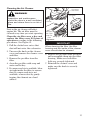
1
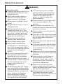
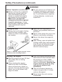
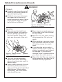
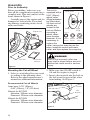
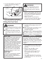
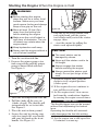
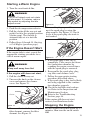
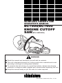
SHINDAIWA OWNER’S AND
OPERATOR’S MANUAL
EC7500/EC7600
ENGINE CUTOFF
SAW (EPA VERSION)
USE ONL
SHINDAIY GENUINE
WA BLA
No perfor
DES
mance
guaran
tee withou
Shinda
t using
iwa blades
.
No-load
revolution
speed:
4180 min-1
Use reinfor
ced abrasi
(rpm)
useable
ve blades
perime
with maxim
ter velocit
um
y of 248
ft/sec.
Maximum
blade diame
Maximum
blade thickn ter: 12 in.
Arbor diame
ess: 0.16
ter: 1 inch
in.
genuine
EC7500
WARNING!
■ Read this manual and familiarize yourself with its contents.
■ This unit is designed primarily for cutting construction materials and metal
according to the type of cutting wheel installed.
■ To minimize the risk of injury to yourself and others, always wear hearing
protection, a dustproof mask, goggles and a helmet when operating this unit.
■ Keep this manual handy so you can refer to it when required.
Part Number 68002-94310 Rev. 12/02
Contents
Page
Labels and Symbols
Attention Statements ............................ 2 The following are symbols that appear
Labels and Symbols ............................. 2 on the unit.
Safety Precautions ................................ 3
Read and follow the
operator’s manual. Failure
Safety/Operation Information Labels ... 7
to do so could result in
Unit Description ................................... 8
serious injury.
Technical Specifications ...................... 9
Always wear hearing
Assembly ............................................. 10
protection, a dustproof
Filling the Fuel Tank ......................... 11
mask, goggles and a
Starting/Stopping the Engine ........... 12
helmet when operating
Operation ............................................. 14
this unit.
Inspection and Maintenance ............. 16
Fuel Filler
Long Term Storage ............................ 23
Troubleshooting ................................. 24
Emission Warranty Statement .......... 25
Shindaiwa Inc. reserves the right to make
changes to products without prior notice, and
without obligation to make alterations to units
previously manufactured.
Attention Statements
Throughout this manual are special
“attention statements”.
WARNING!
A statement preceded by the word
“WARNING” contains information
that should be acted upon to
prevent serious injury.
CAUTION!
A statement preceded by the word
“CAUTION” contains information
that should be acted upon to
prevent unit damage.
IMPORTANT!
A statement preceded by the word
“IMPORTANT” is one that possesses
special significance.
NOTE:
A statement preceded by the word
“NOTE” contains information that is
handy to know and may make your
job easier.
2
Choke
The following symbols are meant to
provide important reminders.
Be aware of kickback!
Kickback may force the
cutting-off wheel up and
back toward the operator
with a lightning-fast
reaction. Kickback can
occur whenever the upperhalf of the cutting-off wheel
touches an object while
operating the unit.
Be aware of thrown
objects!
WARNING!
Using this cut-off saw, or any
other high-speed power tool, can
be hazardous. As a result, you
must employ special safety
precautions to reduce the risk of
injury or fire.
Safety Precautions
WARNING!
Before Operation
■ Children and people who do not
understand this manual must
not use this unit.
■ Never allow other people or
animals to be near the unit
when starting or operating.
■ Never touch a rotating cut-off
wheel.
■ Operate the unit only in a well
ventilated area.
■ Never operate the unit in a
closed area such as a room,
warehouse or tunnel. Running
the unit in a closed area may
cause serious illness or even
death due to exhaust gas.
■ Never allow any people or
animals near exhaust gas.
■ Never inhale exhaust gas.
■ Never make unauthorized
modifications or alterations to
any of the components of the
unit, and never operate the unit
without the wheel guard or
muffler.
■ This unit is designed for oneman operation and must be
operated by only one person.
■ Never operate the unit when
you are tired or under influence
of any substance that could
impair vision, dexterity or
judgement.
■ When operating the unit, always
wear snug-fitting clothing, safety
gloves, safety non-skid footwear,
hearing protection, a dust-proof
mask, a helmet and goggles.
Never wear floppy clothing,
shorts, sandals or accessories
that could become entangled.
■ To minimize the risk of sparks
igniting clothing while operating
the unit, wear clothing made of
leather, wool, tightly-woven
cotton, or cotton treated with
flame-retardant.
■ Never use any cut-off wheel that
is not recommended in this
manual.
■ Do not start or operate the unit
unless you have a clear work area
and secure footing.
■ Never smoke or use fire near the
unit or its fuel.
■ Since the muffler and exhaust gas
become very hot, make sure there
are no flammable substances
near the unit.
■ Never run the unit if you discover
a fuel leak.
■ A first-time operator should obtain
practical instruction from a dealer
or an experienced user before
using the unit.
■ Make sure all the components are
in place and the bolts are securely
fastened.
■ Make sure the cut-off wheel is
securely fastened and is not
damaged. Never use a cut-off
wheel with cracks, distortion, or
one that is unbalanced.
■ Make sure the belt tension is
properly adjusted and the wheel
guard, belt guard and clutch cover
are securely assembled.
■ Always inspect the front handle,
rear handle and wheel guard
before use, and never use the unit
if the parts are damaged.
3
Safety Precautions (continued)
WARNING!
Before Operation (continued)
■ Before cutting into a material,
familiarize yourself with the
risks associated with dust,
fumes, or mists that may be
generated during operation.
Make sure you provide
adequate protection against
harmful emissions. A highperformance respirator and/or
water attachment may be
required.
■ Do not use the cut-off saw to cut
or disturb asbestos or products
containing or wrapped in asbestos. If you believe you might be
cutting asbestos, contact your
supervisor.
Fueling the Unit
■ Mixing fuel and engine fueling
must be done outside, and
where no other combustibles
are nearby.
■ Open the fuel cap slowly to
release any possible build-up of
pressure.
■ Never refuel when the unit is hot.
Allow to cool before refueling.
■ Never fuel when the engine is
running.
■ After fueling, wipe all spilled fuel.
Cutting metal may cause sparks
from the cut-off wheel and may
ignite spilled fuel which could
result in serious injury.
Figure 1. Start the engine at least 10 feet
(3 meters) from a fueling location.
Starting The Engine
■ Start the engine at least 10 feet
(3m) away from a fueling
location.
■ When starting the engine,
make sure the cut-off wheel
does not touch any object or
ground. As soon as the engine
starts, the cut-off wheel may
begin to rotate.
■ Start the engine according to the
instructions in this manual. Start
the engine on a firm, stable
surface. Make sure the area is
clear of bystanders. Starting the
engine must be done by only
one person without any
assistance.
■ The cut-off wheel should not
rotate at engine idle. If it does,
reduce idle speed.
■ Never leave the unit running
unattended.
4
Safety Precautions (continued)
WARNING!
Kickback
■ Kickback may force the cut-off
wheel up and back toward the
operator lightning-fast.
■ Kickback can occur whenever
the upper half of the cut-off
wheel touches an object. Never
cut an object using the upper
half of the cut-off wheel.
EC7500.14
Figure 2. Always be aware of, and
prepared for, kickback.
Operation
■ The unit must be held firmly
with both hands, one hand on
the rear handle, the other on
the front handle. Never hold
onto any other part of the unit.
■ Never impact or apply pressure
to the sides of the cut-off wheel
for any reason.
■ Maintain firm and stable footing
during operation. Do not overreach.
■ When working in a group, make
sure operators are least 30 feet
(10 meters) away from each
other.
Figure 3. Always operate
below chest level.
EC7500.17
■ This unit must be operated
below chest level. Operating
above chest level may result in
serious injury.
■ If you drop the unit or strike it
against a hard surface, stop the
engine immediately and inspect
for damage. If you discover
damage, have it repaired before
you return the unit to service.
■ Check the fuel filler cap regularly
during operation to make sure it
remains securely tightened.
■ When cutting vertically, the unit
should be positioned horizontally or with the wheel side tilted
slightly down. When cutting
horizontally, the recoil starterside should face up.
5
Safety Precautions (continued)
WARNING!
Operation (continued)
■ If you discover fuel leakage,
immediately stop the engine.
■ Cutting may cause sparks from
the cut-off wheel. Make sure
there is no flammable substances nearby.
■ Never cut live electrical wires.
The shock you might receive
could be very serious.
■ Do not touch hot parts such as
the muffler or cylinder. You
could burn yourself severely.
■ The cut-off wheel gets hot while
cutting. Never touch the wheel
immediately after cutting. You
could burn yourself severely.
■ While the engine is running,
never touch high voltage parts
such as the spark plug cap and
plug cord.
Stopping The Engine
■ The cut-off wheel coasts for a
while after the engine is
stopped. Keep hold of the unit
firmly until the wheel stops
completely and then place it on
the ground.
Inspection and Maintenance
■ Before performing any inspection,
maintenance, repair or cleaning
of the unit, make sure engine and
cut-off wheel are completely
stopped and cooled down.
■ Inspection and maintenance
operations should be done in a
well ventilated location and where
there are no combustibles
nearby.
■ When replacing parts, always use
Shindaiwa genuine parts. Using
non-Shindaiwa genuine parts
may result in serious injury.
■ Inspection and maintenance
operations not mentioned in this
manual should be performed by
an authorized Shindaiwa dealer.
Transport and Storage
■ When carrying the unit, make
sure engine and cut-off wheel are
completely stopped.
■ Carry the unit with the front
handle and with cut-off wheel
facing rearward.
■ When storing the unit, make sure
the cut-off wheel is removed and
the unit is placed on a secure, dry
place.
■ Keep the unit away from children.
■ When storing the unit for more
than a few days, empty the fuel
tank completely.
■ Store gasoline and mixed fuel in
a closed, dry place and where
combustibles are not nearby.
6
Safety and Operation Information Labels
IMPORTANT!
Make sure all safety and operation
information labels are undamaged
and readable. Immediately replace
damaged or missing safety and
operation information labels, which
are available from your authorized
Shindaiwa dealer.
T
TURN THE KNOB ALL
THE WAY TO FREE
OR LOCK THE GUARD
FREE
LOCK
DECOMPRESSION
VALVE
PRIMER
EC7500.18
BELT
DIRECTION
ENGINE START PROCEDURES
No performance guarantee without
using genuine Shindaiwa blades
No-load revolution speed: 4220 min-1 (rpm)
Use reinforced abrasive blades with
maximum useable perimeter velocity of:
15,749 ft/min.(4800 m/min.)
EC7500
USE ONLY GENUINE
SHINDAIWA BLADES
No performance guarantee without
using genuine Shindaiwa blades
No-load revolution speed: 3680 min-1 (rpm)
Use reinforced abrasive blades with
maximum useable perimeter velocity of:
15,749 ft/min.(4800 m/min.)
Max. blade diameter: 12" (305mm)
Max. blade thickness: 0.157" (4.0mm)
Standard arbor: 0.86" (22mm),
others available; see owner’s manual
EC7600
6. Make sure the CHOKE knob is
pressed IN.
7. Make sure the DECOMPRESSION
valve is pressed IN.
8. Pull the recoil starter.
9. Once the engine starts, pull back
the throttle lever slightly to idle
(the CHOKE knob will
automatically go back IN).
HE KNOB SECUR
NT
ELY
TE
!
GH
TI
USE ONLY GENUINE
SHINDAIWA BLADES
1. Press PRIMER bulb 4–5 times,
or until fuel is in the bulb.
2. COLD ENGINE: Pull the CHOKE
knob OUT.
WARM ENGINE: Pull the CHOKE
knob once, then press it back IN.
3. Press the DECOMPRESSION
valve IN.
4. Place OFF/ON switch to “ON”.
5. Pull the recoil starter until you
hear first firing.
Max. blade diameter: 14" (355mm)
Max. blade thickness: 0.177" (4.5mm)
Standard arbor: 0.86" (22mm),
others available; see owner’s manual
Be aware of
kickback!
Be aware of
thrown objects!
IMPORTANT!
Read the
operator’s
manual
Wear eye,
hearing, and
breathing
protection
● Clean and inspect the filter
at least once a day.
● Make sure the filter
screw is tight.
● Use only 2-cycle
mixed fuel.
GASOLINE TO FUEL
OIL RATIO—50:1
USE ONL
SHINDAIY GENUINE
No perfor WA BLA
DES
mance
using
guaran
genuine
tee
Shindaiwa without
No-load
blades
revolu
Use reinfo tion speed: 4180
min-1 (rpm)
maximumrced abrasive
blades
with
15,749 useable perim
ft/min.(4800 eter veloci
ty of:
m/min.)
Max. blade
Max. blade diameter: 12"
(305mm)
Standard thickness: 0.157"
arbor:
others availab 0.86" (22mm(4.0mm)
le; see owner ),
’s manua
l
ON
EC7500
OFF
EC7500.1
Figure 4
7
Unit Description
Air Cleaner
Cover
Muffler
Carburetor Idle
Adjustment Screw
Choke
Belt Guard
EC7500.18
Rear
Handle
Primer
Pump
Decompression
Valve
Wheel Guard
Lock Knob
Clutch Cover
Front
Handle
Recoil
Starter
Throttle
Trigger
Lockout
Cut-off Wheel
EC7500.1A
Cylinder
Cover
Fuel Filler
Cap
Figure 5
8
ON/OFF
Switch
Throttle
Trigger
Technical Specifications
Engine Type ........................... 2-Cycle,
vertical-cylinder, air-cooled
Power Transmission .......... Automatic
centrifugal clutch, V-ribbed belt
Displacement ....... 4.5 cu. in. (73.5cc)*
Anti-Vibration System ............. Unified
handles with 7-point support
Bore x Stroke .. 2 x 1.4 in. (51 x 36mm)
Max. Power Output** .. 4.5 hp (3.3kW)
Recommended Engine Idling
Speed ................ 2,500 min-1 (rpm)**
Recommended Maximum Engine
Speed ............. 10,550 min-1 (rpm)**
Maximum Cutting Depth, EC7500
Abrasive Wheel
12 in. (305mm) ........... 4 in. (102mm)
Diamond Wheel
12.5 in. (320mm) .... 4.4 in. (109mm)
Maximum Cutting Depth, EC7600
Abrasive Wheel
13.9 in. (355mm) ........ 5 in. (127mm)
Diamond Wheel
14.1 in. (360mm) .... 5.1 in. (129mm)
Rated Spindle Speed†
EC7500 ............... 3,800 min-1 (rpm)
EC7600 ................ 3,320 min-1 (rpm)
Maximum Spindle Speed†
EC7500 ................ 4,220 min-1 (rpm)
EC7600 ............... 3,680 min-1 (rpm)
Maximum Peripheral Wheel Speed†
EC7500 .... 13,300 ft/min. (67.5m/sec)
EC7600 .... 13,500 ft/min. (68.0m/sec)
Speed Reduction Ratio
EC7500 .................................. 2.50:1
EC7600 .................................. 2.87:1
Safety Devices ......... Throttle lock-out,
wheel guard
Dry Weight (without wheel)
EC7500 .................... 22 lbs (10.0kg)
EC7600 .................... 23 lbs (10.5kg)
Dimensions (L x W x H)
EC7500 ............ 29.1 x 8.6 x 14.7 in.
(740 x 220 x 375mm)
EC7600 ............ 30.1 x 8.6 x 15.3 in.
(765 x 220 x 390mm)
Sound Pressure Level†
EC7500 ........................... 101 dB (A)
EC7600 ........................... 101 dB (A)
Sound Power Level††
EC7500 ........................... 108 dB (A)
EC7600 ........................... 111 dB (A)
Vibration Level§
Front handle (idle/rated spindle)
EC7500 .................. 6.96/5.48m/sec2
EC7600 .............. 10.09/10.49m/sec2
Rear handle (idle/rated spindle)
EC7500 ................ 8.61/14.60m/sec2
EC7600 ................ 8.93/13.70m/sec2
Recommended Cut-off Wheels
EC7500, abrasive ..... 12 in. (305mm) dia
EC7500, diamond .. 12.5 in. (320mm) dia
EC7600, abrasive .. 13.9 in. (355mm) dia
EC7600, diamond .. 14.2 in. (360mm) dia
Type of Fuel ........... Unleaded gasoline
plus 2-cycle engine oil (50:1)
Arbor Sizes ..................... 0.78" (20mm),
0.86" (22mm), and 1.0" (25.4mm)
Fuel Tank Capacity ................... 800ml
*
Carburetor Type ................ Diaphragm
Ignition System ................... Electronic
Spark Plug ................ Champion, CJ6Y
Engine Starting/Stopping ..................
Toggle switch, recoil starter
Measured in accordance with EN ISO 11201:
1995.
** Measured in accordance with ISO 7293: 1983.
† Measured with 305mm wheel (EC7500) and
355mm wheel (EC7600).
†† Measured in accordance with EN ISO 3744:
1995.
§ Measured in accordance with EN 28662-1:
1992.
9
Assembly
Prior to Assembly
IMPORTANT!
Before assembling, make sure you
have all the components required for a
complete unit. This unit consists of the
items shown in Figure 6.
Carefully inspect the engine unit for
damaged or loosen bolts. If you find
any damage or missing items, check
with your dealer.
This unit is
Collar
Drive Shaft
equipped with a
0.86" (22mm)
wheel collar.
Wheel adapters
for 20mm and
25.4mm cut-off
wheels are
located in the
Flange
Snap
tool set. Before
Ring
EC7500.49
mounting a
wheel, determine its arbor
diameter. If it is 20mm 22mm 25.4mm
Collar Collar Collar
necessary to
replace the
collar, remove the snap ring on the
arbor, install the correct size arbor
collar, and then replace the snap ring.
EC7500.45
Engine Unit
EC7500.19
WARNING!
Tool Set
Instruction
Manual
Figure 6
Mounting the Cut-off Wheel
1. Select a cut-off wheel for your work
according to the following chart.
Refer to the wheel manufacturer’s
manual for additional information.
Use of the incorrect collar size
may lead to wheel failure and unit
failure that could result in serious
injury.
2. Make sure the ON-OFF switch is
Off and the engine is stopped.
3. Insert a hex wrench into the hole in
the belt guard to prevent the arbor
from turning. See Figure 7.
Recommended Cut-off Wheels
Belt
Guard
Inner bore: 0.78" (20mm),
0.86" (22mm), 1.0" (25.4mm)
Hex
Wrench
Wheels for EC7500
Abrasive: 305mm outer diameter
Diamond: 320mm outer diameter
Wheels for EC7600
Abrasive: 355mm outer diameter
Diamond: 360mm outer diameter
EC7500.20A
Figure 7.
10
4. Loosen bolt with the wrench and
remove bolt and outer flange.
See Figure 8.
WARNING!
Using an inappropriate cut-off
wheel may cause the wheel to
break and may result in serious
injury.
Outer
Flange Bolt
Tighten
Loosen
EC7500.20
Figure 8
5. Place cut-off wheel so the inner
bore is properly set onto the collar.
6. Replace outer flange and bolt, and
then, while holding hex wrench in
the hole in belt guard, tighten the
bolt with wrench.
7. Make sure the cut-off wheel is
securely fastened. Spin the wheel
to make sure it does not wobble.
Filling the Fuel Tank
WARNING!
■ When filling the fuel tank, make
sure the engine is stopped and
cool.
■ Filling the fuel tank or mixing
fuel and oil must be done in a
place where there is no risk of
fire.
CAUTION!
Some gasolines contain alcohol as
an oxygenate! Oxygenated fuels
may cause increased operating
temperatures. Under certain
conditions, alcohol-based fuels may
also reduce the lubricating qualities
of some mixing oils. Never use any
fuel containing more than 10%
alcohol by volume! Generic oils and
some outboard motor oils may not
be intended for use in high-performance air-cooled 2-cycle engines
and should never be used in your
Shindaiwa engine.
CAUTION!
This engine is designed to operate
on a 50:1 mixture consisting of
unleaded gasoline and premium 2cycle mixing oil only.
■ Use only fresh, clean unleaded
gasoline with a pump octane of 87
or higher.
■ Mix all fuel with a premium 2-cycle
air-cooled mixing oil at a 50:1
gasoline/oil ratio.
Examples of 50:1 mixing quantities
■ 1 gallon gasoline to 2.6 oz. mixing oil.
■ 5 liters gasoline to 100ml mixing oil.
IMPORTANT!
Mix only enough fuel for your immediate needs. If fuel must be stored
longer than 30 days and oil with fuel
stabilizer is not used, it should first be
treated with a fuel stabilizer such as
StaBil™.
1. Use a container to pre-mix gasoline
and oil. Pour oil in first, then add
gasoline.
2. Remove the fuel filler cap by
turning counterclockwise.
3. Fill the tank with the mixed fuel,
then tighten the fuel filler cap
securely.
4. Any spilled fuel must be wiped up
completely. Make sure the unit has
no fuel leaks.
11
Starting the Engine When the Engine is Cold
WARNING!
■ Before starting the engine,
place the unit on a clean, level
surface. Make sure you have
good secure footing and always
keep a firm grip on the unit.
■ Move at least 10 feet (3m)
away from the fueling site
before starting the engine.
■ Make sure the cut-off wheel is
well clear of obstacles. The cutoff wheel may rotate when the
engine starts.
EC7500.22
Figure 10.
7. Grip the recoil starter handle with
your right hand, pull the starter
cord slowly until you feel the starter
engage, then…
8. …start the engine by pulling the
starter cord upward rapidly.
■ Keep bystanders well away.
■ Never start the engine without a
cut-off wheel installed.
1. Turn the on-off switch On.
2. Depress the primer pump a few
times repeatedly until the primer
pump is almost filled with fuel.
See Figure 9.
Choke
Primer
Pump
CAUTION!
■ The recoil starter can be
damaged by abuse.
■ Never pull the starter cord to its
full length.
■ Always engage the starter
before cranking the engine.
■ Always rewind the starter cord
slowly. Do not just let go of the
cord.
9. When the engine fires, push the
choke in to its original position
(choke open).
10. If the engine does not continue to
run, pull the recoil again.
EC7500.21
Figure 9
3. Push the decompression valve In.
4. Pull the choke all the way out
(choke closed). The throttle will
automatically be set to fast idle.
See Figure 9.
5. Place the unit on firm ground.
6. Secure the unit by placing your
right foot inside the rear handle
and your left hand on the front
handle. See Figure 10.
12
11. As the engine starts, clear excess
fuel from the combustion chamber
by revving the engine several times.
IMPORTANT!
The throttle trigger can not be moved
without first depressing the lockout
lever.
Operating the throttle will automatically disengage the fast idle setting.
12. Let the engine run at idle speed for
2-3 minutes to warm up.
Starting a Warm Engine
1. Turn the on-off switch On.
WARNING!
The cut-off wheel must not rotate
at idle speed. If it rotates, reduce
idle speed by adjusting the idle
adjust screw.
EC7500.24
Figure 12
4. Remove the plug cap and disconnect the spark plug by using the
3. Pull the choke all the way out and
plug wrench. See Figure 13. Check
push it back to the original position
to see if the spark plug electrode is
(choke open). The throttle is
fuel-soaked.
automatically set at a fast idle
position.
2. Push the decompression valve in.
4. Follow Steps 5 though 12, Starting
a Cold Engine (previous page).
If the Engine Doesn’t Start
If the engine fails to start, repeat the
appropriate starting procedure for a
cold or warm engine.
WARNING!
Keep well away from fire!
If the engine still does not start,
1. Pull the choke all way out.
2. Unscrew the knob on the cleaner
cover and remove the cleaner
cover. See Figure 11.
Figure 13
EC7500.25
5. If the spark plug is wet, dry it
completely. Clear excess fuel from
the combustion chamber by
cranking the engine several times
with the spark plug is removed.
6. Reassemble the spark plug, plug
cap, filter and cleaner cover.
7. Follow the appropriate starting
procedure described above.
8. If the spark plug is dry, fuel is likely
not being supplied to the combustion chamber properly.
■ Check the fuel filter and carburetor. Refer to the Inspection and
Maintenance Section.
■ Refer to the Troubleshooting
Section, page 24.
Choke
If the engine still does not start,
contact your Shindaiwa dealer.
EC7500.23
Figure 11
Stopping the Engine
3. Unscrew the two bolts securing the
filter element, remove the filter
element. See Figure 12.
Let the engine run at idle speed for 2-3
minutes, then turn the on-off switch
Off.
13
Operation
Adjusting Wheel Guard Angle
WARNING!
■ Never permit bystanders or
animals near the unit when
starting or operating the unit.
■ Be aware of kickback!
Kickback may force the cut-off
wheel up and back toward the
operator lightning-fast. Kickback can occur whenever the
upper half of the cut-off wheel
touches an object. Never cut
an object using the upperhalf of the cut-off wheel.
Adjust the position of the wheel guard
so that fragments will not fly toward
you if the wheel fractures. To reposition the wheel guard, loosen the lock
knob (counterclockwise). When the
wheel guard is positioned correctly,
securely tighten the lock knob.
See Figure 14.
Wheel Guard
Free
Wheel
Guard
Wheel Guard
Locked
Lock
Knob
■ When operating, always wear
snug-fitting clothing, safety
gloves, safety non-skid
footwear, hearing protection, a
dust-proof mask, a helmet and
goggles.
EC7500.27
Figure 14
WARNING!
When using the cut-off saw, the
wheel guard must be securely in
position as a protection against a
broken wheel. If the wheel guard
is not in place, a broken wheel
could project fragments at high
speed and strike you or others,
possibly resulting in serious
injury.
Wet or Dry Operation
This unit is designed to be operated
for either dry or wet cutting. A water
dust-suppression kit is available for
this unit but is not supplied in the
unit packaging. Please refer to the
assembly and operating instructions
supplied with the water dust-suppression kit.
14
Cutting
This unit performs most efficiently
when cutting between 8,500 and 9,500
min-1 (rpm). While running the engine
at full throttle, apply slight pressure to
the cut-off wheel against an object so
that engine speed stays at 8,500–9,500
min-1 (rpm). Too much pressure to the
wheel will lower wheel speed, reducing cutting efficiency considerably.
1. Make sure you have a clear work
area and secure footing.
2. Position the cut-off wheel vertically
to an object. Start cutting at a low
speed and then gradually accelerate the speed.
Reversing cutting head for flush cutting operations
WARNING!
Before performing any work on the cut-off saw, make sure the engine is
stopped and the ignition switch is OFF.
Remove Cutting Wheel
Belt Guard
Loosen
Two Bolts
Figure 17
Tension Screw
Tension
Indicator
Figure 15
NOTE:
For units equipped with a water kit,
loosen the (2) water nozzles and
disconnect the main water line from
the double nozzle.
1. Remove the cutting wheel (See
pages 10 and 11). Using a Phillips
screwdriver, loosen the tension
screw until the tension indicator is
all the way to the front of the scale.
See Figure 15.
6mm SocketHead Bolts
3. Using a 6mm hex wrench, remove
the two belt guard bolts and slide
the belt guard forward to remove.
See Figure 17.
Figure 18
Tension Screw
Mount
4. Remove the blade mount from the
mounting surface and rotate the
blade mount 1800, then remount to
the right hand side of mounting
surface. See Figure 18.
Figure 16
2. Back off tension screw another 4-5
turns so that adequate clearance is
achieved where the tension screw
contacts the mount when the mount
is turned over. See Figure 16.
15
Reversing cutting head for flush cutting operations (cont.)
6mm SocketHead Bolts
Figure 20
Figure 19
5. Making sure that the drive belt is
fully engaged in the drive pulleys,
slide the belt cover on and install
the two socket-head bolts into the
left-hand side of the mounting
surface only until the bolts bottom
on the belt cover. See Figure 19.
6. Adjust the tension screw until the
tension indicator is in the middle of
the scale. See Figure 20.
7. Tighten the two mounting bolts
securely.
8. Reconnect the main water line,
adjust and retighten water nozzles
(if equipped with a water kit).
9. Reinstall the cutting wheel.
Inspection and Maintenance
MAINTENANCE, REPLACEMENT, OR REPAIR OF EMISSION CONTROL
DEVICES AND SYSTEM MAY BE PERFORMED BY ANY REPAIR ESTABLISHMENT OR INDIVIDUAL. HOWEVER, WARRANTY REPAIRS MUST BE PERFORMED BY A DEALER OR SERVICE CENTER AUTHORIZED BY SHIN-DAIWA
KOGYO, LTD. AND USE OF PARTS THAT ARE NOT EQUIVALENT IN PERFORMANCE AND DURABILITY TO AUTHORIZED PARTS MAY IMPAIR THE
EFFECTIVENESS OF THE EMISSION CONTROL SYSTEM AND MAY HAVE A
BEARING ON THE OUTCOME OF THE WARRANTY CLAIM.
Inspection and Maintenance Requirements
Item
What to Do
Air Cleaner
Clean
Daily
✔
Cut-off Wheel
Check & Sharpen
✔
Bolts/Screws
Check & Retighten
✔
Fuel Cap
Check Leakage
✔
Fuel Tank
Check Leakage
✔
Wheel Guard
Check Function
✔
Weekly Monthly As Req’d
Clutch Bearing Grease
✔
Belt
Check and Adjust
✔
Spark Plug
Check and Clean
✔
Cylinder Fins
Clean
✔
Fuel Filter
Clean
✔
Carburetor
Adjust
16
✔
Cleaning the Air Cleaner
Unscrew
the Knob
WARNING!
Pre-filter
Inspection and maintenance
should be done in a well ventilated
place and where there is no risk of
fire.
Dust in the air cleaner will affect
engine life. The air filter must be
cleaned every time you start operating.
Clean the air filter once a day and
replace the filter every 20 hours of
operation according to the following
procedures. See Figure 21.
1. Pull the choke lever out so that
dust will not enter the carburetor.
2. Unscrew the knob on the cleaner
cover and remove the cleaner cover
and filter.
3. Remove the pre-filter from the
filter.
4. clean the pre-filter with soap and
water and let dry.
5. If compressed air is available, blow
air from inside the filter to remove
dust. If compressed air is not
available, remove dust by gently
tapping the element on a hard
surface.
EC7500.23
Choke
EC7500.48
Remove
the Filter
and Prefilter
Filter
EC7500.24
Figure 21
IMPORTANT!
When cleaning the filter, the filter
housing and the inside of the cleaner
cover should also be cleaned.
6. Replace the pre-filter onto the filter
and reassemble them into the filter
housing. Make sure both filter
bolts are securely tightened.
7. Reinstall the cleaner cover and
make sure the knob is securely
tightened.
17
Adjusting the Carburetor
Adjusting Idle Speed
It is not necessary to adjust the
carburetor when the unit is new.
Adjust the carburetor only when you
are sure it is necessary due to differences in working conditions such as
atmospheric pressure or temperature,
or change in unit conditions after
more than 10 hours of use.
If you are unfamiliar with carburetor adjustment techniques, ask your
dealer for advice.
Adjust the carburetor in accordance with the following procedures.
To adjust idle speed, turn the Idle
Adjust Screw with a screwdriver. See
Figure 22. Turn clockwise to increase
idle speed. Adjust idle speed so the
cut-off wheel does not rotate at idle.
Recommended idle speed:
2,200–2,600 min-1 (rpm)
EC7500.30
WARNING!
Figure 22
When adjusting the carburetor,
keep bystanders well away, and
make sure the cut-off wheel is
clear of any interference because
the wheel may rotate during
carburetor adjustment.
1. Prior to adjusting, clean the air
filter as described on the previous
page and then run the engine for a
few of minutes at idle speed to
warm up the engine.
18
High and Low Speed Needle
Cleaning Cylinder Fins
The high and low speed needle is
fixed and cannot be adjusted.
Spark Plug Maintenance
If the engine becomes hard to start or
if idle speed is unstable, inspect the
spark plug according to the following
procedures.
1. Remove the spark plug. Refer to
the procedures on page 13, If the
Engine Does Not Start…
2. Clean the electrode with a wire
brush. If necessary, adjust the
electrode gap. The gap should be
0.024" (0.6mm). See Figure 24.
0.024"
(0.6mm)
WARNING!
Before cleaning cylinder fins,
make sure the engine is cold.
Dust and debris may accumulate
between the cylinder fins and can lead
to engine overheating. In order to
maintain efficient service, cylinder fins
should be cleaned once every month.
Checking the Drive Belt
The transmission belt tends to loosen
and wear after a period of operation
and should be checked and adjusted
regularly according the following
procedures. If the belt is worn, torn,
cracked, scratched or otherwise
damaged, replace it with a new one
immediately.
Adjusting Belt Tension (Figure 25)
Figure 24
1. Loosen the two bolts in the belt
guard by one turn.
2. Turn the tension screw so the
washer aligns with the mark on the
clutch cover.
3. Tighten the two bolts in the belt
guard.
EC7500.34
Tension
Screw
Mark
Bolt
Belt Guard
Clutch
Cover
Washer
Figure 25
EC7500.34A
19
Replacing the Drive Belt
Checking the Cut-off Wheel
1. Loosen the tension screw. Loosen
the two bolts on the belt guard and
remove the belt guard by sliding it
to the right. See Figure 26.
2. Loosen the two bolts in the clutch
cover and remove the clutch cover.
3. Replace the old belt with a new one.
Slide
forward to
remove
EC7500.35
Tension
Screw
Clutch
Cover
WARNING!
Never use a wheel which has
breakage, cracks or distortion.
The wheel may break while
operating and may result in
serious injury.
Always check the condition of the cutoff wheel before starting the engine.
Make sure there are no breaks, cracks
or warps. See Figure 28.
A faulty wheel must be replaced
with a new one!
The tips of a diamond wheel should be
sharpened regularly to maintain
cutting efficiency. See page 22.
Belt Guard
Bolt
Figure 26
4. Reassemble the clutch cover and
the belt guard and adjust the belt
tension. Figure 27 illustrates the
components.
Cracks
Missing
Tips
Worn Tips
EC7500.36
EC7500.47
Figure 27
Distortion or Warps
Figure 28
20
Replacing the Cut-off Wheel
1. Make sure the ignition switch is Off
and the engine is stopped.
2. Insert a 6mm hex wrench into the
hole in the belt guard to prevent
the drive shaft from turning.
See Figure 29.
Replacing the Cut-off Wheel
WARNING!
Using the wrong size collar may
lead to failure of the wheel or the
unit and could result in serious
injury.
5. Remove the old wheel and install
the new one. Make sure the inner
bore is properly set onto the collar.
6. Replace the outer flange and bolt,
then holding the hex wrench in the
hole of the belt guard, tighten the
bolt with the wrench.
EC7500.20A
Belt Guard
7. Make sure the cut-off wheel is
securely fastened and does not
wobble.
Hex Wrench
Outer
Flange
WARNING!
Outer
Flange
Bolt
Make sure the replacement cut-off
wheel rpm rating is greater than
the speed indicated on the wheel
guard label.
Wrench
Label Showing
Direction of
Rotation
Tighten
Loosen
Label Showing Rated
and Maximum
Spindle Speed
EC7500.20
Figure 29
3. Loosen the outer flange bolt with
the wrench and remove the bolt
and outer flange.
4. Before mounting a cut-off wheel,
determine its arbor diameter. If
necessary, remove the snap ring
from the arbor, install the correct
collar, then re-install the snap ring.
EC7500.42
Diamond
Wheel
Wheel Guard
CAUTION!
Make sure the rotating direction of
wheel corresponds to the one
indicated on the wheel guard.
Make sure there is no dust around
the outer flange.
21
Sharpening a Diamond
Cut-off Wheel
While running the engine at low
speed, make about 10 passes at
cutting a concrete block or a soft
brick. Keep the block watered while
sharpening.
Lubricating the Clutch Bearing
Grease the clutch bearing every 20
hours of operation. Squeezing a
grease gun three times will deliver an
appropriate amount of grease.
See Figure 31.
Checking the Fuel Filter
EC7500.44
WARNING!
KEEP AWAY FROM FIRE OR
EXCESS HEAT!
1. Remove the fuel filler cap.
2. Take the filter out from the fuel
opening by using a hooked wire. If
the filter is hard and clogged with
debris, replace it with a new one.
See Figure 30.
CAUTION!
Make sure the fuel line is not
pierced by the hooked wire. The
fuel line can be easily damaged.
Hooked Wire
Fuel Filter
Fuel Filler
Cap
Figure 30
3. Put the filter back into the fuel
tank. Make sure the fuel tube is not
bent and the filter stays at the
bottom of the tank.
4. Put the fuel filler cap back and
tighten it securely.
22
Grease Gun
Figure 31
Long Term Storage
Whenever the unit will not be used for
30 days or longer, use the following
procedures to prepare if for storage:
■ Clean external parts thoroughly.
■ Drain all the fuel from the carburetor and the fuel tank.
IMPORTANT!
All stored fuels should be stabilized
with a fuel stabilizer such as StaBil™.
To remove the remaining fuel from the
fuel lines and carburetor and with the
fuel drained from the fuel tank…
1. Prime the primer bulb until no
more fuel passes through.
2. Start the engine and idle until it
stops running.
■ Remove the spark plug and pour
about 1/4 ounce of 2-cycle mixing
oil into the cylinder through the
spark plug hole. Slowly pull the
recoil starter 2 or 3 times so oil will
evenly coat the interior of the
engine. Reinstall the spark plug.
■ Before storing the unit, repair or
replace any worn or damaged parts.
■ Remove the air cleaner element
from the carburetor and clean it as
described on page 17, then reassemble the element.
■ Clean the exterior of the unit
thoroughly.
■ Store the unit is a clean, dust-free
area.
3. Repeat Steps 1 and 2 until the
engine will no longer start.
CAUTION!
Gasoline stored in the carburetor
for extended periods can cause
hard starting and could also lead
to increased service and maintenance costs.
23
Troubleshooting
PROBLEM
PROBLEM
The engine does not start.
Cutting performance is poor.
Make sure the fuel tank contains
with clean, fresh fuel (pg 11).
Make sure the choke is
pushed fully in.
Remove the spark plug (pg 13).
Make sure the air
cleaner is clean (pg 17).
Is the spark
plug wet?
Dry the
spark plug.
Inspect the
spark plug
(pg 19).
Pull the recoil
starter several
times to
remove fuel
from the
cylinder.
Is the spark
plug dry?
Replace the
fuel filter
(pg 22).
Make sure the cut-off wheel is
appropriate for your work.
Make sure the diamond
wheel is sharp.
Make sure the drive belt is
properly tightened (pg 19).
Make sure the carburetor is
is properly adjusted (pg 18).
If the above inspections and maintenance procedures do not
correct the problem, contact your Shindaiwa dealer for assistance.
24
The following statement only applies to United States and its territories
Shindaiwa Kogyo Co., Ltd.
Federal Emission Design And Defect Limited Warranty
Utility And Lawn And Garden Engines
Shindaiwa Kogyo Co., Ltd. warrants to the initial purchaser and each
subsequent owner, that this utility equipment engine (herein engine) is
designed, built and equipped to conform at the time of initial sale, to all
applicable regulations of the U.S. Environmental Protection Agency (EPA),
and that the engine is free of defects in materials and workmanship that would
cause this engine to fail to conform with EPA regulations during its warranty
period. This emission warranty is applicable in all States, except the State of
California.
For parts listed under PARTS COVERED, the dealer authorized by
Shindaiwa Kogyo Co., Ltd. will, at no cost to you, make the necessary
diagnosis, repair, or replacement of any defective emission-related component
to ensure that the engine complies with applicable U.S. EPA regulations.
MANUFACTURERS WARRANTY COVERAGE
When sold within the U.S., this engine’s emission control system is warranted for a period of two (2) years from the date this product is first delivered
to the original retail purchaser.
OWNER’S WARRANTY RESPONSIBILITIES
As the engine owner, you are responsible for the performance of the required maintenance listed in your owner’s manual. Shindaiwa Kogyo Co., Ltd.
recommends that you retain all receipts covering maintenance on your engine,
but Shindaiwa Kogyo Co., Ltd. cannot deny a warranty claim solely for the lack
of receipts or for your failure to ensure the performance of all scheduled
maintenance.
As the engine owner, you should however be aware that Shindaiwa Kogyo
Co., Ltd. may deny your warranty coverage if your engine or a part has failed
due to abuse, neglect, improper maintenance or unapproved modifications.
You are responsible for presenting your engine to the nearest dealer
authorized by Shindaiwa Kogyo Co., Ltd. when a problem exists.
If your Shindaiwa Dealer is unable to answer questions regarding your
warranty rights and responsibilities, you should then contact your Shindaiwa
Distributor.
For the name and telephone number of the Shindaiwa Distributor in your
area, please call Shindaiwa Inc. at (503) 692-3070 between the hours of 8:00
AM and 5:00 PM Pacific Standard Time.
25
PARTS COVERED
Listed below are the parts covered by the Federal Emission Design and Defect
Warranty. Some parts listed below may require scheduled maintenance and are
warranted up to the first scheduled replacement of that part. The warranted parts
include:
1. Carburetor Internal Components
• Valve Assembly-throttle, Jet, Metering Diaphram
2. Ignition System Components
• Ignition Coil
• Flywheel Rotor
The emission control system for your particular Shindaiwa engine may also
include certain related hoses and connectors.
LIMITATIONS
The Federal Emission Design and Defect Warranty shall not cover any of the
following:
(a) conditions resulting from tampering, misuse, improper adjustment
(unless they were made by the dealer or service center authorized by
Shindaiwa Kogyo Co., Ltd. during a warranty repair), alteration,
accident, failure to use the recommended fuel and oil, or not performing required maintenance services,
(b) the replacement parts used for required maintenance services,
(c) consequential parts used for required maintenance services,
(d) diagnosis and inspection fees that do not result in eligible warranty
service being performed, and
(e) any non-authorized replacement part, or malfunction of authorized
parts due to use of non-authorized parts.
MAINTENANCE AND REPAIR REQUIREMENTS
You are responsible for the proper use and maintenance of the engine. You
should keep all receipts and maintenance records covering the performance of
regular maintenance in the event questions arise. These receipts and
maintenance records should be transferred to each subsequent owner of the
engine. Shindaiwa Kogyo Co., Ltd. reserves the right to deny warranty coverage
if the owner has not properly maintained the engine. Shindaiwa Kogyo Co., Ltd.
will not deny warranty repairs, however, solely because of the lack of repair,
maintenance or failure to keep maintenance records.
26
MAINTENANCE, REPLACEMENT OR REPAIR OF EMISSION CONTROL
DEVICES AND SYSTEMS MAY BE PERFORMED BY ANY REPAIR
ESTABLISHMENT OR INDIVIDUAL; HOWEVER, WARRANTY REPAIRS
MUST BE PERFORMED BY A DEALER OR SERVICE CENTER AUTHORIZED
BY SHINDAIWA KOGYO CO., LTD. THE USE OF PARTS THAT ARE NOT
EQUIVALENT IN PERFORMANCE AND DURABILITY TO AUTHORIZED
PARTS MAY IMPAIR THE EFFECTIVENESS OF THE EMISSION CONTROL
SYSTEM AND MAY HAVE A BEARING ON THE OUTCOME OF A
WARRANTY CLAIM.
If other than the parts authorized by Shindaiwa Kogyo Co., Ltd. are used for
maintenance replacements or for the repair of components affecting emission
control, you should assure yourself that such parts are warranted by their
manufacturer to be equivalent to the parts authorized by Shindaiwa Kogyo Co.,
Ltd. in their performance and durability.
OBTAINING WARRANTY SERVICE
All repairs qualifying under this limited warranty must be performed by a
dealer authorized by Shindaiwa Kogyo Co., Ltd.
If any emission-related part is found defective during the warranty period, it is
your responsibility to present the product to an authorized Shindaiwa dealer.
Bring your sales receipts showing the date of purchase for this engine. The
dealer authorized by Shindaiwa Kogyo Co., Ltd. will perform the necessary
repairs or adjustments within a reasonable amount of time and furnish you with a
copy of the repair order. All parts and accessories replaced under this warranty
become the property of Shindaiwa Kogyo Co., Ltd.
To locate an authorized Shindaiwa dealer near you, contact your Shindaiwa
Distributor. For the name and telephone number of the Shindaiwa Distributor in
your area, please call Shindaiwa Inc. at (503) 692-3070 between the hours of 8:00
AM and 5:00 PM Pacific Standard Time.
THIS WARRANTY IS ADMINISTERED BY
Shindaiwa Inc.
11975 S.W. Herman Rd.
Tualatin OR. 97062
(503) 692-3070
27
Shindaiwa Inc.
11975 SW Herman Road
Tualatin, Oregon 97062
Telephone 503-692-3070
Fax
503-692-6696
www.shindaiwa.com
Shindaiwa Kogyo Co., Ltd.
6-2-11 Ozuka-Nishi
Asaminami-Ku, Hiroshima
731-3167, Japan
Telephone 81-82-849-2220
Fax
81-82-849-2481
©2002 Shindaiwa Inc.
Part Number 68002-94310
Shindaiwa is a registered
trademark of Shindaiwa Inc.