1
Table of Contents
Chapter 1: DVR Features ............................................................................................................................................................. 2
Chapter 2: Hardware Layout ....................................................................................................................................................... 2
2.1 Front Panel ...................................................................................................................................................................... 2
2.2 Rear Panel ....................................................................................................................................................................... 3
2.3 Remote Control................................................................................................................................................................ 3
Chapter 3: Installation................................................................................................................................................................ 4
Chapter 4: DVR System Boot ..................................................................................................................................................... 4
4.1 Display DVR Firmware Version ....................................................................................................................................... 4
4.2 Detecting Installed Hard Drive ......................................................................................................................................... 4
4.3 Format Hard Drive ........................................................................................................................................................... 5
4.4 Main Screen..................................................................................................................................................................... 5
Chapter 5:DVR Setup (Main menu) ............................................................................................................................................. 5
5.1 Camera Setup .................................................................................................................................................................. 6
5.2 Record Setup ................................................................................................................................................................... 6
5.3 Record Frame Rate .......................................................................................................................................................... 6
5.4 Video Quality................................................................................................................................................................... 7
5.5 Record Schedule .............................................................................................................................................................. 7
5.6 Sensor Setup .................................................................................................................................................................... 7
5.7 Hard Drive Setup ............................................................................................................................................................. 8
5.8 Miscellaneous Setup ........................................................................................................................................................ 9
5.8.1 Password Change ................................................................................................................................................. 9
5.8.2 Set Time............................................................................................................................................................. 10
5.8.3 Hidden Channel.................................................................................................................................................. 10
5.8.4 Audio port setup ................................................................................................................................................. 10
5.8.5 PTZ Setup .......................................................................................................................................................... 11
5.8.6 Image Parameters ............................................................................................................................................... 11
5.8.7 Password Enable ................................................................................................................................................ 11
5.8.8 VGA Setup......................................................................................................................................................... 12
5.9 Network Setup ............................................................................................................................................................... 12
5.10 Reset Menu.................................................................................................................................................................. 17
Chapter 6: Recording ................................................................................................................................................................. 17
6.1 Start Recording .............................................................................................................................................................. 17
6.2 Audio Recording ............................................................................................................................................................ 18
6.3 Stop Recording .............................................................................................................................................................. 18
6.4 Estimated Recording Length........................................................................................................................................... 18
Chapter 7: Playback ................................................................................................................................................................... 19
7.1 Playback Control ........................................................................................................................................................... 19
Chapter 8: USB Programming ................................................................................................................................................. 20
8.1 Install ............................................................................................................................................................................ 20
8.2 Program Interface .......................................................................................................................................................... 20
Chapter 9: Specifications ............................................................................................................................................................ 23
9.1 DVR.............................................................................................................................................................................. 23
9.1 Camera……………………………………………………………………………………………………………………..….23
Appendix .. ................................................................................................................................................................. 24
Q-SEE Product Warranty………………………………………………………………………………………………...……..……25
1
Chapter 1: DVR Features
l
9 BNC Camera Inputs,1 BNC Video Output
l
1 channel Audio input,1 channel Audio output
l
View and Operate over Network (Broadband Connection Required)
l
NTSC or PAL format.
l
Motion Detection with Sensitivity and Area Settings
l
Manual, Time Schedule Recording,alarm Recording,Motion Triggered Recording
l
Supports 500GB SATA Hard Drive.
l
Supports USB backup and playback by PC.
l
Supports PTZ Control via RS485 Port.
l
Supports Remote Control
l
Supports Fixed Hard Drive
l
Supports VGA Output
Chapter 2: Hardware Layout
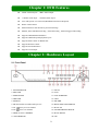
2.1 Front Panel
1 .POWER SWITCH
11. PAUSE
2. PWR LED
12. PLAY
3. IR RECEIVER
13. FAST FORWARD
4. HDD LED
14. STOP
5. SEARCH
15. RECORD
6. MUTE: Disable or Enable audio preview
16. MENU/EXIT/LEFT ARROW
7.CH-
: View previous channel
17. MOVE UP
8.CH+
:View next channel
18. SEL/EDIT/RIGHT ARROW
9. DISPLAY ALL CAMERAS
19. MOVE DOWN
10. FAST REWIND
20. PTZ
2
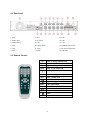
2.2 Rear Panel
1. Fan
7. CH1
13. CH7
2. Audio input
8. VGA Port
14. CH6
3. Video output
9. LAN
15. CH5
4. CH4
10. Audio output
16. RS485/Sensor/Alarm
5. CH3
11. CH9
17. DC Power Input Jack
6. CH2
12. CH8
18. USB Port
2.3 Remote Control
1-9
0
Select or enlarge Channel #1-9
Number
ALL
Display All Channels
Menu
Enter or exit setup menu
▲
Move up / left cursor
▼
Move down / right cursor
SEL
Select / modify item
Rewind
Play recording list
Audio
Audio input/output
Mute
Disable audio preview
Forward
●
Record
Pause
■
Stop
3
Chapter 3: Installation
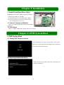
3. Install Fixed Hard Drive (Fig1)
NOTICE: Do not remove HDD while DVR is running.
I. Remove the DVR cover carefully.
II. Connect the power cord and data cable to HDD.
III. Use the provided screws to fix hard drive on the
rack, and then replace the cover.
3.1 Connect Cameras and Monitor
There are 9 camera inputs and 1 monitor output (BNC
connectors).
Fig1
3.2 VGA Output
There is 1 CRT or LCD monitor output with VGA connector.
Chapter 4: DVR System Boot
4. DVR System Boot
4.1 Display DVR Firmware Version
After connecting the power and turning on the power
V1.9
V-EN
switch the system will boot-up and display the version and
release date of the DVR firmware.
2008.3.20
4.2 Detecting Installed Hard Drive
CHECKING HDD……
MASTER [WDCWD3200AAJB-00T]
SLAVE……
DVR will detect the installed hard drive and display the
hard drive information.
4
4.3 Format Hard Drive
When the hard drive is installed in the DVR for the first time
CHECKING HDD……
MASTER [WDCWD3200AAJB-00T] -NEW- DVR
the DVR will request you to format the HDD, Otherwise the
DVR will not be able to record to the HDD.
FORMAT HDD CONFIRM
(SELECT)FORMAT /(MENU)CANCEL?
Press [SEL] to format or press [MENU] to cancel.
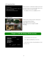
4.4 Main Screen
While the DVR is running the monitor will display the
view from the cameras as follows:
Bottom right: System Date and Time
Bottom left: System status. (Refer to 6.1 Start
Recording)
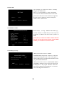
Chapter 5:DVR Setup (Main menu)
MAIN MENU
CAMERA SETUP
RECORD SETUP
RECORD FRAMERATE
VIDEO QUALITY
RECORD SCHEDULE
SENSOR SETUP
HARD DRIVE SETUP
MISCELLANEOUS SETUP
NETWORK SETUP
RESET MENU
(1)Press [MENU] to enter main menu.
NORMAL
(2)Use [▲UP] and [▼DOWN] to select items.
(3)Press [SEL] to modify setting and [MENU] to return
to previous or exit.
(
)MOVE
(SEL)SELECT
(MENU) EXIT
5
5.1 Camera Setup
1
ON
2 OFF
3 ON
CAMERA SETUP
4 ON
5 ON
6 ON
7 ON
8 ON
9 ON
(
(SEL)SELECT
)MOVE
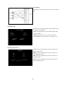
This DVR system supports up to 9 cameras. You can
configure which cameras are displayed or not displayed
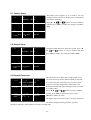
in real-time monitoring.
Press [▲, ▼,
and
] buttons to select a channel,
and then press [SEL] to modify the setting to be ON or
OFF.
(MENU) EXIT
5.2 Record Setup
1
ON
2 OFF
3 ON
RECORD SETUP
4 ON
5 ON
6 ON
7 ON
8 ON
9 ON
(SEL)SELECT
(MENU)EXIT
(
) MOVE
Configure which channel is allowed to record. Press [▲,
▼,
and
] buttons to select a channel, and then
press [SEL] to modify the setting to be ON or OFF.
5.3 Record Frame rate
1
5 FPS
2
5 FPS
3
5 FPS
RECORD FRAMERATE
TOTAL 45FPS
4
5 FPS
5
5 FPS
6
5 FPS
7
5 FPS
8
5 FPSN
9
5 FPS
(
)MOVE
(SEL)+
( □ )-
(MENU) EXIT
The total frame rate is 50fps (PAL)/ 60fps (NTSC). You
can set the frame rate for the channel which you selected
to record. If the sum of the frame rate you select for all
cameras is more than 50fps (PAL)/ 60fps(NTSC), the
DVR will automatically adjust the largest frame rate value
to a smaller value.
Press [▲, ▼,
and
] buttons to select a channel,
and then press [SEL] to increase the value or press
[■STOP] to reduce the value.
The higher frame rate used to record,the more natural the
movement will appear during play back, but more
hard drive disk space will be needed to save the recorded video.
6
5.4 Video Quality
MAIN MENU
CAMERA SETUP
RECORD SETUP
RECORD FRAMERATE
VIDEO QUALITY
RECORD SCHEDULE
SENSOR SETUP
HARD DRIVE SETUP
MISCELLANEOUS SETUP
NETWORK SETUP
RESET MENU
(
NORMAL
(SEL)SELECT
) MOVE
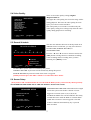
There are four video quality settings, Highest
\High\Normal\Low
The higher the video quality, the clearer the image will be
during playback. The lower the video quality, the more
space you will save on the hard drive
The video quality in view mode is not affected by the
video quality setting; these settings only affect the video
quality during playback of a recording.
(MENU)EXIT
5.5 Record Schedule
RECORD SCHEDULE
AM
PM
0…3…6…9…0…3…6…9
NO-RECORD
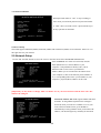
The time line indicates the hours of the day based on an
AM/PM clock. For each hour, you may select between
NO-RECORD, NORMAL-RECORD, or
SENSOR-RECORD.
Press the “▲” and “▼” arrows to maneuver and use the
[SEL] button to change between continuous recording,
sensor recording and no recording. Once you have
finished, press [MENU] to exit.
NORMAL-RECORD
s
(
)MOVE
SENSOR-SECORD
(SEL)SELECT
(MENU) EXIT
NO-RECORD: System will not record during this period.
NORMAL-RECORD: System will record continuously during this period.
SENSOR-RECORD: System will record when sensor is triggered.
[NOTE] You must press the “REC” button to record in these three modes.
5.6 Sensor Setup
[Note] Sensors and extension alarms do not come with the DVR system; you need to buy them separately.
SENSORED RECORD TIME and ALARM ON TIME are measured in seconds.
SENSORED SETUP
SENSORED RECORD TIME
30
ALARM ON TIME
OFF
H/W
SENSOR
SETUP
MOTION DETECTOR SETUP
(
) MOVE
(SEL)SELECT
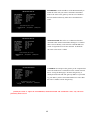
SENSORED RECORD TIME: This indicates the length
of time the system records after a motion or sensor
triggered event ends. (Time: 5,10,15,20,25,30)
ALARM ON TIME: This selection indicates how many
seconds the buzzer inside the DVR or extension alarm
sounds after a motion or sensor triggered event ends.
CONT: Continuous alarm until any key is pressed.
OFF: No alarm
(MENU)EXIT
7
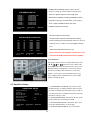
HARDWARE SENSOR SETUP: This is the sub
menu for setting up external motion sensor devices.
H/W SENSOR SETUP
CHANNEL-1
CHANNEL-2
CHANNEL-3
CHANNEL-4
CHANNEL-5
CHANNEL-6
CHANNEL-7
CHANNEL-8
CHANNEL-9
(
There are 3 different modes for sensor setting: NOT
TYPE:NORMAL-OPEN
NOT INSTALLED
NOT INSTALLED
NOT INSTALLED
NOT INSTALLED
NOT INSTALLED
NOT INSTALLED
NOT INSTALLED
NOT INSTALLED
CH5
CH6
CH7
CH8
CH9
ON
ON
ON
ON
ON
LEVEL
LEVEL
LEVEL
LEVEL
LEVEL
LEVEL2
LEVEL2
LEVEL2
LEVEL2
LEVEL2
LEVEL2
LEVEL2
LEVEL2
LEVEL2
It depends on what type of external sensor you are using. If
sensor’s output is NORMAL-OPEN, then select
NORMAL-OPEN mode in DVR.
(SEL)SELECT
) MOVE
INSTALLED, NORMAL-CLOSE and NORMAL-OPEN.
(MENU)EXIT
2
2
2
2
2
MOTION DETECTOR SETUP:
AREA
AREA
AREA
AREA
AREA
AREA
AREA
AREA
AREA
AREA
AREA
AREA
AREA
AREA
MOTION DETECTOR SETUP
CH1
CH2
CH3
CH4
CH5
CH6
CH7
CH8
CH9
(
ON
ON
ON
ON
ON
ON
ON
ON
ON
LEVEL: Sensitivity for motion detection. There are 3 levels of
sensitivity: Level 1, 2 and 3. Level 3 is the highest sensitivity
level.
AREA: Select motion detection active area.
[Note] You do not need to install any external sensors if you
(SEL)SELECT
) MOVE
ON/OFF: Enable or disable motion detection recording.
(MENU)EXIT
want to use the DVR’s internal motion sensor capability.
Area Selection:
The picture from a camera is divided into blocks, press
[▲, ▼,
and
] buttons to select a block, and
press [SEL] button to set the block to be active or not.
When the block is transparent, it’s active for motion
detection recording; when the block is covered by
shadow, it is not active for motion detection record.
Press “stop” button to disable all areas, press “All”
button to enable all areas
5.7 Hard Drive Setup
(1) OVERWRITE ENABLED: If you choose YES
(default setting), recording continues and overwrites
previous recordings when hard drive space is Full. If
you choose NO, the recording session stops when the
hard drive capacity is full.
(2) MASTER HDD SIZE: This shows the size of the
primary hard drive installed in the DVR.
(3) MASTER HDD USED: It shows the space used
on the first hard disk drive for recording.
(4) MASTER HDD FORMAT: If you format the
HARD DRIVE SETUP
OVERWRITE ENABLED
[ ON]
ST3160215A
MASTER HDD SIZE
160133MB
MASTER HDD SIZE
124931MB 78%
MASTER HDD FORMAT
SLAVE HDD SIZE
N/A
SLAVE HDD USED
N/A
SLAVE HDD FORMAT
(
) MOVE
(SEL)SELECT
(MENU) EXIT
8
hard drive, it will erase all the data recorded on the first hard drive.
(5) SLAVE HDD SIZE: This shows the space available on the secondary hard drive in the DVR.
(6) SLAVE HDD USED: This shows the space used on the secondary hard drive for recording.
(7) SLAVE HDD FORMAT: If you format this hard drive it will erase all the data recorded on the secondary
hard drive.
(8) Hard Disk Drive Format
When you press the “SELECT” key you will be prompted to input a Password when the hard drive format
menu appears.
Type Password (6) ::――――――
When you key in the correct password the following message will flash 3 times:
“password correct
Hard Disk Formatting…”
Otherwise the following error message will be displayed on the screen:
“Password Incorrect”
[Note] The Factory Default password is 111111.
5.8 Miscellaneous Setup
MISCELLANEOUS SETUP
PASSWORD CHANGED
SET TIME
HIDDEN CHANNEL
AUDIO PORT SETUP
PTZ SETUP
IMAGE PARAMETERS
PASSWORD ENABLE
VGA SETUP
(
) MOVE
(SEL)SELECT
[OFF]
[OFF]
800X600 60HZ
(MENU) EXIT
5.8.1 Password Change
This option allows you to change the system password.
The password must be composed with six characters.
All keys can be used as a password key except the
[MENU] key, which is used to exit.
[------]
CURRENT
NEW
PASSWORD
PASSWORD
CONFIRM
[------]
[------]
[NOTE] The Factory Default Password is 111111.
PASSWORD
9
5.8.2 Set time
You can change year /date /hour / minute / second by
using the SET TIME menu.
2007/11/11=year/month/day 17:50:01=hour/minute
/second .Use the REW and FWD buttons on the front
panel to move the cursor below the numbers right and
left. Then use the “SELECT” button to change the
numeric values of date & time.
SET TIME
2008/11/11
(
) MOVE
17:50:01
(SEL)SELECT
(MENU) EXIT
5.8.3 Hidden Channel
MISCELLANEOUS SETUP
CHANGE PASSWORD
SET TIME
HIDDEN CHANNEL
AUDIO PORT SETUP
PTZ SETUP
IMAGE PARAMETERS
PASSWORD ENABLE
VGA SETUP
(
) MOVE
[
4 ]
[CH4]
[OFF]
800X600 60HZ
(SEL)SELECT
In the example,selecting “HIDDEN CHANNEL”[4],
it means camera 4 is hidden and you can not preview
the picture of channel 4 but can record its picture on
HDD
[Note] when you enable the hidden channel function
you just can not preview the picture of the hidden
channel, you can still record on the channel.
(MENU) EXIT
5.8.4 Audio port setup
AUDIO PORT SETUP
[ 1 ]
[ ON ]
AUDIO PORT1-VIDEO CHANNEL
AUDIO PORT1-RECORD
(
) MOVE
(SEL)SELECT
(MENU) EXIT
When you move the cursor to “AUDIO
PORT-RECORD” and push the “SELECT” button the
option will be changed to OFF or ON .If the option is
ON the audio will be recorded into the hard drive when
you push the RECORD button.
When you move the cursor to “AUDIO PORT VIDEO
CHANNEL” and push “select” button, the option will
be changed to “2”. If you push “SELECT” button one
more time the option will be changed to “3” and once
more will change the channel to “4”.
10
For Example:
The hardware setup for the above screen is shown on the
left.
5.8.5 PTZ Setup
PTZ SETUP
SPEED
PROTOCOL
CAMERA-[ 1 ]
[4800 ]
[PELCO-D]
ID-[ 1 ]
(
) MOVE
(SEL)SELECT
This DVR can control speed dome cameras (PTZ) which
are connected to the DVR.
SPEED: Set the band rate of each channel (4800, 9600,
19200, or 38400)
PROTOCOL: Select PELCO-P or PELCO-D protocol.
CAMERA&ID: Select the camera (1-4); ID set (1-32)
(
)CAM ID
(MENU)EXIT
5.8.6 Image Parameters
CAMERA1
CON
BRI
HUE
SAT
(
)MOVE
64%
64%
64%
64%
(
)+(
)-
(MENU) EXIT
CON: press left or right button of remote control to set
image contrast value
BRI: press left or right button of remote control to set
image brightness value
Hue: press left or right button of remote control to set
image hue value
SAT: press left or right button of remote control to set
image saturation value
11
5.8.7 Password Enable
MISCELLANEOUS SETUP
enter menu you will need password. If password enable
CHANGE PASSWORD
SET TIME
HIDDEN CHANNEL
AUDIO PORT SETUP
PTZ SETUP
IMAGE PARAMETERS
PASSWORD ENABLE
VGA SETUP
(
) MOVE
When password enable is “ON” to stop recording or
[
4 ]
[ CH4 ]
[ OFF ]
800X600 60HZ
(SEL)SELECT
is “OFF” there’s no need to enter a password when you
do any operation on the DVR.
(MENU) EXIT
5.8.8 VGA Setup
The DVR supports 800x600 (60HZ),1024X768 (60HZ) and 1280x1024 (60HZ) VGA resolutions. Please set it to
the right value for your monitor.
5.9 Network Setup
Use the “▲” and “▼” buttons to move the cursor to the other items in the NETWORK SETUP menu
MAC ADDRESS: In a local area network (LAN) the
NETWORK SETUP
MAC (Media Access Control) address is your
computer’s unique hardware identity code. (On an
<00.11.22.33.44.55>
MAC ADDRESS
[STATIC]
IP ALLOCATION
[192.168.1.100]
IP ADDRESS
Ethernet LAN it is the same as your Ethernet
[255.255.255.0]
SUBNET MASK
[192.168.1.1]
GATEWAY
address.)When you are connected to the Internet from
[0.0.0.0]
DNS1 ADDRESS
[0.0.0.0]
DNS2 ADDRESS
your computer (or host as the Internet protocol thinks of
[80]
HTTP PORT
USER SETUP
it ) a corresponding table relates your IP address to your
DDNS SETUP
computer’s physical (MAC) address on the LAN.
(HTTP PORT) 80, 1024 - 49151
(
) MOVE
(SEL)SELECT
(MENU) EXIT
[Important]: It only needs to change while two DVR’s are in your local network and the first code “00”
must not be changed.
IP ALLOCATION: The DVR supports DHCP and Static
IP modes. If using DHCP (Dynamic Host Configure
Protocol) mode you must have a DHCP server in your
LAN, otherwise DVR can not get an IP address
automatically. If using STATIC mode you should set IP
address, sub mask and gateway manually for the DVR.
NETWORK SETUP
MAC ADDRESS
IP ALLOCATION
IP ADDRESS
SUBNET MASK
GATEWAY
DNS1 ADDRESS
DNS2 ADDRESS
HTTP PORT
USER SETUP
DDNS SETUP
(
<00.11.22.33.44.55>
[STATIC]
[192.168.1.100]
[255.255.255.0]
[192.168.1.1]
[0.0.0.0]
[0.0.0.0]
[80]
(HTTP PORT) 80, 1024 - 49151
) MOVE
(SEL)SELECT
(MENU) EXIT
12
NETWORK SETUP
MAC ADDRESS
IP ALLOCATION
IP ADDRESS
SUBNET MASK
GATEWAY
DNS1 ADDRESS
DNS2 ADDRESS
HTTP PORT
USER SETUP
DDNS SETUP
(
<00.11.22.33.44.55>
[STATIC]
[192.168.1.100]
[255.255.255.0]
[192.168.1.1]
[0.0.0.0]
[0.0.0.0]
[80]
IP ADDRESS: Set the IP address of the DVR manually to
match the work with your router. The DVR’s IP address
must be the same as the gateway. The last set of numbers
has to be different then any other device attached to the
router.
(HTTP PORT )80, 1024 - 49151
) MOVE
(SEL)SELECT (MENU) EXIT
NETWORK SETUP
MAC ADDRESS
IP ALLOCATION
IP ADDRESS
SUBNET MASK
GATEWAY
DNS1 ADDRESS
DNS2 ADDRESS
HTTP PORT
USER SETUP
DDNS SETUP
<00.11.22.33.44.55>
[STATIC]
[192.168.1.100]
[255.255.255.0]
[192.168.1.1]
[0.0.0.0]
[0.0.0.0]
[80]
SUBNET MASK: This refers to a subnet mask used to
determine what subnet an IP address belongs to. A number
that is used to identify a sub network so that IP addresses
can be recognized on a local area network. It should be
the same as the router’s subnet
(HTTP PORT) 80, 1024 - 49151
) MOVE
(SEL)SELECT (MENU) EXIT
(
NETWORK SETUP
MAC ADDRESS
IP ALLOCATION
IP ADDRESS
SUBNET MASK
GATEWAY
DNS1 ADDRESS
DNS2 ADDRESS
HTTP PORT
USER SETUP
DDNS SETUP
(
<00.11.22.33.44.55>
[STATIC]
[192.168.1.100]
[255.255.255.0]
[192.168.1.1]
[0.0.0.0]
[0.0.0.0]
[80]
GATEWAY: In enterprises the gateway is the computer that
routes the traffic from a workstation to the outside network
that is serving the Web pages. In homes the gateway is
usually housed at the ISP. The gateway address is provided
by your ISP. If you have the DVR attached to a router then
the router’s address will be the gateway.
(HTTP PORT) 80, 1024 - 49151
) MOVE
(SEL)SELECT (MENU)EXIT
[NOTE]You need to adjust the IP ADDRESS, SUBNET MASK and GATEWAY value, only when the
[STATIC] mode is used.
13
DNS ADDRESS: This should be provided by your
local ISP if used.
NETWORK SETUP
MAC ADDRESS
IP ALLOCATION
IP ADDRESS
SUBNET MASK
GATEWAY
DNS1 ADDRESS
DNS2 ADDRESS
HTTP PORT
USER SETUP
DDNS SETUP
(
<00.11.22.33.44.55>
[STATIC]
[192.168.1.100]
[255.255.255.0]
[192.168.1.1]
[0.0.0.0]
[0.0.0.0]
[80]
(HTTP PORT) 80, 1024 - 49151
) MOVE
(SEL)SELECT (MENU) EXIT
NETWORK SETUP
<00.11.22.33.44.55>
[STATIC]
[192.168.1.100]
[255.255.255.0]
[192.168.1.1]
[0.0.0.0]
[0.0.0.0]
[80]
MAC ADDRESS
IP ALLOCATION
IP ADDRESS
SUBNET MASK
GATEWAY
DNS1 ADDRESS
DNS2 ADDRESS
HTTP PORT
USER SETUP
DDNS SETUP
(
HTTP PORT: This port number is used to communicate
with PC Client software over the network or internet. It
could be changed to another value (from 1024 to 49151).
The default value is 80.
(HTTP PORT ) 80, 1024 - 49151
) MOVE
(SEL)SELECT (MENU) EXIT
USER SETUP
ADMIN ID
ADMIN PASSWORD
USER ID
USER PASSWORD……
(
) MOVE
(SEL)SELECT
USER SETUP: This section is for security. When a
user connects to the DVR via Internet there are two
kinds of users (ADMIN and USER) who can login to
the system. The ADMIN has all the authority to
operate the DVR. USER will be only allowed to view
the live pictures.
[admin]
[111111]
[ ]
[ ]
(MENU) EXIT
14
DDNS SETUP
DDNS PROVIDER
DDNS USER NAME
DONS PASSWORD
DOMAIN NAME
(
) MOVE
DDNS SETUP:First, create an account at
[WWW.DynDNS.COM]
[
]
[
]
[
]
(SEL)SELECT
(MENU) EXIT
www.dyndns.com and apply for a hostname for your
DVR. Second, fill in the info that the DVR needs.
[Note] This is an option you can use instead of using
a static address to access the DVR. You need to have
a computer attached to the same router as the DVR
and it always needs to be on.
LAN-DVR Connection
See the diagram below for steps to connect your DVR to a local area network or the Internet. For remote
monitoring from your computer you must have a LAN connection available or Internet access service.
Suitable network routers and switches are available in electronics retail stores from Netgear, D-Link, or
Linksys.
You need to register a www.dyndns.com to get a free account if you want to use a domain name instead of a
dynamic address .After registration you will have a username and password. You can also register your domain
name on the website. Please refer to Chapter 5, P. Network Setup for more details. There you will learn how to
input the DDNS username, password, and domain name. You can log in from anywhere by using Internet Explorer
and entering your DVR’s domain name.
15
Accessing the DVR over a network
To access the DVR through a computer you need to make sure the default gateway on the DVR is
the same IP address as your router, and the first three sets of numbers of the DVR IP address are the
same as the first three sets of numbers of router’s address. Example: if your router’s default gateway
is 192.168.1.1 then the default gateway setting in the DVR should be 192.168.1.1, and the first three
sets of numbers on the DVR's IP address should be 192.168.1. The last set of numbers has to be
different then those on any other devices attached to the router to avoid conflicts. The subnet on
the DVR also needs to be the same as the router, example: if the subnet on the router is
255.255.255.0 the subnet on the DVR needs to be 255.255.255.0. To get the default gateway and
subnet of the router, on a computer that is attached to the same router as the DVR, click on the start
button, then click on run, then enter cmd into the dialog box and click on OK. At the curser type
ipconfig, the default gateway and subnet will be displayed.
To access the DVR through Internet Explorer: Once you have set up the network settings on the
DVR to match the settings of your router, you need to modify your browser controls. You need to
allow Pop-ups. To do so go to the Internet Explorer tool bar and select the "tools" option, then select
the "Pop up Blocker" option and select "Turn Off Pop-up Blocker.” You will also need to enable
Active X controls. To do so go to the Internet Explorer tool bar and select the "tools" option, then
"Internet Options", then "Security", then click the "Custom Level" button, and make sure the Active
X Controls and Plug Ins are set to prompt or enabled. To connect to the DVR from the computer
you would then open an internet browser window and enter the gateway IP of your router. You will
get a login screen were you will need to enter your user name and password (admin and 111111 by
default). The first time you connect a webcam program will be downloaded to your system and you
may get a message that an ActiveX control on the page may be unsafe but it is ok to click the Yes
option to download the control and program since you have requested the program.
Accessing the DVR from a remote computer
To access the DVR from a remote computer, in addition to the above steps, you will also need to
forward port 80 on the router the DVR is attached to, to the IP address of the DVR. (This port can
be changed if the port is currently being used by another program.) How you would do this depends
on the brand and model number of your router. You can go to www.portforward.com to get
instructions on how to forward ports on most popular routers. To access your router's program you
would open an internet browser window and type the default gateway of the router into the address
bar at the top of the window. Then follow the instructions for your router.
16
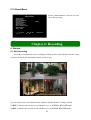
5.10 Reset Menu
Selecting “RESET MENU” will restore all to the
factory default settings.
MAIN MENU
CAMERA SETUP
RECORD SETUP
RECORD FRAMERATE
VIDEO QUALITY
RECORD SCHEDULE
SENSOR SETUP
HARD DRIVE SETUP
MISCELLANEOUS SETUP
NETWORK SETUP
RESET MENU
(
)MOVE
NORMAL
(SEL)SELECT
(MENU) EXIT
Chapter 6: Recording
6. Record
6.1 Start Recording
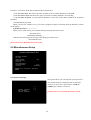
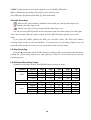
Press [●] record button to start recording according to the record schedule you have setup.
System will display the information below on the screen.
[●]: the red dot next to the channel name indicates that the channel is being recorded.
[A-REC]: indicates the current record schedule is set as NORMAL-RECORD mode.
[S-REC]: indicates the current record schedule is set as SENSOR-RECORD mode.
17
[N-REC]: indicates the current record schedule is set as NO-RECORD mode.
[39%]: indicates the percentage of hard drive space currently used.
[M]: HDD info ([M] Master Hard Disk; [S] Slave Hard Disk)
6.2Audio Recording
[
]: indicates this video channel is bundled with an audio port, and the audio input is on.
[ ]: indicates the audio input is off.
[
]: indicates the audio is being recorded and the audio input is on.
You can press the [MUTE] button on the front panel to mute the audio output. The audio input
can be still recorded while the output is muted. Press the [MUTE] button again to preview the
audio.
If you press the[●REC]button the DVR goes into REC mode. The DVR will continue
recording based on the set ‘Record Schedule’. In record mode you can change channel view and
switch the audio channel. However you can not playback while in record mode.
6.3 Stop Recording
Press the [■] stop button and the DVR will stop recording. If the password protection function is
enabled the system will prompt you to input password. Only the correct password can stop the
recording process.
6.4 Estimated Recording Length
Estimated record time based on 160GB HDD using 9 cameras in Hours
Standard
NTSC
Standard
PAL
Quality
Highest
High
Normal
Lower
60fps
27
39
47
53
48fps
34
49
59
66
32fps
51
73
89
100
16fps
103
146
178
200
1fps
1653
2346
2853
3200
Quality
Highest
High
Normal
Lower
50fps
28
40
49
54
36fps
39
55
68
76
24fps
59
83
102
114
12fps
118
166
203
228
1fps
1422
2000
2444
2733
18
Chapter 7: Playback
7. Playback
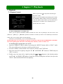
7.1 Playback Control
SEARCH VIDEO
DISK:MASTER
08/09/19
SLAVE[NONE]
11:16:31 -08//09/19 15:05:48
TYPE:EVENT
TIME
PLAY:2008/09/19
(
(
15:07:43
When you press the [ PLAY] button the DVR goes
into PLAY mode.
When you press the MENU button during PLAY mode
the SEARCH VIDEO window will open as illustrated
on the left. While in this window you can either choose
and playback a recorded event or manually input a
specific time to be viewed.
) MOVE (SEL)SELECT
) PLAY
(MENU)PREV MENU
To choose and playback a recorded event:
When you first open the SEARCH VIDEO window the arrow will be pointing at the most recent event
(0002).Use [▲UP]or [▼DOWN]buttons to find the event that you want to view and then press the PLAY
button. The event you have chosen will start playing.
2007/09/19=year/month/day 15:05:43=hour/minute/second
[NOTE] When the arrow is pointing at a specific event the date and time below HARD DRIVE: MASTER
shows the beginning (date and time) to the ending (date and time) of that recorded event.
To manually input a specific time to be viewed:
1. Open the SEARCH VIDEO window by pressing the “MENU” button while in “PLAY” mode.
The arrow will be next to the most recently recorded event.
2. Press the “MENU” button and the arrow will move below to the TYPE field.
3. Move the arrow left or right by using the UP “▲” and DOWN “▼” buttons to TIME and press
“SEL” to enter it.
4. Finally, move the arrow left or right by using the [
and
] buttons to the desired position
and UP “▲” and DOWN “▼”buttons to input the desired starting date and time, then press the
“PLAY” button and the DVR will start playing.
19
Chapter 8: USB Programming
8. USB Programming
8.1 Install
1. Place the USB Driver Program CD into your CD ROM.
2. If your CD ROM does not auto-run the install CD go to “My Computer”, select your CD drive, and click
on “PCVIEWER.EXE”.
3. Follow the prompts on your PC to finish the installation.
8.2 Program Interface
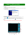
System will detect the HDD automatically when you connect the USB cable to your PC.
An USB icon“ ” will appear in the system tray (right bottom corner of the screen).
After you’ve seen the USB icon, double click “
” icon on your desktop to run the
program.
[Note] if you do not follow above steps the program will fail to detect HDD.
20
1.PTZ Control
12.Back one frame
2.Zoom in, Zoom Out
13. Record
3.HDD Play Mode
14.stop
4.File Play Mode
15. pause
5.Net Play Mode
16. Play
6.Event List
17.fast forward
7.Control Panel
18.forward one frame
8. Remote DVR Control
19.Playback Slider
9.Change Storage Device
20.Audio Slider
10.Capture Image
21.Software Version
11 .Backup Record
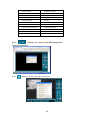
Press
(button 5) to connect to the DVR through the
Network or Internet.
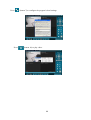
Press
(button 6) to open the video event lists.
21
Press
Press
(button 7) to configure the program’s local settings.
(button 16) to play video.
22
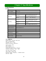
Chapter 9: Specifications
9. Specifications
9.1 DVR
Items
Descriptions
Video Standard
NTSC, PAL
Video Input/Output
9 Channels BNC/1 Channel BNC, 1 Channel VGA
Audio Input/Output
1 Channel/1 Channel
Resolution
NTSC:720X480@30fps (Each Ch)
PAL:720X576@25fps (Each Ch)
Features
Full-D1,1-CH/9-CH Display
Resolution
NTSC:720X240@60fps (9Ch.Total)
PAL:720X288@50fps (9Ch.Total)
Features
Variable Frame Rate/Variable QL per
Channel
Quality
4-Level (Highest High Normal low)
Monitoring
Recording
Audio
ADPCM2 CODEC
Video
MPEG4
Motion Detection
Settable Window/Level
Microprocessor
32-bit RISC Processor
Network Interface
TCP/IP (RJ45)
Network Monitor
IE (Internet Explorer), PC Viewer Software
PTZ Interface
RS485
USB Interface
USB2.0
VGA Output
Yes
Remote control
IR remote control
Power supply
DC 12V/3A
9.2 CAMERAS
Image Sensor: 1/4” Sony Color CCD
LED: 12 Infrared LEDs
Resolution: 420 TV Lines
Minimum luminance: 0.8Lux/F1.2
Signal System: NTSC
Lens: 3.6/6mm
Power Supply: DC12V
Dimensions: 68(w) x 68(d) x 92(h)mm
Operating Temperature: -20C - +50C
Auto Gain Control: On/Off
Video Output: 1.0Vp-p 75Ω
Electronic Shutter: 1/50(1/60) – 1/100,000 second
S/N ratio: >48dB
23
Appendix
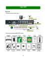
Appendix
1) System connect sketch map
2) Accessories Included With DVR Combo
24
Q-SEE Product Warranty
Thank you for choosing our products.
All of our product users have a conditional free warranty repair service for hardware
within 12 months starting from purchase date, and a free exchange service within one
month (valid for manufacturing defects). Permanent upgrading service is provided for the
software.
Liability Exclusions:
Any product malfunction, abnormalities in operation or damage caused by following
reasons are not within the free service scope of our company. Please select payable
service.
(1) Equipment damage caused by improper operation
(2) Improper environment and conditions in/on which the equipment operates, e.g.,
improper power, environment temperature, humidity and lightening strike etc. that cause
equipment damage.
(3) Damage caused by acts of nature: earthquake and fire etc.
(4) Equipment damage caused by the maintenance of personnel not authorized by our
company.
(5) Product sold over 12 months ago.
In order to provide various services to you, please complete registration procedure
after you purchase the product. Cut off or copy User’s Information Card and fax or mail it to
us after the card is filled in. You can also register the product by going to the
www.q-see.com website and clicking on the Register link.
If you have questions:
Contact Us:
Mailing Address:
Customer Service:
DPS Inc.
Phone: 877-998-3440 x 538
8015 E. Crystal Dr
Email: [email protected]
Anaheim, CA 92807
Website:
Tech Support:
http://www.q-see.com
Phone: 877-998-3440 x 539
Fax:
Email: [email protected]
714-998-3509
25
Customer Information Card
User’s Name
Mr./Mrs.
Company
Name
Postal
Address
Postal code
Phone
Number
E-mail
Model Number
of
Product
Serial Number
of
Product
Purchase Date
Distributor
The material in this document is the intellectual property of our company.
No part of this manual may be reproduced, copied, translated, transmitted, or published in any form
or by any means without our company’s prior written permission.
1. Our products are under continual improvement and we reserve the right to make changes without
notice, so no guarantee is given as to the correctness of its contents.
2. We do not accept any responsibility for any harm caused by using our product.
3. The product picture may differ from the actual product, which is only for your reference. The
accessories will probably be different according to the different selling areas. For details of accessories,
please refer to your local distributor.
Copyright reserved
26