1
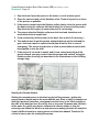
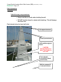
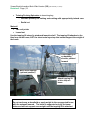
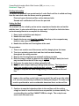
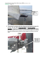
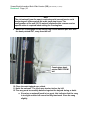
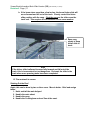
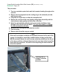
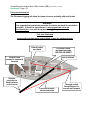
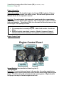
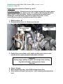
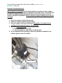
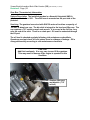
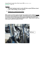
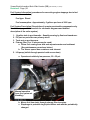
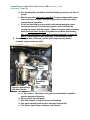
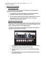
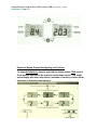
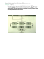
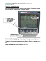
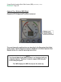
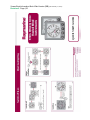
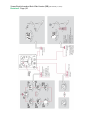
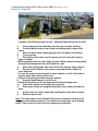
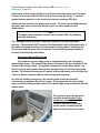
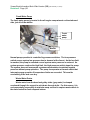
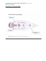
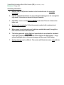
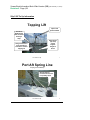
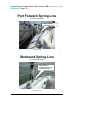
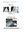
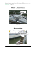
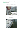
Parklawn Sailing Association, Inc. P.O. Box 9135 Gaithersburg, MD 20898-9135 Vivace Boat Information Book (BIB) Web Version Revision 6 (February 13, 2014) DISCLAIMER: Boat information contained in this Parklawn Sailing Association BIB is intended for the study use of members of the Association, only. This is not an operator's manual in the usual commercial sense. The boat study information is prepared by volunteer members who are not necessarily subject matter experts. The information may not be current and may contain errors. The boats are occasionally modified and updating of the study information may be delayed due to the voluntary nature of our club operations. Users are cautioned to refer to manuals aboard the boats or to contact the respective boat bosun for current information. 1. Tech Data/Specifications—p. 2 2. Flotation and PFDs—p. 6 15. LPG Stove Procedures—p. 63 3. Sails—p. 10 16. Freshwater System—p. 65 4. Reefing—p. 14 17. Deck Fittings for tanks—p. 67 5. Preventer Diagram—p. 19 18. Anchoring—p. 68 6. Engine—p. 20 19. Slip C-22 Tie Up—p. 69 7. Gearbox (Transmission)—p. 23 8. Fuel System—p. 25 The following items are in the on board BIB, but are not included in the on line version: 9. Through Hull Diagram—p. 40 20. Permanent Maintenance Log 10. Electrical—p. 41 21. USCG accident report form blank 11. VHF Radio—p. 46 12. Instruments—p. 49 Back Cover—NOAA Chesapeake Bay Forecast Zone Map 13. Head and Holding Tank—p. 59 14. Bilge Pumps—p.61 Index on last page Vivace Boat Information Book Web Version (BIB) (Rev February 13, 2014) Revision 6 Page | 2 Technical Data and Specifications Information Vessel: VIVACE Displacement: Ballast: Hull Construction: 8,200 LBS. 3,500 LBS. Fiberglass laminate with balsa core White with green & blue trim Yanmar 2GM 13 HP Diesel Hull Color: Engine Make And Model: Engine Serial Number: Engine Hours: Designer: Builder: Hull Number: Year Built: Model Year: 1984 Sail Number: Registration Number: Dimensions Prop Gearbox Stuffing box VHF Radio VHF Radio remote MMSI TYPE: 30' Express 30 Sloop 6 keel bolts Continuous rating 13 hp @ 3400 rpm 11303 N/A Steve Killing Express Yachting, Midland, Ontario, Canada ZYE30070F484 Jun-84 63230 MD 9778 AR LOA 30' 2-blade, fixed pitch urethane 14-inch (diameter) x 11 (pitch) LWL 24' 6" Beam 10' Draft 5' 6" Performance Propellers, LLC, Homer, NY http://mysite.verizon.net/resqp86c/performancepropellers/ Shaft diameter: 1" and tapered down from that to a 3/4" thread, with a 1/4" keyway. Kawzaki SN 19393 Use SAE 30W motor oil. Kokyukoki KM2Filler is 7/8” hex head. A gearbox with Dipstick is scored and marked a ratio of 26.1; at .25 liter (full) line Dripless Uniden UM 525 SN 601A 74000 797 Uniden WHAMx4BK 338086035 Vivace Boat Information Book Web Version (BIB) (Rev February 13, 2014) Revision 6 Page | 3 Instruments Wind Depth/Speed Voltage Compass Clinometers Bilge pump Engine oil filter Engine drive belts Engine drive belts Fuel filter Racor/Parker 120RMAM Secondary Fuel filter element (3 micron) Fuel tank Marine Toilet Holding tank Fresh water tank Fresh water pump RaymarineST60+ Wind &Close Hauled Wind Instrument Raymarine ST-40 Nexus Silva 5 ½” diameter Aquameter Galaxy 2-scale heel (roll) angle mounted on port cabin Single scale pitch angle clinometer mounted one on each side of the companionway hatch Rule RM-1100 12v, 5.0 amp; outlet 1 1/8 inch OD requires 1 1/8 inch ID hose Currently installed: Yanmar 12915035153; (obsolete model number 12915035152) Alternator Vbelt: PN25132003000 Water pump belt: PN10451178780 Racor/Parker R12T 10 micron solid state switch; 5 amp fuse Oil - (2) Quarts 10W-30 Oil or 15W40; SERVICE: SAE CB or CC moderate diesel service We have spare on board We have spare on board PN 10450055710; 14 gal (per Karl's Marine Engine Services survey report July 2, 2007) Raritan PH-II 20 gal. Plastimo bladder, 26.4 gal. Shurflo 2088403-444, standard pump; 1990 manufacture Dimensions: H= 24"; W= 14"; L= 12" Filler is on starboard side near primary winch Diaphragm demand, rundry, 10.6 liter/min; 12 VDC; 4 amps; open flow 2.8 GPM Output as installed approx. 600 GPH Rule model 35A bilge pump redundant float switch Note the crankcase capacity is specified as 2.0 Liters (1 Liter = 1.05 quarts). The oil filter also has some volume that needs to be filled that is not included in the crankcase capacity. Vivace Boat Information Book Web Version (BIB) (Rev February 13, 2014) Revision 6 Page | 4 Raw Water pump YAN72157542702 Raw Water impeller Yanmar PN: 104211-42071 Raw water strainer Groco Strainer 255-D; Type SA/SD Type 8A24 SLAB AGM (West Marine) Isomat NG-46 Mast SN:70665 Batteries (2) Mast Unknown after market pump is now installed Non-serviceable Height: Top of cabin to top of mast--41.5 ft. (Based on http://mauriprosailing.com/ techinfo/boatspecs/Rig%20 E.htm) Chain plates anodized aluminum Rod Rigging Navtec Boom Isomat NB-26 Boom Section Genoa T track 1-inch Slotted headstay and feeder Stove/Oven Tuff-Luff 1205 Luff Tape #5 (4mm) .159" OD. Red stitching. Optimus International Harken HAR D172 Small Boat Traveler Car Hi Load / Pivoting Shackle with Ears Cabin top Barient #18 P.S. No. 349 Boom Kicker Rope clutches model 100-90 (obsolete) Spinlock tube PN ST-0.750-37.3 Hatch, forward Bomar Low Profile extruded hatch Edson wheel 36' BOM-N107010A Traveler car Winches Steering Measurements (OD): 4" x 3 1/2" (100mm x 90mm) Amp/Hr: 79; C.C.A.: 525; MCA 735 anodized aluminum Wall Thickness: .092" Propane 37 mbar; 442 g/h Length: 2 7/8"; Width: 2 3/16"; Number of Balls: 42; Max Load: 850LB; Breaking strength: 2500LB Primary Barient #25; 40:1 Per http://www.sailnet.com/foru ms/gearmaintenance/31617primary-winches-barientvs-lewmar.html Emergency tiller Dimensions: Base 6.5"; capstan 3.5"; H 6.5" Gasket: P200025-10 internal halyards Weight/ft.: 1.76 lbs. Weight/M: 2.63 kg Vivace Boat Information Book Web Version (BIB) (Rev February 13, 2014) Revision 6 Page | 5 Anchor Danforth 12 lbs. 200’ rode Anchor (lunch hook) Danforth 5 lbs. Port lazarette chain ground tackle Vivace Boat Information Book Web Version (BIB) (Rev February 13, 2014) Revision 6 Page | 6 Flotation and PFDs Information 1. Personal Flotation Devices. The boat is equipped with 8 PFDs. All are stowed in rack at the back of the marine toilet compartment. 2. Flotation Cushions. The boat is equipped with 4 flotation cushions. All are stowed in recess at the aft end of the port settee. 3. Cockpit Throwable MOB Flotation. One of the flotation cushions must be hung on the stern rail while underway. (See illustration below.) a. See the illustration on the following page for correct attachment. b. Best practice is to ALWAYS attach the MOB buoy light lanyard to the cushion. The attachment must be made outside the stern rail. c. If the cushion is not secured as shown, it will be blown overboard in high wind. 4. For Night Crew Overboard/Man Overboard (MOB) (See illustration below.) a. The orange NAVIMO Life Buoy light (gravity activated) is stowed in a bracket on the stern rail. b. Before night sailing, attach the lanyard to the MOB flotation cushion. Best practice: ALWAYS attach the lanyard (outside the stern rail.) c. The light will float upright and illuminate when it enters the water. d. This will allow the crew to maintain visual contact with the vicinity of the MOB and will help the MOB find the flotation cushion. e. Recovery of the light and cushion is secondary to crew recovery. It should be regarded as expendable during MOB recovery. Vivace Boat Information Book Web Version (BIB) (Rev February 13, 2014) Revision 6 Page | 7 Cockpit Throwable Cushion and MOB Buoy Light Mounting Wrap strap twice to keep wind load OFF Velcro MOB buoy light lanyard OUTSIDE stern rail 5. 2 Velcro straps required for high wind LifeSling Flotation Collar (a) (b) (c) Attached to the port stern rail. 125 foot multifilament floating polypropylene line Equipped with light to ensure visibility in the dark. LifeSling Procedures WARNING It may be difficult or impossible to don the LifeSling while wearing a PFD. If the LifeSling must be used to lift a person from the water, it may be necessary to discard the PFD to don the LifeSling collar (a) The LifeSling storage bag is stenciled with operating instructions. (b) Vivace’s boom vang is equipped with quick release shackles on both ends. Use it as a block and tackle on a halyard to lift the LifeSling victim aboard. (c) See procedures below for a complete description of LifeSling recovery. Vivace Boat Information Book Web Version (BIB) (Rev February 13, 2014) Revision 6 Page | 8 1. Stop the boat if near the person in the water, or circle at slow speed. 2. Open the case and pull out the flotation collar. Throw it beyond or as close to the person as possible. 3. If the person cannot reach the flotation collar, slowly circle the person with the boat, towing the collar so that the floating line is moved to the person. Stop the boat and engine (to ensure the prop is not turning). 4. The person slips the flotation collar over the head and shoulders and around the chest at armpit level. 5. Crew on the boat pull the person to the boat. (Use a winch if necessary.) 6. The method used to get the person onboard depends on the boat and its gear—the boat owner or captain should plan ahead for this in case of emergency. The person may be able to climb a swim ladder or assist with being pulled in over the side. 7. If the person is too weak to assist, and if crew cannot manually pull the person aboard, you may need to hoist the person with a winch, using the flotation collar as a sling (as described in the illustrations on the LifeSling storage bag.) Hoisting the Person Aboard Getting the rescued person to the boat is only half the process—getting the person back on board may be the most difficult part. Even in ideal circumstances with light wind and calm seas, most people are too heavy to be lifted straight up the side of the boat and over the rail by one or two crew. Someone who has been in the water for a while may be too exhausted to climb a ladder or help the rescuing crew. When the wind is up and waves are making the boat roll and pitch, it can be difficult even for a strong person to climb back aboard. Therefore it’s critical to have a plan for hoisting the person. Vivace Boat Information Book Web Version (BIB) (Rev February 13, 2014) Revision 6 Page | 9 1. Use the boom vang as a block and tackle attached to a halyard. The main halyard is the best choice because it runs cleanly to the stern. The starboard jib halyard is generally not in use and is an acceptable choice if time is urgent. The boom is a poor choice for attaching the block and tackle because it does not provide enough height to raise the person completely over the side. 2. Hoist the top block at least 10 feet above the deck. 3. Winch in the block-and-tackle fall line to raise the person up over the rail. The key thing is to have a plan before the emergency strikes. Vivace Boat Information Book Web Version (BIB) (Rev February 13, 2014) Revision 6 Page | 10 Sails Information Headsails Tuffluff forestay slot precautions: Always use the pre-feeder when hoisting foresail. DO NOT load the foresail or sheets while hoisting. This will damage the slot or sail Final checks before for head sail hoist: Jib halyard attached Luff bead in foil slot Luff bead through prefeeder. CAUTION Sail may be torn on hoist if pre-feeder is not used. Tack shackle connected at deck (not shown) Sail ties removed if in use (not shown) Vivace Boat Information Book Web Version (BIB) (Rev February 13, 2014) Revision 6 Page | 11 #1 155% Racing Genoa. Fusion X Aramid. This is a low stretch racing sail, intended primarily for racing. It is available for use by all members. WIND SPEED LIMIT: 15 knots true, 22 knots apparent wind speed. Use outboard, aft jib track. #1 155% Racing Light Air Genoa. One piece Aramid. This is a low stretch racing sail, intended primarily for racing. It is available for use by all members IN LIGHT AIR. WIND SPEED LIMIT: 10 knots true, 16 knots apparent wind speed. Use outboard, aft jib track. #2 140% Cruising/Racing Genoa. Dacron Cross Cut (high modulus material) This is a relatively low stretch dual purpose sail. It is the primary cruising genoa. WIND SPEED LIMIT: 21 knots true, 28 knots apparent wind speed. Use outboard, aft jib track. #3 110% Cruising/Racing jib. Dacron WIND SPEED LIMIT: Not determined. Has been demonstrated to 30 knots. Use inboard, forward jib track. Rig sheets INSIDE shrouds. Storm Jib None aboard. Repair or replacement in progress. Spinnakers Racing Spinnaker in rectangular bag o Intended primarily for racing o Radial cut Vivace Boat Information Book Web Version (BIB) (Rev February 13, 2014) Revision 6 Page | 12 Training/Cruising Spinnaker in drawstring bag o Intended primarily for training and cruising with appropriately trained crew o Radial cut Mainsail Two reef points Loose foot Use the topping lift stored in starboard lazarette shelf. The topping lift attaches to the blue loop on the boom, NOT the sheet metal eye strap that cannot support the weight of the boom. Hook topping lift on backstay shackle, pointed forward Main sheet stowage (optional position) Attach topping lift to blue loop on boom WARNING Do not use boom as handhold or apply weight to the unsupported boom with the mainsail lowered. The boom is supported only by the boom kicker and will not support crew weight until the topping lift is attached. Vivace Boat Information Book Web Version (BIB) (Rev February 13, 2014) Revision 6 Page | 13 Note Keep some tension on the boom vang to prevent separation of boom kicker from the boom. If a gust lifts the boom with no tension on the vang, the kicker slide on the boom can move full travel OFF the end of the track and the kicker will separate from the boom. See “Reefing” section below for illustration. Battens--Operating instructions for the Quantum Sails RBS Rocket Pocket batten insertion and adjustment are contained in the black Systems User Manuals binder. Vivace Boat Information Book Web Version (BIB) (Rev February 13, 2014) Revision 6 Page | 14 Reefing Information The boom and mainsail have provisions for 2 reefs. Each reef line is coiled and hung from the cam cleat under the boom near the gooseneck. First reef--green flecked reef line on the starboard side Second reef--red flecked reef line on the port side Setting the Reef The mainsail can be reefed by as few as two experienced hands who are familiar with the boat. It gets easier with three or more and it is helpful to divide the labor and make assignments to accomplish the following: 1. Ease, hoist and tail the main halyard. 2. Handle the main sheet. 3. Handle the boom vang from the cockpit. (Standing on the companionway ladder to stay clear of other crew.) 4. Handle the reef line and Cunningham at the mast. The procedure: 1. There is no need to uncoil the excess reef line hanging from the boom. 2. Turn to or maintain upwind tack and then hold constant heading throughout the reefing exercise. 3. Remove the Cunningham from mainsail and hang on mast. 4. Relax the vang to allow the boom to rise slightly during re-hoist (the leech may tension before the luff if the vang is tight). 5. Fully ease the main sheet to allow mainsail to luff. 6. Ease the main halyard and begin taking in the reef line. The halyard and mast crew members must coordinate their actions. Ease the halyard enough to keep the luff slack during reefing to reduce loads on the reef line. Note Loads on the reef line can be high in strong wind if the sail is not fully luffed or if crew are not perfectly coordinated in easing the halyard. The mast crew must be positioned to exert considerable downward force on the reef line. 7. Continue to ease the halyard and take in the reef line until the reefing cringle on leech is as close to the boom as possible (as shown below). The crew handling the reef line CANNOT SEE the cringle. The cockpit crew must coach the mast crew. Vivace Boat Information Book Web Version (BIB) (Rev February 13, 2014) Revision 6 Page | 15 Reefing cringle fully down. 8. To set the reef, manually rotate the reefing cam cleat forward to engage the reef line. The cam cleat is not spring-loaded and must be engaged manually. To engage the cam pull the line aft along the bottom of the boom and release tension. OR, rotate the cleat down (forward) against the reefing line while holding tension on the line, then release line tension to lock the cleat. Manually operated cam cleat Vivace Boat Information Book Web Version (BIB) (Rev February 13, 2014) Revision 6 Page | 16 Note The old mainsail (now the spare) required special precautions to avoid tensioning sail slides against the mast track stop screw. The configuration of the new (2013) mainsail eliminates this concern and no special action is required when setting the Cunningham. 9. Attach the Cunningham to the reefing ring on the mainsail port side with the hook pointed OUT, away from the sail. Cunningham hook points AWAY FROM sail. 10. Close the main halyard rope clutch. 11. Hoist the mainsail. The leech may tension before the luff. 12. The vang must be carefully balanced against the halyard during re-hoist. a. If tension on mainsail leech is too great, this indicates that the vang is too tight and the luff cannot be fully tensioned. Ease the vang slightly. Vivace Boat Information Book Web Version (BIB) (Rev February 13, 2014) Revision 6 Page | 17 b. If the boom rises more than a few inches, the boom kicker slide will move forward and fall out of the track. Closely control the kicker slide position with the vang. Cleat the vang as the slide nears the track end. This requires the full attention of one crew member. Ease vang slowly to keep kicker slide in track. Note If the kicker slide is allowed to move fully forward and fall out of the track, this is inconvenient but not dangerous. Re-insert the slide in the track when more pressing tasks have been completed. 13. Trim mainsail to course. Shaking Out the Reef Again, this can be done by two or three crew. More is better. Brief and assign tasks: 1. Hoist and tail the main halyard. 2. Handle the main sheet. 3. Handle the vang. 4. Handle the Cunningham and reef line at the mast. Vivace Boat Information Book Web Version (BIB) (Rev February 13, 2014) Revision 6 Page | 18 The procedure: 1. Turn to or maintain upwind tack and hold constant heading throughout the exercise. 2. Remove the Cunningham from the reefing ring on the mainsail port side and hang on mast. 3. Fully ease the main sheet to allow the mainsail to luff. 4. Release the reef line at the cam cleat by pulling down forcefully until the cleat releases under gravity and falls clear of the line. 5. Hoist the mainsail fully while the mast crew member facilitates clean feeding of the reef line into the boom. The cam cleat tends to re-engage the line and stop the sail hoist. 6. Re-attach the Cunningham and adjust as needed. 7. Trim to course. 8. Remove slack from the vang as needed. Note If the reef is not shaken out before the mainsail is lowered at the end of the voyage, it is helpful to correct this condition before closing out the boat. With the mainsail flaked, the reef lines can easily be pulled from the aft end of the boom until the coiled reef lines touch the cam cleat at the base of the boom near the gooseneck. Do this to avoid surprising the next crew that raises the mainsail. Reefing lines in stowed, unreefed position. Vivace Boat Information Book Web Version (BIB) (Rev February 13, 2014) Revision 6 Page | 19 Preventer Information The illustrated rigging will allow the boom to move vertically with wind loads. WARNING It is important to tension the preventer to remove as much line stretch as possible. If stretch is not removed, a strong gust can cause an accidental jibe, even with the preventer rigged. Port tack illustrated (reverse all gear and move snatch block to port for starboard tack.) Cleat at cabin top winch Snatch block stowed in starboard lazarette Preventer inside windward shrouds, BELOW JIB SHEET Red Preventer Boom Shackle preventer to fixed bail near end of boom Preventer outside leeward shrouds BELOW JIB SHEET Through snatch block attached to toe rail well forward Vivace Boat Information Book Web Version (BIB) (Rev February 13, 2014) Revision 6 Page | 20 Engine Information System Description The installed engine is a Yanmar 2GM, 2 cylinder, 15 horse power diesel. It is raw water (sea water) cooled. See the black Systems Users Manuals binder for the operator’s manual. Servicing The cooling water inlet seacock is located under the companionway ladder to port and is marked with a placard. The cooling water strainer is located in the port lazarette. The yellow oil filler is in the center of the valve cover on top of the engine. Oil capacity is 2 liters. Notes 1. Oil consumption is normally very low. Add oil with caution. Avoid over filling. 2. Diesel oil quickly turns black in service. Black oil is normal. Gray oil indicates water in the crankcase and requires immediate investigation. Engine Control Panel Engine Control Panel 4 lamps on left are not used Coolant Hot lamp illuminates on test, but is not used on 2GM engine Low oil pressure (alarm sounds) Batteries not charging System power switch Fuel cut off (Engine Stop) Starter switch Lamp test switch Normal Starting (see checklist in Vivace Log, tab 3) Under Sail To prevent abnormal wear in the gear box, the engine manufacturer (Yanmar) requires that the gear shift be left in neutral when sailing without engine power. This allows the prop to freewheel in the passing water. Slight vibration and prop noise may be heard throughout the boat. Vivace Boat Information Book Web Version (BIB) (Rev February 13, 2014) Revision 6 Page | 21 Engine Stop (see checklist in Vivace Log, tab 3) Low Battery Starting If batteries are at a low charge state and the engine cannot be started with the battery switch in the “All” position, the following procedure may be used to start the engine. Before concluding that the batteries are discharged, check the battery terminals for tight connections. Loose connections can produce low battery output to the starter. 1. Battery switch—All 2. Decompression levers (2)—Both open (fully aft) Decompression lever Decompression lever 3. Position one crew member at the engine control panel and one crew member at the engine (companionway ladder removed) WARNING Turning engine pulleys and belts can entangle loose clothing, long hair and jewelry, causing serious injury. Stay clear. 4. Starter—Engage 5. When engine is turning—close ONE decompression lever 6. When engine is firing on one cylinder—close remaining decompression lever Vivace Boat Information Book Web Version (BIB) (Rev February 13, 2014) Revision 6 Page | 22 Extended Cranking Required If the engine does not start and extended cranking is required, serious engine damage can occur. If the engine is cranked for more than about 15 seconds with no start, the exhaust system will fill with water that will then back up into the exhaust manifold and cylinders. Before extended engine cranking (more than 20 seconds): 1. Close the engine cooling inlet seacock. 2. Continue cranking until the engine starts. 3. Open the engine cooling inlet seacock. Remember, the engine has no cooling until the seacock is open. Do not delay. 4. To avoid overheat damage to the electric starter: a. limit cranking to 15 seconds b. cool starter 60 seconds, before cranking again 5. If it is suspected that a quantity of water may have accumulated in the exhaust system, drain the muffler. Muffler drain Vivace Boat Information Book Web Version (BIB) (Rev February 13, 2014) Revision 6 Page | 23 Gear Box (Transmission) Information System Description The installed gearbox is a Kawzaki Kokyukoki KM2-A gearbox with a ratio of 26.1. The shift lever is mounted on the port side of the pedestal. Servicing The gearbox is serviced with SAE 30 motor oil and has a capacity of .25 liter, or about one cup. The dip stick is integral to the hex-head filler cap. The cap requires a 7/8” socket or open end wrench. It is scored at the full line, very near the end of the stick. There is no drain port. Oil must be extracted through the fill port. The oil level is checked regularly following club maintenance checklists. Operators need not check oil level unless there is evidence of leakage. Oil is changed biennially according to club maintenance checklists. CAUTION Add fluid cautiously. It is very easy to over fill the gearbox. This may result in damage if the engine is operated in this condition. Gearbox filler port cap/dipstick (7/8” socket) Vivace Boat Information Book Web Version (BIB) (Rev February 13, 2014) Revision 6 Page | 24 Operation 1. Shift ONLY while the throttle is at idle AND after engine RPM have slowed to idle. Rapid shifting can cause damage. 2. Always pause in neutral when shifting. While under way with the engine stopped, the gearbox must be shifted to neutral to allow the prop to windmill in the water. This reduces boat speed slightly, but is necessary to avoid clutch damage from high forces applied to the clutch if the prop is locked in gear while passing through the water. Slight vibration and prop noise may be present throughout the boat. Shift lever Vivace Boat Information Book Web Version (BIB) (Rev February 13, 2014) Revision 6 Page | 25 Fuel System Information (procedures for correcting engine stoppage due to fuel contamination are below) Fuel type: Diesel Fuel consumption: Approximately .5 gallons per hour at 3000 rpm Fuel System Description (Description of operator serviceable components only. See the last pages of this section for schematic diagrams and detailed description of the entire system) 1. 2. 3. 4. 14 gallon tank in port lazarette. Quantity sensing by float and transducer. Fill port on port side near primary winch Tank vent on port transom. Primary filter (3 or 10 micron may be used) a. Filters fuel coming from tank and separates water and sediment. (See maintenance procedures below.) b. The Vivace spares box contains a new element. 5. Lift pump (visible through quarter berth access door) a. Operates at relatively low pressure, 25—35 psi. Lift Pump Manual operation lever (for system air bleeding) b. Moves fuel from tank, through primary filter to engine. c. Diaphragm is potential single point failure and must be periodically changed. Vivace Boat Information Book Web Version (BIB) (Rev February 13, 2014) Revision 6 Page | 26 d. Can be manually operated for fuel line bleeding (use lever on side of pump). e. Manual operation may not be possible if engine stopped with pump cam at extreme of travel—turn the engine over to reset the cam to restore manual operation. f. If fuel line bleeding is unsuccessful with manual pumping, more forceful movement of fuel through system can be achieved by turning the engine with the starter. (Observe engine starter cranking limits to avoid water flooding of cylinders and starter overheating. See engine procedures “Extended Cranking Required” on page 22, above.) Protect against fuel spray/spill if this method is used. 6. Secondary fuel filter (2 micron) (visible with companionway ladder removed, engine starboard side) Bleed nipple Secondary filter Injection pump banjo bolt bleed nipple a. Is “last chance” filter before fuel goes to contamination sensitive injector pump and injectors. b. Receives fuel from lift pump. c. Has bleed nipple on top for system air bleeding. d. Has paper cartridge that must be changed periodically. e. The Vivace spares box contains a new element. Vivace Boat Information Book Web Version (BIB) (Rev February 13, 2014) Revision 6 Page | 27 Fuel System Operating Notes Fuel system Contamination and Air Bleeding Contamination of fuel is the most likely cause of engine stoppage. If either filter is full of sediment, fuel will not pass through. To check and rectify this problem: 1. Follow primary filter sediment chamber draining procedure (below) carefully to minimize introduction of air into fuel lines. 2. For serious contamination, replace primary filter element with spare from spares box (see procedures below.) 3. Opening any part of the fuel system will introduce air that will interrupt fuel flow and cause engine stoppage. 4. When opening any part of the fuel system, be ready with drip containers and absorbent material to prevent fuel contamination of bilge that will be pumped overboard. A drip pan, waste fluids bottle and funnels are under the starboard settee. 5. Diesel fuel spilled on electrical wiring can soften insulation. 6. Only a case of extreme contamination would require replacement of the secondary filter. If necessary: a. Remove filter cover. b. Replace filter element with spare from spares box. 7. If it is necessary to bleed the fuel system, follow this sequence (sequence is in direction of fuel flow from lift pump to injection pump): a. Pressurize lines with manual lift pump lever (see photo above). Note During maintenance operations at the dock, the fuel lines can easily be pressurized for bleeding by pressurizing the fuel tank with a shop vac hose inserted in the fuel filler. If this method is used, place a cloth over the shop vac nozzle to prevent debris from being blown into the tank. b. Bleed secondary fuel filter nipple until fuel is free of bubbles. c. Bleed injection pump banjo bolt nipple until fuel is free of bubbles. (Usually not necessary.) (See photo above.) 8. Injectors should not require bleeding. If they do (indicated by engine will not start after bleeding low pressure lines): a. Open the throttle fully Vivace Boat Information Book Web Version (BIB) (Rev February 13, 2014) Revision 6 Page | 28 b. Slightly loosen the injector nut (one cylinder at a time.) Crank engine until no bubbles are visible (observe engine starter cranking limits to avoid water flooding of cylinders and starter overheating. See engine procedures “Extended Cranking Required” on page 22, above.) 9. After opening any part of the fuel system monitor carefully for leaks. 10. Do an immediate operational check. 11. During first hour of engine operation, check frequently. WARNING Keep hair and loose clothing clear of accessory drive belts on turning engine. Primary Fuel Filter Maintenance Procedures (these checklists are posted above the Primary filter) Primary fuel filter sediment draining procedure (Draining is periodically done by bosuns. For boat crew, this is a troubleshooting procedure in event of engine stoppage.) 1. Make sure engine is off and not hot. 2. Close shut-off valve between fuel tank and filter (top of fuel tank). 3. When opening any part of the fuel system, be ready with drip containers and absorbent material to prevent fuel contamination of bilge that will be pumped overboard. A drip pan, waste fluids bottle and funnels are under the starboard settee. 4. Open vent plug on mounting head with a 1/2" wrench (silver bolt on side of mounting head—see illustration below). 5. Remove sump drain valve cap (not shown in illustration.) 6. Open sump drain valve to drain contaminated fuel. Push the valve center button up to open. NOTE--Do not leave drain open for very long. It will drain the entire filter of all fuel and require extensive system air bleeding. Vivace Boat Information Book Web Version (BIB) (Rev February 13, 2014) Revision 6 Page | 29 7. Release valve to close. It is spring loaded to the closed position. Sump drain valve Vent plug Vent plug Note Sediment can interfere with closing of the sump drain. If the valve continues to drip fuel after the valve is released, quickly cycle the valve up and down to flush the sediment out of the valve seat. Repeat as necessary. Dripping fuel goes to the bilge and then to the bay. If drip cannot be stopped, tightly torque the sump drain valve cap and place a drip pan (under starboard settee) under the drain. Primary fuel filter sump drain valve bottom view. NOT SHOWN: Sump drain valve cap. Spring loaded closed. Lift to drain. Be prepared to catch fuel. Vivace Boat Information Book Web Version (BIB) (Rev February 13, 2014) Revision 6 Page | 30 8. Re-install sump drain valve cap. 9. Close vent plug and tighten snugly. 10. Fully open fuel shut-off valve. 11. Brief draining of the filter can be accomplished without losing prime through the filter. If a large quantity of fuel has been drained, leave the fuel valve closed and follow the Primary fuel filter priming procedure, below. Primary fuel filter change procedure (see exploded parts diagram below) 1. Make sure engine is off and cool to touch. 2. When opening any part of the fuel system, be ready with drip containers and absorbent material to prevent fuel contamination of bilge that will be pumped overboard. A drip pan, waste fluids bottle and funnels are under the starboard settee. 3. Close shut-off valve between fuel tank and filter (top of fuel tank). 4. Drain filter assembly of fuel. 5. Loosen head bolt with a 15/16" wrench. 6. Spin bowl and element (together) off of mounting head. 7. Spin collection bowl off and save. 8. Dispose of filter properly. 9. Lubricate new seals with motor oil or clean fuel and install only with new filter. 10. Install new O-ring onto collection bowl. 11. Install collection bowl onto new filter. 12. Install new gasket onto new filter. 13. Follow priming Instructions, below. Primary fuel filter priming procedure (see exploded parts diagram below) 1. Close shut-off valve between fuel tank and filter. 2. When opening any part of the fuel system, be ready with drip containers and absorbent material to prevent fuel contamination of bilge that will be pumped overboard. A drip pan, waste fluids bottle and funnels are under the starboard settee. 3. Open vent plug on mounting head with a 1/2" wrench (silver bolt on side of mounting head). 4. Slowly open shut-off valve until fuel begins to spill out of vent port. This may be slow—allow up to 2 minutes for fuel to appear. 5. Close and tighten vent plug. 6. Spin bowl and filter (together) onto mounting head tighten by hand - do not use tools. 7. Fully open fuel shut-off valve. 8. Bleeding of fuel system is not necessary if this procedure has been followed. 9. Start engine and check for leaks. Vivace Boat Information Book Web Version (BIB) (Rev February 13, 2014) Revision 6 Page | 31 Vivace Boat Information Book Web Version (BIB) (Rev February 13, 2014) Revision 6 Page | 32 Vivace Fuel System How Boat Things Work, by Charlie Wing, 2004, 2007 , published by lnternational Marine and McGraw Hill gives a clear and simple description of the Yanmar 2GM engine fuel system on Vivace. Only the fuel tank placement and primary filter design differ from the Vivace installation. Copyright protected material is in the BIB aboard the boat, but is omitted from web version of the BIB. Text continues on page 40. Vivace Boat Information Book Web Version (BIB) (Rev February 13, 2014) Revision 6 Page | 33 Copyright protected material is in the BIB aboard the boat, but is omitted from web version of the BIB. Text continues on page 40. Vivace Boat Information Book Web Version (BIB) (Rev February 13, 2014) Revision 6 Page | 34 Copyright protected material is in the BIB aboard the boat, but is omitted from web version of the BIB. Text continues on page 40. Vivace Boat Information Book Web Version (BIB) (Rev February 13, 2014) Revision 6 Page | 35 Copyright protected material is in the BIB aboard the boat, but is omitted from web version of the BIB. Text continues on page 40. Vivace Boat Information Book Web Version (BIB) (Rev February 13, 2014) Revision 6 Page | 36 Copyright protected material is in the BIB aboard the boat, but is omitted from web version of the BIB. Text continues on page 40. Vivace Boat Information Book Web Version (BIB) (Rev February 13, 2014) Revision 6 Page | 37 Copyright protected material is in the BIB aboard the boat, but is omitted from web version of the BIB. Text continues on page 40. Vivace Boat Information Book Web Version (BIB) (Rev February 13, 2014) Revision 6 Page | 38 Copyright protected material is in the BIB aboard the boat, but is omitted from web version of the BIB. Text continues on page 40. Vivace Boat Information Book Web Version (BIB) (Rev February 13, 2014) Revision 6 Page | 39 Copyright protected material is in the BIB aboard the boat, but is omitted from web version of the BIB. Text continues on page 40. Vivace Boat Information Book Web Version (BIB) (Rev February 13, 2014) Revision 6 Page | 40 Through Hulls Information Vivace Boat Information Book Web Version (BIB) (Rev February 13, 2014) Revision 6 Page | 41 Electrical System Information Power Supply Vivace has no shore power provisions. All electrical power is provided by the engine driven 12 volt alternator. Rectifiers integral to the alternator convert the alternating current produced by the alternator to 12 volt direct current used by the batteries. The batteries power all electrical components on the boat. System voltage can be displayed on the Nexus Multi instrument as described in the Instruments section, below. With the engine running (alternator turning), system voltage will be indicated at about 13.6--8 volts. With the engine stopped, battery voltage will vary from about 12.1 volts at near full charge to 11.5 volts after a typical house load over several hours. Engine starting has been demonstrated at 11 volts. Batteries Power is stored in two identical sealed lead-acid absorbed glass mat (SLAB AGM) batteries. These are dual purpose batteries providing desirable characteristics of both quick discharge for engine starting and long duration deep discharge for prolonged load. No user servicing is possible. These are considered to be very safe batteries with a design that practically eliminates the possibility of hydrogen explosion that can occur when wet cell batteries are mishandled. The batteries are located under the quarter berth. Vivace Boat Information Book Web Version (BIB) (Rev February 13, 2014) Revision 6 Page | 42 The capacity of each battery is: Amp/Hr: 79 Cold cranking amps (CCA): 525 Marine cranking amps (MCA): 735 The battery charge state can be monitored on the cockpit instruments as described in the Instruments Information portion of this manual. Battery Switch Caution Do not switch the battery switch to “OFF” while the engine is running. Switching the battery switch off while the engine is running can result in alternator damage. The batteries are controlled by the four-position, make-before-break Perko battery switch. The make-before-break feature protects the alternator from potentially damaging zero load operation during battery switching and ensures uninterrupted power to electronics that may reboot if power is interrupted. Switching the battery switch off while the engine is running can result in alternator damage. WHAM charger 12 volt power outlet Battery switch The “1” position selects the battery mounted in the inboard or port position. The “2” position selects the battery mounted in the outboard or starboard position. Only the battery or batteries selected on the battery switch are charged when the engine is running. When the battery switch is “OFF”, the alternator will not charge the batteries and the alternator may be damaged if the engine is running. Vivace Boat Information Book Web Version (BIB) (Rev February 13, 2014) Revision 6 Page | 43 Battery Management Caution Do not fully discharge batteries. The batteries must be operated and managed carefully to avoid damage that will result from deep or total discharge. The batteries are identical and interchangeable for operational purposes. To manage battery power and to avoid discharging both batteries below a level that will allow engine starting, the crew must adopt a battery management plan and follow it. A practical method is as follows. 1. Start the engine with the battery switch in the “ALL” position to maximize cranking power. The engine may also be started on a single battery. Leave the switch in the “ALL” position during engine operation to charge both batteries. 2. After engine stop, designate one battery as the “house” battery and move the battery switch to select the house battery only. A common practice is to designate the number one position as the house battery on odd numbered dates and the number two position as the house battery on even numbered dates. The unused battery is thus reserved, fully charged, for engine start. Alternating batteries daily ensures frequent cycling to prolong battery life. 3. When the engine is re-started, switch the battery switch to the “ALL” position to allow charging of both batteries. 4. When anchoring overnight, the house battery remains the house battery until the engine is started and recharging is complete. The charge state, not the calendar, determines when to switch house load from one battery to the other. Always keep one battery in a high charge state for engine starting. Notes 1. If the batteries are discharged so much that the engine will not turn over, the engine may be started using the method described in the “Low Battery Starting” procedure in the Engine Information portion of this manual. 2. Before concluding that the batteries are discharged, check the battery terminals for tight connections. Loose connections can produce low battery output to the starter. Vivace Boat Information Book Web Version (BIB) (Rev February 13, 2014) Revision 6 Page | 44 Electrical Power Distribution Fuse Protected Circuits Two components are wired directly to the batteries to allow operation regardless of battery switch position. 1. The bilge pump circuit is protected by a fuse mounted in the bilge pump switch panel. (See photo in Bilge Pumps section.) 2. The 12 volt power outlet socket (see photo of battery switch, above) is protected by an in-line fuse in the starboard side of the engine compartment, near the power socket. Circuit Breaker Protected Circuits With the exception of the fuse-protected circuits described above and the engine starter, all electrical components receive power through the circuit breaker (CB) panel just aft of the navigation table. Individual circuit breakers are identified by pictograms or text labels on the panel and provide power as follows: 1. Cabin lights CB—all cabin lights, v-berth lights, head sink light, vberth cabin fan, engine compartment dome light. 2. Running lights CB—bow and stern running lights and compass lighting. 3. Steaming light CB—forward-facing steaming light mounted near the center of the mast. Vivace Boat Information Book Web Version (BIB) (Rev February 13, 2014) Revision 6 Page | 45 4. Radio CB—VHF radio. 5. Instruments CB—ST-40 Bidata depth/speed system, ST-60+ wind system, all cockpit instruments, instrument lighting and binnacle GPS power cable. 6. Fan CB—quarter berth fan, only. V-berth fan is on the Cabin Lights CB. 7. Water CB—fresh water pump. 8. Propane CB—propane solenoid valve in transom port side propane locker. Vivace Boat Information Book Web Version (BIB) (Rev February 13, 2014) Revision 6 Page | 46 Radio Information The installed VHF radio is a Uniden UM 525. Operators manuals – see the black Systems User Manuals binder for operator’s manuals for the radio and the WHAM. WHAM (wireless remote control/microphone/speaker) This unit allows control of and use of the radio from any location on the boat. It is battery operated. Operating instructions (these are posted near the circuit breaker panel): (a) Keep Wham in charger (see photo of battery switch, above) and charger plugged in until Wham is needed in cockpit. This maximizes charge time. (b) Charging with engine not running is OK. (c) Unplug Wham charger before leaving boat. Emergency Operation Vivace’s Maritime Mobile Service Identity (MMSI) number 338086035 is loaded in the radio and will identify the boat to other boats and the U.S. Coast Guard if a digital MAYDAY is transmitted using the red “Distress” button. When a digital MAYDAY is triggered using the “Distress” button: The signal is recorded by the Coast Guard and nearby commercial vessels so that it is heard and recognized immediately with no need for repetition. The received MMSI allows the Coast Guard to know the identity of the boat and owner with telephonic points of contact. The signal prompts an automatic Coast Guard response that commands the boat radio to switch to channel 16 without operator action being required (thus allowing immediate communication on the common hailing frequency). You will hear the Coast Guard response as a second BEEP followed by their voice call. If a GPS is connected to the radio, the Coast Guard and other properly equipped receivers (most commercial vessels) receive the latitude and longitude of the distressed boat. If GPS is not connected to the radio, the signal allows relatively precise position determination via the Coast Guard Rescue 21 radio direction finder triangulation system (you must follow up the digital MAYDAY with voice call giving ID, position and nature of the emergency.) Vivace Boat Information Book Web Version (BIB) (Rev February 13, 2014) Revision 6 Page | 47 This MAYDAY checklist is posted at the radio: 1. Red Distress Button—lift cover and depress button until “BEEP” (about 5 seconds), then release. 2. Second BEEP is USCG acknowledgement (causes radio to switch to channel 16 to receive USCG voice instructions.) 3. Transmit voice--MAY DAY distress call: "MAYDAY MAYDAY MAYDAY “This is Vivace, Vivace, Vivace” “MAYDAY” “Our position is ___LATITUDE ___ LONGITUDE [or bearing & range to known reference point]” “We require immediate assistance. [State nature of problem.]” “Number of people onboard is: _____” “Vivace is a 30 foot sailing sloop with a white hull and green trim” “Standing by channel 16” “This is Vivace, over" Uniden UM 525 Capabilities Summary Contrast Adjustment - You can adjust the display's contrast to make it easier to see in extreme conditions. Display Backlight/Key Light Adjustment - You can adjust the brightness of the display and the keys on the radio to make them easier to see in extreme conditions. Key Beep Adjustment - You can adjust the volume of the tone you hear when you press a key. Self Test - The radio automatically tests its hardware and displays the test results. Channel Tag - Lets you change the channel name that appears when you tune a channel. Auto Position Reply Disable - You can set the radio so when it receives a position request call, it does not automatically reply with your current position. Standby - You can set the radio to its unattended mode. Receive Log - You can set the radio so it records a log of received calls. You can view the receive log, making it easy to see when somebody calls your vessel. Vivace Boat Information Book Web Version (BIB) (Rev February 13, 2014) Revision 6 Page | 48 Weather Features WX Alert Decode Mode - You can set your radio to monitor a selected weather radio channel for weather emergency signals or SAME (Specific Area Message Encoding) alerts for areas you specify. This lets you receive early warning when bad weather is in the area or a national, regional, or local emergency has been detected. FIPS Code Programming - You can program your radio with up to 30 FIPS (Federal Information Processing Standard) codes for the areas you desire. If the radio receives a SAME alert tone, it checks it against the FIPS codes you programmed and alerts you if it finds a match. DSC Features DSC Call - You can use the radio to transmit and receive DSC Call information. See “Using the DSC Call Menu” on Page 25 of the radio manual in the black Systems User Manuals binder for more information about DSC Call. DSC Directory - You can set up a directory of other vessels that have a DSCcapable radio with a Maritime Mobile Service Identity (MMSI) number. Auto Channel Switch Disable - You can set the radio so it does not automatically change the channel when it receives a DSC Call. The radio automatically sends a signal to the calling vessel that shows that your vessel's radio is unattended, and does not tune to the requested channel. Vivace Boat Information Book Web Version (BIB) (Rev February 13, 2014) Revision 6 Page | 49 Instruments Information Raymarine ST-40 Bidata Depth and speed Nexus Multi Voltage (only) Raymarine ST-60+ Apparent/True Wind Speed Direction VMG (wind) Depth and Speed System Description Depth and speed are provided by the Raymarine ST-40 Bidata Instrument system. The speed transducer is installed in a through hull in the V-berth bilge. It can be removed and replaced with a plug. The depth transducer is permanently installed in a through hull in the V-berth bilge. Depth and speed are displayed simultaneously. Display size and vertical arrangement of the data is controllable by the operator with the lower data field in larger font. The display is lighted and has controllable backlighting and contrast. The depth display is calibrated to actual water depth and is set up to display speed in knots. The system has the capability to provide depth alarms set by the operator. Other capabilities are described in the Raymarine ST-40 Bidata Instrument Owner’s Handbook in the black Vivace Boat Manual. Depth and Speed System Operation See the Raymarine ST-40 Bidata Instrument Owner’s Handbook in the black Systems User Manuals binder for complete operating instructions. The most commonly used functions are described below. Vivace Boat Information Book Web Version (BIB) (Rev February 13, 2014) Revision 6 Page | 50 Caution The V-berth bilge is NOT served by the bilge pump. Strict compliance with the following procedures is required to avoid bilge water accumulation. Water must be removed manually. Monitor the bilge periodically after installing the speed transducer or plug. Speed Transducer. The transducer is normally removed and replaced with a plug when the speed sensing system is not in use. This prevents fouling of the rotor with marine organisms. The speed transducer and plug each have two o-rings to seal the through hull. The o-rings require application of Vaseline during each installation to prevent leakage. Each component has a large arrow molded into the top. The arrow must point forward for a water tight seal. Caution During change out, the Raymarine ST-40 depth speed log and the through hull plug will leak unless: 1. 2. 3. 4. The o-rings are coated with Vaseline (a tube is kept at the through hull); The large arrow is pointed forward; The unit is PUSHED downward until it clicks into a detent that can be felt through the unit. The locking ring is torqued hand tight, only. Depth and Speed Display The display vertical arrangement of data fields is controllable by the operator. The lower field is large font, the upper field is smaller font. To invert the data display, depress and release bottom button: Vivace Boat Information Book Web Version (BIB) (Rev February 13, 2014) Revision 6 Page | 51 Depth and Speed Display Backlighting and Contrast. To adjust backlighting, depress and hold the bottom button ONE second. Then depress and release the button to step between levels. The depth/ speed display will return after about 5 seconds of inactivity or when either arrow key is depressed and released. Vivace Boat Information Book Web Version (BIB) (Rev February 13, 2014) Revision 6 Page | 52 To adjust contrast, depress and hold the bottom button TWO seconds. Then depress and release the button to step between levels. The depth/ speed display will return after about 5 seconds of inactivity or when either arrow key is depressed and released. Vivace Boat Information Book Web Version (BIB) (Rev February 13, 2014) Revision 6 Page | 53 Nexus Silva System Description Most functions of this system are disabled or not installed. The installed system provides ONLY DC system voltage. To display voltage: Annunciator 1. Depress right arrow key to move annunciator to DEPTH menu 2. Depress UP arrow key to scroll to BAT display The normal indication (showing battery charge) with engine stopped, all systems powered off and the WHAM radio remote charger unplugged is 11.8--12.2 volts. The battery selector switch determines which battery voltage is displayed: 1, 2, or All. Normal voltage with the engine running is 13.6—13.8. Vivace Boat Information Book Web Version (BIB) (Rev February 13, 2014) Revision 6 Page | 54 Apparent/True Wind and VMG (Wind) Raymarine ST-60+Apparent/True Wind instrument Wind speed digital display The most frequently used functions are described in the Raymarine Quick Start Guide, below. See the Raymarine Owner’s Handbook in the black Systems User Manuals binder for complete operating instructions. NOTE The Velocity Made Good (VMG) function is not interfaced with any navigation system. Therefore, it cannot compute VMG along the course being navigated. The VMG displayed is VMG directly into the wind only. Vivace Boat Information Book Web Version (BIB) (Rev February 13, 2014) Revision 6 Page | 55 Vivace Boat Information Book Web Version (BIB) (Rev February 13, 2014) Revision 6 Page | 56 Vivace Boat Information Book Web Version (BIB) (Rev February 13, 2014) Revision 6 Page | 57 Other Instrumentation Compass--Binnacle-mounted 5.5-inch lighted Aquameter Galaxy wet compass. The compass is provided with a closable cover to protect it from sun and weather when not in use. The compass incorporates a lubber line marking the longitudinal axis (fore-aft line) of the boat. There are also lines at 45 degrees either side of the lubber line. These lubber lines may be used when sailing close hauled to see if you are on the closest course to your destination, without having to add or subtract the 45 degrees every few minutes, or recalculate your required heading every time you tack. The main line on the compass reads your current (close-hauled) heading and the leeward lubber line will read the bearing to your destination, regardless of whether you are on port or starboard tack. Lubber lines also help you to see wind shifts when racing. If you are sailing close-hauled with good trim and the bearing to the windward mark starts to drift outside the lubber line (angle becoming greater than 45 degrees) you are being headed, and should consider tacking. (http://en.wikipedia.org/wiki/Lubber_line) Vivace Boat Information Book Web Version (BIB) (Rev February 13, 2014) Revision 6 Page | 58 Clinometers Heel (roll) angle is provided by a two-scale instrument mounted just to port of the companion way. Expanded scale Full scale Pitch angle (bow up-down) is provided by two single scale instruments mounted in the companionway, just below the main hatch tracks on either side. One is always visible from either side of the cockpit. Port side pitch clinometer and racing stop watch. Vivace Boat Information Book Web Version (BIB) (Rev February 13, 2014) Revision 6 Page | 59 Head and Holding Tank Information 1. Head operation If the marine toilet is to be used, open the toilet inlet seacock under the starboard V-berth cushion. Placards on the toilet controls provide operating instructions. Cautions Marine/RV toilet paper ONLY Operate pump ONLY with valve knob FULL TRAVEL to selected position 2. Holding Tank Operation Location: Under V-berth cushions Capacity: 20 gallons Pump out Fitting: Starboard foredeck Check holding tank quantity by holding a light on the translucent upper surface of the tank. The fluid level will be visible. Overboard discharge is prohibited by U.S. law. The head discharge Y- valve has been permanently set to “Tank” and handle removed. Handle is stowed on holding tank vent line. If the toilet is used, the holding tank must be pumped out. When opening the tank for pump out, open slowly. The tank may be pressurized. After emptying the holding tank, add holding tank treatment per bottle label. Holding tank treatment is kept under the head sink. 3. West and Rhode Rivers Riverkeeper pump out service: Call 410-940-3754 Or hail "Honey Dipper" on VHF Channel 71 4. Instructions for pump out cart Use the NEW pump out cart (Edson), kept between A dock and B dock. The adaptor that is with the cart will allow you to plug into the shore power box to which the boat's shore power cord is plugged. Vivace Boat Information Book Web Version (BIB) (Rev February 13, 2014) Revision 6 Page | 60 Location of the Edison pump out cart ↑ between Galesville docks A and B. a. Uncoil pump out hose and take suction cone to waste opening. b. Confirm that the vent on top of the cart holding tank is open at all times. c. Have the water hose (running gently) near the pump out opening. d. Turn on pump. e. Place the suction cone over the pump out hole. Keep feet clear in case of splatter. f. While pressing down on cone, open its valve. Watch material being pulled through the transparent tube just behind the cone. g. After flow nearly stops, take cone off of hole and run some water in. h. Repeat suction. Run in more water and repeat suction. Wash off cone and deck. i. To turn the pump out cart around, it may be easier to roll it to the end of the pier away from land and then turn. j. Take cart to parking pad and empty as follows: k. Remove black stopper on top of cart. l. Attach dirty white hose to opening where the black stopper was. m. Open valve where hose comes out of ground. n. Push green button on upright white pillar. Later, push red button to stop. o. If there was any a spill, wash down with garden hose that is nearby. p. Replace tarp on cart. Note: The old pump out cart (Captain Clear) at the entrance to B dock is no longer used for waste pump out. lt is retained to pump water out of sinking boats. That is why it is next to the fire emergency equipment. Vivace Boat Information Book Web Version (BIB) (Rev February 13, 2014) Revision 6 Page | 61 Bilge Pumps Information Caution The V-berth bilge is NOT served by any bilge pump. The bilge must be periodically checked. Water must be removed manually. The bilge pump is a Rule 1100 gallon per hour (GPH) pump. This specification flow is reduced to about 600 GPH in the Vivace installation that requires some vertical lift of the bilge water to the overboard through hull. The bilge pump circuit is protected by a fuse mounted in the bilge pump switch panel. The bilge pump switch panel (mounted beside the circuit breaker panel) contains: • The three-position (AUTO, OFF, MANUAL) switch • The bilge pump fuse • A power-on indicator light that illuminates when the pump is operating. Except during test or maintenance tasks, the bilge pump switch is always left in the “AUTO” position to provide automatic bilge emptying. The pump operation is independent of battery switch position. Caution The bilge pump does not provide flooding protection when the batteries are fully discharged or removed. The bilge pump operates automatically when the switch is in the “AUTO” position. The pump incorporates a water sensor with no moving parts that senses water level to start and stop the pump. PSA has had several experiences Vivace Boat Information Book Web Version (BIB) (Rev February 13, 2014) Revision 6 Page | 62 with pumps of this design failing to turn off when the bilge water level has been reduced to the lower switch limit level that should stop the pump. To protect against battery depletion in the event of continuous running, PSA has installed a float switch in the bilge pump circuit. The float switch reliably senses low water and turns off the bilge pump in case the water sensor switch malfunctions. Note The bilge pump automatic function can be tested ONLY by flooding the bilge with water. The redundant pump switches complicate testing of the pump automatic function. The pump will NOT operate if the float switch float is lifted manually. If the water level sensor switch correctly senses low bilge water, it will keep the circuit open and the pump will not operate. To test the bilge pump automatic function, flood the bilge with water. Emergency Manual Bilge Pump The automatic electric bilge pump is supplemented by the emergency manual bilge pump. The manual bilge pump is located in the port lazarette at the aft end of the storage shelf. The system incorporates a bilge water intake, out flow line, pump and transom through hull separate from the electric bilge pump system. This makes the emergency system entirely redundant and not subject to a point of failure common with the electric bilge pump system. In a serious flooding emergency, the manual pump should be operated continuously to augment the electric pump. If the pumps do not reduce bilge water level, the bailing buckets (stowed in V-berth bilge and port lazarette) should also be used. The system is manually powered using the handle stowed in the starboard transom locker. The handle is inserted in the pump socket on the cockpit port side, adjacent to the helm at sole level. Vivace Boat Information Book Web Version (BIB) (Rev February 13, 2014) Revision 6 Page | 63 Propane Stove Information WARNING (ABYC Standard A-1, 1.5.4) Liquefied propane gas (LPG) is flammable and explosive. Follow these instructions to avoid death or injury from fire or explosion. This system is designed for use with Liquefied propane gas (LPG) Only. Do not connect compressed natural gas (CNG) to this system. Precautions: 1. Test the system for leakage in accordance with the procedures below each time an LPG cylinder is connected. 2. Disconnect LPG cylinder when boat is unattended. 3. Close solenoid valve when stove is not in use. 4. Close all stove valves and solenoid valve immediately in any emergency. 5. Remove empty cylinders from boat. 6. Close all stove valves when connecting LPG cylinder. 7. Apply ignition source to burner before opening burner valve. 8. LPG locker shall not be used for storage of any equipment other than LPG cylinders, valves, regulating equipment and LPG safety devices. LPG Stove Operating Procedure Before Using the LPF System Complete the Following Leak Test: 1. Close solenoid valve (LPG switch on electrical panel - OFF). 2. Close all stove valves. 3. Connect LPG bottle to LPG line. 4. Open solenoid valve (switch on electrical panel -- ON). 5. Observe pressure gauge reading. 6. Close solenoid valve (LPG switch on electrical panel -- OFF). 7. Pressure indication should remain constant for not less than 3 minutes. 8. Check for gas odor. 9. lf leakage is detected during this test, disconnect and reconnect LPG cylinder, Then repeat test. 10. lf leakage is detected during second test disconnect LPG cylinder and do not use LPG system. Starting Stove 1. Open solenoid valve (LPG switch on electrical panel - ON). Vivace Boat Information Book Web Version (BIB) (Rev February 13, 2014) Revision 6 Page | 64 2. Apply ignition source to burner before opening burner valve. 3. Open desired burner valve. 4. Push in on burner valve knob and hold in. 5. Ignite, then release knob when flame is sustained (knob must be held in for about 20 seconds to sustain flame.) Stopping 1. With burner(s) still ignited, close solenoid valve (LPG switch on electrical panel - OFF). (This will verify solenoid valve is fully closed and empty stove and LPG supply line of flammable gas.) 2. After all flames are extinguished, turn off all burner valves on stove. 3. lf boat is to be left unattended, disconnect LPG cylinder. Vivace Boat Information Book Web Version (BIB) (Rev February 13, 2014) Revision 6 Page | 65 Fresh Water System WARNING Water contained in the fresh water system must be regarded as non-potable. Do not drink or cook with this water unless it has been boiled or chemically treated. The fresh water system provides clean water for the galley and head sinks. It is used primarily for washing. The system is periodically sanitized as part of routine boat maintenance. However, water in the system must be regarded as non-potable. The fresh water tank is filled through the marina dock plumbing system and dockside hose. Both are susceptible to contamination and bacterial growth due to high ambient temperatures and infrequent purging. Fresh Water Tank The fresh water tank is a Plastimo bladder type with a capacity of 26.4 gallons. The PVC bladder is contained in a protective nylon shell. The tank is located on the starboard side, beneath the aft end of the quarter berth. It is accessible aft of the battery compartment. The fill port is on the starboard side, near the primary winch. Before filling the tank, it is good practice to allow the dock water to run for about 5 minutes to purge stale water from the dock plumbing and hose. The tank is kept empty except when in use. This reduces boat weight for racing. Vivace Boat Information Book Web Version (BIB) (Rev February 13, 2014) Revision 6 Page | 66 Fresh Water Pump The fresh water pump is located in the aft engine compartment on the starboard side, just aft of the muffler. Fresh water pump Muffler Normal pump operation is controlled by pressure switches. The low pressure switch senses system low pressure due to demand at the faucet. As the low limit is reached, the pump is switched on and system water pressure is restored. As system pressure reaches the high limit, the high pressure switch stops the pump. The system does not incorporate a pressure accumulator to maintain system pressure without pump operation. The pump incorporates a thermal switch that interrupts pump operation if temperature limits are exceeded. This avoids overheating if the tank runs dry. Waste Water Drains Waste water from the head and galley sinks (gray water) is dumped overboard through the respective sink drain through hulls. For this reason, it is environmentally responsible to minimize soap use and to capture waste debris in the drain basket for trash disposal ashore. Vivace Boat Information Book Web Version (BIB) (Rev February 13, 2014) Revision 6 Page | 67 Deck Fittings for Tanks Information Vivace Boat Information Book Web Version (BIB) (Rev February 13, 2014) Revision 6 Page | 68 Anchoring Information 1. Use the 12H (12 lb) Danforth anchor in the foredeck locker for overnight anchoring. 2. The 5H - (5 lb) Danforth does not have adequate holding power for overnight in high wind. This anchor is stowed in the port lazarette. 3. CAUTION: anchor rode IS NOT CLEATED to the boat. There is a float on the bitter end. 4. Anchor rode is marked in 30-foot increments, marked with numbered and colored tape. 5. When scope is set, bring a loop of rode from outside the toerail, through the bow chock and cleat to the bow cleat. 6. The battery-powered anchor light and spare batteries are stowed in starboard cabin shelf, center section. Hoist the anchor light on the flag halyard. Large yellow flashlights also in the same stowage use the same 6-volt battery. 7. Anchor stowage can be difficult. The anchor will fit into the locker only with the shank forward. Vivace Boat Information Book Web Version (BIB) (Rev February 13, 2014) Revision 6 Page | 69 Slip C-22 Tie Up Information Topping Lift Open hook points forward Shackle to braided loop, NOT the sheet metal eye strap Sheet metal eye strap cannot support weight of boom Hang mainsheet in lower shackle as reminder to remove topping lift C-22 Vivace Tie Up 1 Port Aft Spring Line All spring line have RED tape -- Below lifelines -- Forward of stern rail -- To primary winch C-22 Vivace Tie Up 2 Vivace Boat Information Book Web Version (BIB) (Rev February 13, 2014) Revision 6 Page | 70 Port Forward Spring Line All spring line have RED tape -- Below lifelines -- To primary winch C-22 Vivace Tie Up 3 Starboard Spring Line All spring line have RED tape -- Below lifelines -- Forward of stern rail -- To primary winch C-22 Vivace Tie Up 4 Vivace Boat Information Book Web Version (BIB) (Rev February 13, 2014) Revision 6 Page | 71 Bow Lines Port and starboard: -- Through chock -- Looped over forward horn, around and inboard of cleat C-22 Vivace Tie Up 5 Both Stern Lines -- Outboard of backstay -- Thru stern rail -- Larks head hitch to opposite cleat C-22 Vivace Tie Up 6 Vivace Boat Information Book Web Version (BIB) (Rev February 13, 2014) Revision 6 Page | 72 Stern Lines Cross -- Thru stern rail -- Forward of swim ladder C-22 Vivace Tie Up 7 Breast Line -- Attached to toe rail -- Extended full length C-22 Vivace Tie Up 8 Vivace Boat Information Book Web Version (BIB) (Rev February 13, 2014) Revision 6 Page | 73 Starboard Bow Line When Leaving Boat: Single loop around cleat to center boat in slip C-22 Vivace Tie Up 9 Fenders Fenders amidships, both sides C-22 Vivace Tie Up 10 Vivace Boat Information Book Web Version (BIB) (Rev February 13, 2014) Revision 6 Page | 74 Index Anchoring—p. 68 Bilge Pumps—p. 61 Deck Fittings for tanks—p. 67 Electrical—p. 41 Engine—p. 20 Flotation and PFDs—p. 6 Freshwater System—p. 65 Fuel System—p. 25 Gear box—p.23 Head and Holding Tank—p. 59 Instruments—p. 49 Preventer Diagram—p. 19 Radio—p. 46 Reefing—p. 14 Sails—p. 10 Specifications—p. 2 Stove Procedures—p. 63 Through Hull Diagram—p. 40 Tie Up—p. 69 VHF Radio—p. 46


![manual [doc]](http://vs1.manualzilla.com/store/data/006772538_1-1c287c55cb09ceba98cdeeb675cd0306-150x150.png)